

ProductPRODUCT
Featured products
Contact Us
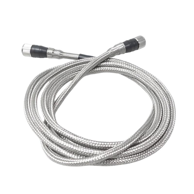
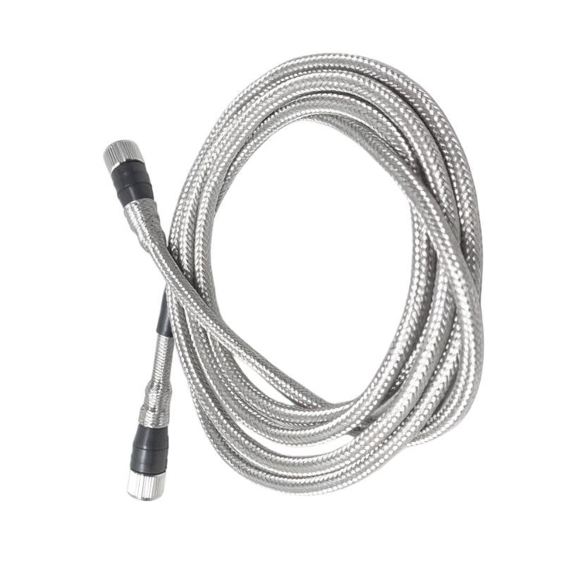
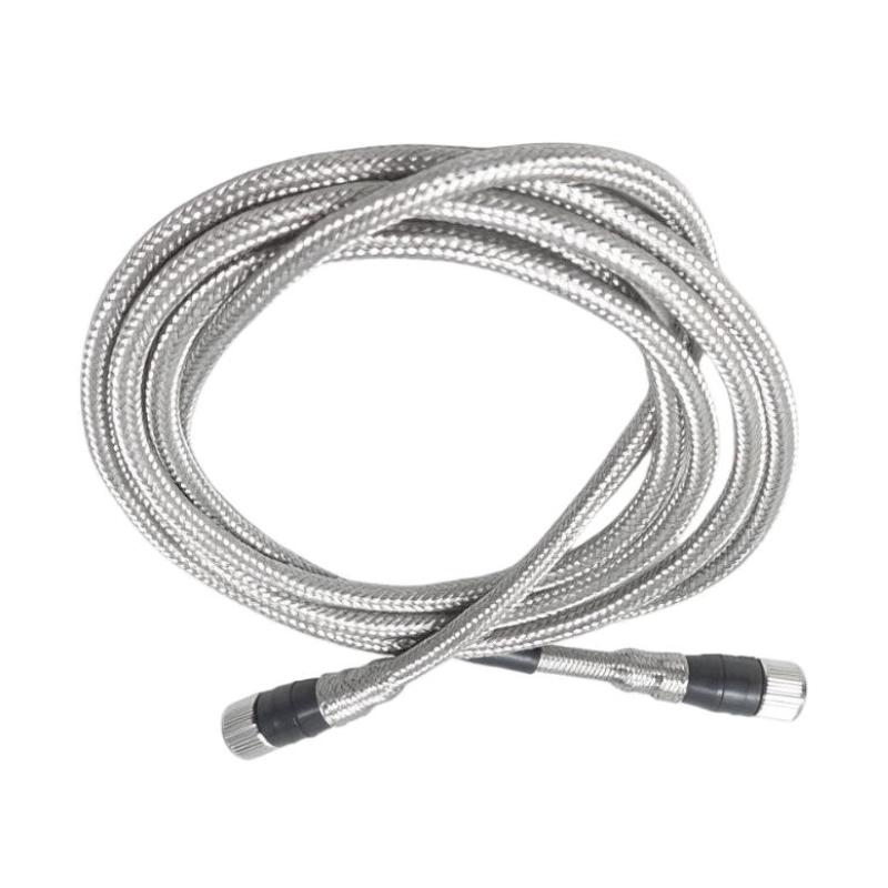
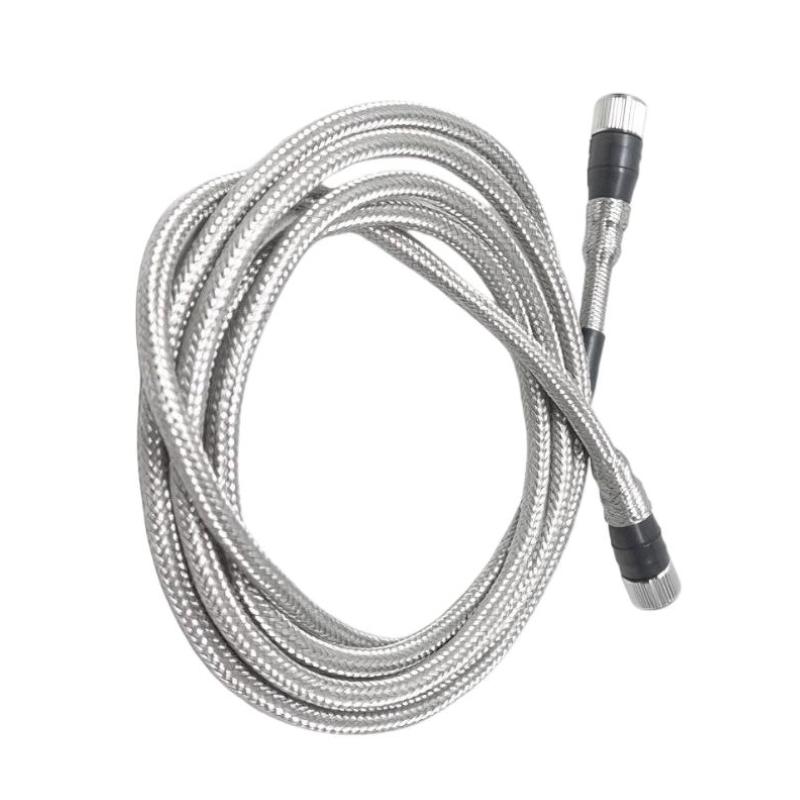
- Bently Nevada
- 200151-60-03-10
- Accelerometer Interface Standard Cable
- USA
- 6 meters
- 0.058 kg
- Xiamen, China
- New & In Stock
- T/T, PayPal, Western Union
- 1 Year
- 1-3 Working Days
- DHL, UPS, TNT, FedEx and EMS.
- 24-Hour Service
- COO
- 4
Our advantage

Global Logistics
We have a 10-year logistics and express cooperation agreement, so our products can be shipped to any place in the world.

Brand new and original
Our products are imported in bulk from the place of origin. Because of the cooperative relationship, our products are all original and 100% new.

24-hour service
We provide 7*24 hours service to our customers. We will be there whenever you need us.

Price advantage
All our products are priced very favorably because we have our own warehouse and supply.
| Company Information | |||
| [email protected] | |||
| Mobile | +8615980777398 | ||
| +8615980777398 | |||
| 15980777398 |
Product Overview
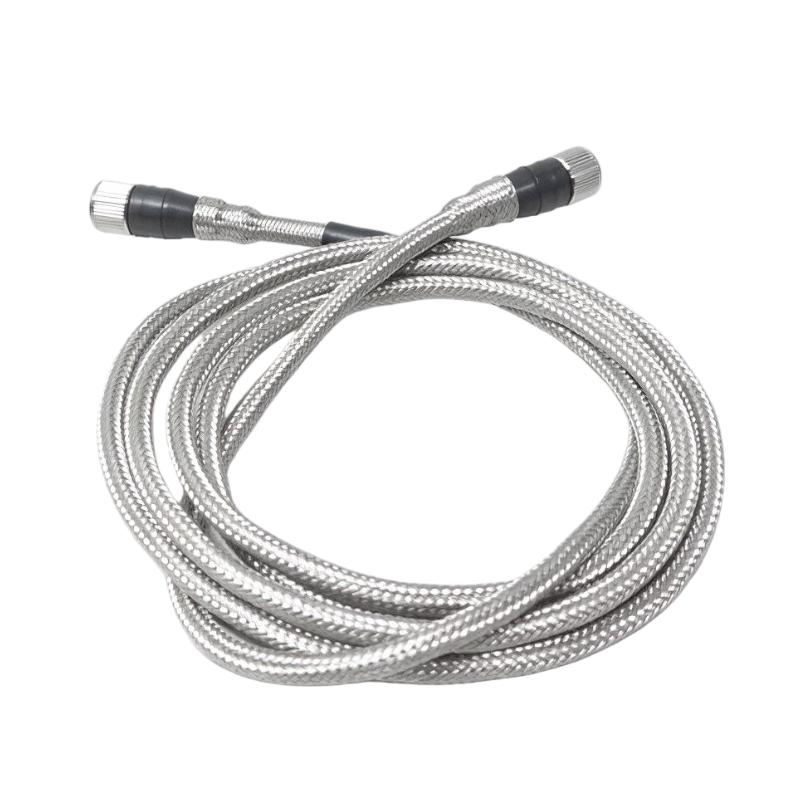
The Bently Nevada 200151-60-03-10 Accelerometer Interface Standard Cable is an industrial sensor connection cable designed for use with compatible Bently Nevada accelerometers and machinery vibration monitoring systems. It provides the electrical connection between an accelerometer and its associated monitoring equipment, allowing vibration signals to be transmitted for machinery condition assessment.
Accelerometers are widely used in industrial facilities to measure machine vibration. Their signals help maintenance personnel evaluate the operating condition of rotating equipment such as motors, pumps, compressors, fans, and turbines. A suitable connection cable is essential because poor connections, damaged conductors, or electrical interference can affect the quality and reliability of vibration measurements.
The 200151-60-03-10 is a 6-meter version of the 200151 Accelerometer Interface Standard Cable. Its configuration includes connectors at both ends, a blue cable with protective armor, and enhanced coupling nuts on both ends. These features make it suitable for installations where the sensor and monitoring connection point are separated by a moderate distance and where additional mechanical protection is desirable.
The cable is part of a broader Bently Nevada accelerometer accessory range. Its exact compatibility should be checked against the accelerometer model, connector arrangement, and monitoring-system wiring requirements before installation.
Technical Specifications
| Parameter | Specification |
|---|---|
| Brand | Bently Nevada |
| Manufacturer | Baker Hughes |
| Model | 200151-60-03-10 |
| Product Type | Accelerometer Interface Standard Cable |
| Cable Series | 200151 |
| Cable Length | 6.0 meters |
| Connector Configuration | Connectors on both ends |
| Armor Option | 03 – Blue cable with armor |
| Coupling Nut Option | 10 – Enhanced coupling nuts on both ends |
| Minimum Bend Radius | 63.5 mm |
| Operating Temperature | -20°C to +100°C |
| Extended Temperature | -55°C to +121°C when non-flexing, subject to manufacturer conditions |
| Cable Construction | 4-conductor, 22 AWG, braided shield and drain wire |
| Shield Coverage | At least 85% |
| Connector Seal | IP67 when properly mated |
| Dimensions | Cable assembly; overall dimensions depend on packaging and coiling |
| Weight Provided | 0.058 kg |
| Typical Application | Accelerometer signal transmission and machinery vibration monitoring |
Note: The weight is the supplied listing value and has not been independently confirmed against a manufacturer weight specification. Verify the actual cable assembly and packaging weight before shipping.
Function and Working Principle
The primary function of the 200151-60-03-10 is to provide a reliable electrical connection between a compatible accelerometer and the associated monitoring equipment.
1. Accelerometer Signal Transmission
An accelerometer detects mechanical vibration and converts it into an electrical signal. The signal is transmitted through the cable to a monitoring device, where it can be processed and evaluated.
The 200151 cable provides the connection required for this signal path. Correct cable selection helps maintain the intended electrical connection between the sensor and the monitoring system.
2. Shielded Cable Construction
Industrial facilities often contain electrical motors, variable frequency drives, switching equipment, and power cables that can generate electromagnetic interference.
The 200151 cable uses a shielded construction with a drain wire. The shield helps reduce the influence of external electrical noise when correctly grounded and installed according to the system requirements.
Proper cable routing remains important. Sensor cables should be kept away from high-power conductors where practical, and grounding arrangements should follow the applicable manufacturer’s instructions.
3. Armored Cable Protection
The model suffix 03 identifies the blue cable with protective armor. The armor provides an additional mechanical protection layer for installations where cables may be exposed to physical contact or other mechanical hazards.
This feature is particularly relevant in industrial environments containing moving equipment, cable trays, machinery frames, and maintenance access areas.
Armoring does not eliminate the need for proper cable routing, support, and protection against excessive tension or sharp edges.
4. Enhanced Coupling Nuts
The final suffix 10 identifies the enhanced coupling nut option. This option provides improved grip when tightening the cable connections and is fitted at both ends of the 200151 cable assembly.
Secure connector engagement helps maintain a stable connection during normal equipment operation. Installation personnel should tighten the connectors using the recommended procedure rather than applying excessive force.
5. Environmental Sealing
The cable’s molded connectors provide an IP67 seal when properly connected to compatible transducers and mating hardware. This helps protect the connection against dust and temporary water immersion under the specified test conditions.
The sealing performance depends on correct mating, connector condition, and the use of compatible components. Damaged seals or improperly tightened connectors can compromise environmental protection.
Role in Industrial Machinery Monitoring Systems
The 200151-60-03-10 is a connection component in a machinery condition monitoring arrangement. It does not measure vibration independently. Instead, it connects a compatible accelerometer to the equipment that receives and processes the sensor signal.
Accelerometer Connection
The cable connects the sensor to the corresponding monitoring interface. Its 6-meter length provides installation flexibility where the sensor location and connection point are separated by a moderate distance.
Before installation, confirm the sensor connector type and cable compatibility. A cable that appears physically similar may have a different connector arrangement or coupling option.
Monitoring Equipment Integration
After the accelerometer signal reaches the monitoring equipment, the system can process vibration data and provide information for machinery condition assessment.
Depending on the monitoring architecture, this information may be used for vibration trending, alarm evaluation, maintenance planning, and equipment protection.
The cable itself does not perform signal analysis, alarm generation, or machinery shutdown. These functions are handled by the connected monitoring and control equipment.
Condition-Based Maintenance
Reliable sensor connections are important for condition-based maintenance programs. A stable signal path helps maintenance personnel distinguish genuine machinery vibration changes from problems caused by loose or damaged connections.
Periodic inspection of the cable and connectors can therefore support the reliability of the wider monitoring installation.
Industrial Applications
The Bently Nevada 200151-60-03-10 can be used in compatible accelerometer installations across industrial facilities.
1. Electric Motors
Electric motors are widely used in manufacturing plants, power stations, and process industries. Accelerometers can monitor vibration associated with bearing wear, mechanical looseness, imbalance, and other developing problems.
The cable provides the electrical connection between a compatible accelerometer and the monitoring equipment.
2. Pumps and Pumping Systems
Centrifugal pumps and other rotating pumps may experience vibration changes caused by bearing deterioration, alignment problems, cavitation, or hydraulic operating conditions.
A properly installed accelerometer and cable assembly can support continuous vibration monitoring of suitable pump equipment.
3. Industrial Compressors
Compressors are important in petrochemical plants, gas processing facilities, refrigeration systems, and manufacturing operations.
Vibration monitoring can help maintenance teams evaluate the condition of compressor components and identify abnormal operating trends. The cable provides the connection needed to transmit the accelerometer signal.
4. Fans and Blowers
Industrial fans and blowers operate in ventilation, combustion-air, cooling, and process-gas systems. Vibration monitoring can help identify imbalance, bearing problems, and mechanical looseness.
The armored cable configuration can be useful where sensor wiring needs additional mechanical protection.
5. Turbines and Power Generation Equipment
Power generation facilities use vibration monitoring to assess the condition of rotating machinery. Accelerometers may be installed at selected measurement locations according to the monitoring strategy.
The 200151 cable can support compatible accelerometer connections where its length, connector type, and installation characteristics meet the system requirements.
6. Industrial Production Machinery
Manufacturing equipment may contain motors, gearboxes, pumps, and other rotating components. Accelerometer-based monitoring can provide useful information for maintenance teams responsible for equipment availability and reliability.
Installation and System Integration
Correct installation helps maintain signal quality and protect the cable assembly from premature damage.
1. Verify Cable Compatibility
Before installation, confirm that the cable is suitable for the intended Bently Nevada accelerometer and monitoring arrangement.
The 200151-60-03-10 has connectors at both ends. Its enhanced coupling nuts are provided at both ends as indicated by the 10 suffix.
Do not assume that every Bently Nevada accelerometer cable is interchangeable. Check the sensor connector, mating interface, and system documentation.
2. Plan the Cable Route
The cable length is 6 meters. Plan the route to provide sufficient length for connection and maintenance access without leaving unnecessary cable loops near moving machinery.
Avoid routing the cable across sharp edges, hot surfaces, moving components, or locations where it may be crushed. Use suitable cable supports and protective routing where necessary.
3. Observe the Minimum Bend Radius
The documented minimum bend radius for the 200151 cable is 63.5 mm.
Avoid tight bends, kinks, or repeated sharp flexing. Bending the cable below its specified radius can damage its internal conductors, shielding, or protective construction.
The cable should also be handled carefully at connector entry points because excessive bending near the connector can place unnecessary mechanical stress on the assembly.
4. Connect and Secure the Coupling Nuts
Inspect both connectors before installation. Check for contamination, damaged threads, worn sealing surfaces, or other visible defects.
Align each connector correctly before tightening. Use the enhanced coupling nuts to obtain secure engagement, following the manufacturer’s recommended installation procedure.
Do not use excessive force, as this may damage the connector or mating hardware.
5. Manage Electromagnetic Interference
Where practical, route accelerometer cables separately from high-voltage and high-current power conductors. Avoid unnecessary parallel routing with variable frequency drive output cables and other potential interference sources.
Follow the monitoring-system grounding and shielding instructions. Incorrect shield termination may reduce the effectiveness of the cable’s noise protection.
6. Inspect the Installation
After installation, check that the cable is supported, connectors are properly engaged, and no section is exposed to excessive mechanical stress.
Confirm that the monitoring equipment receives a stable sensor signal. If the signal is abnormal, inspect the sensor, cable, connectors, and monitoring input before concluding that the accelerometer itself is defective.
Compatible System Components
The 200151-60-03-10 is an accessory cable and must be used with compatible sensors and monitoring equipment.
| Component | Function | Compatibility Considerations |
|---|---|---|
| Bently Nevada accelerometer | Detects mechanical vibration | Verify the sensor model and connector type |
| Accelerometer interface | Provides the sensor connection to the monitoring arrangement | Confirm the correct input and connection configuration |
| Machinery monitoring system | Receives and processes vibration signals | Verify supported sensor type and electrical requirements |
| Vibration monitoring module | Processes measurement signals | Check input specifications and system configuration |
| PLC or DCS | Uses monitoring information in plant control or supervisory logic | Integration depends on the monitoring system’s available outputs and communication interfaces |
| Cable tray or conduit | Supports and protects cable routing | Select a route that avoids mechanical damage and electrical interference |
| Connector mating hardware | Provides the physical and electrical connection | Confirm compatible threads, sealing surfaces, and coupling arrangement |
These components are examples of a complete monitoring installation. They are not necessarily included with the cable.
Alternative Models and Replacement Considerations
The 200151 family includes different cable lengths, armor options, and coupling nut configurations. Selection should be based on the exact installation requirements.
| Model or Configuration | Main Difference |
|---|---|
| 200151-20-03-10 | 2-meter cable, armored, enhanced coupling nuts |
| 200151-40-03-10 | 4-meter cable, armored, enhanced coupling nuts |
| 200151-60-03-00 | 6-meter cable, armored, standard coupling nuts |
| 200151-60-03-02 | 6-meter cable, armored, nylon coupling nuts |
| 200151-60-02-00 | 6-meter cable without armor, standard coupling nuts |
| 200152 cable series | Different connection arrangement, with connector on the accelerometer end only |
Before selecting an alternative, compare the following:
- Cable length and routing requirements.
- Connector configuration at each end.
- Armor or non-armor construction.
- Coupling nut type.
- Accelerometer compatibility.
- Minimum bend radius.
- Operating temperature range.
- Environmental sealing requirements.
- Shielding and grounding arrangement.
A cable with the same length may still be unsuitable if its connector arrangement or coupling nut configuration differs.
Key Advantages
6-Meter Connection Length
The 6-meter cable provides flexibility for installations where the accelerometer and monitoring connection point are separated by a moderate distance.
Armored Construction
The blue armored cable configuration offers additional mechanical protection compared with an unarmored cable option.
Enhanced Coupling Nuts
The enhanced coupling nuts at both ends provide improved grip during connector tightening and help simplify secure installation.
Shielded Signal Path
The four-conductor shielded construction supports the transmission of accelerometer signals in industrial environments where electrical interference may be present.
Molded Connector Design
The molded connectors provide a defined connection arrangement and an IP67 seal when properly mated with compatible hardware.
Industrial Monitoring Applications
The cable supports compatible accelerometer installations used for monitoring motors, pumps, compressors, fans, and other rotating machinery.
Technical FAQs
1. What is the Bently Nevada 200151-60-03-10?
It is an Accelerometer Interface Standard Cable designed to connect compatible Bently Nevada accelerometers with associated monitoring equipment.
2. What is the cable length?
The cable is 6.0 meters long. The 60 section of the part number identifies the 6-meter length option.
3. What does the 03 suffix mean?
The 03 suffix identifies the blue cable with protective armor.
4. What does the 10 suffix mean?
The 10 suffix identifies the enhanced coupling nut option. For the 200151 cable, this option provides enhanced coupling nuts at both ends.
5. Does the cable have connectors at both ends?
Yes. The 200151 series is specified as an Accelerometer Interface Standard Cable with connectors on both ends.
6. What is the minimum bend radius?
The documented minimum bend radius is 63.5 mm. Avoid tighter bends to protect the cable’s internal construction.
7. What is its operating temperature range?
The specified operating temperature range is -20°C to +100°C. Lower temperatures may be permitted when the cable remains stationary and is not flexed, subject to the manufacturer’s conditions.
8. Is the cable waterproof?
The molded connectors provide an IP67 seal when properly connected to compatible transducers and mating hardware. This does not mean the complete installation can be exposed to every form of water or environmental condition.
9. Can it be used with any Bently Nevada accelerometer?
No. The cable must match the accelerometer’s connector and the monitoring system’s requirements. Verify the exact sensor model before ordering.
10. What should be checked when replacing an existing cable?
Check the complete part number, cable length, armor option, coupling nut type, connector condition, and sensor compatibility. Also inspect the cable route for sharp bends, crushing, heat exposure, and other possible causes of damage.
Procurement and Maintenance Recommendations
When purchasing the Bently Nevada 200151-60-03-10, verify the complete part number rather than ordering solely by the description “accelerometer cable.” The length, armor, and coupling nut options are encoded in the catalog number and determine the actual configuration.
For replacement projects, compare the existing cable’s connectors and coupling nuts with the proposed replacement. Confirm that the 6-meter length is adequate for the installed route and that the armored construction is suitable for the operating environment.
For new or surplus equipment, request clear photographs of both connectors and the cable jacket. Check for cuts, crushing, exposed armor, damaged threads, contamination, or signs of previous improper installation. Confirm whether the supplied weight refers to the cable itself or the packaged shipment.
During routine maintenance, inspect the cable route, support points, connectors, and sealing surfaces. Replace assemblies that show visible damage or produce intermittent signal problems after the sensor and monitoring input have been checked.
Conclusion
The Bently Nevada 200151-60-03-10 Accelerometer Interface Standard Cable is a 6-meter armored cable designed for compatible accelerometer-based machinery vibration monitoring systems. Its configuration includes connectors on both ends, a blue armored cable, and enhanced coupling nuts at both ends.
With its shielded construction, defined bend-radius requirements, and molded connector design, it provides an important connection component in industrial condition monitoring installations. Correct cable identification, connector compatibility, routing, and installation are essential for maintaining reliable vibration signal transmission.