
NewsNEWCENTER
Featured products
Contact Us
Allen Bradley MPL-A560E-M-X189 Servo Motor Installation Guide
2026-10-12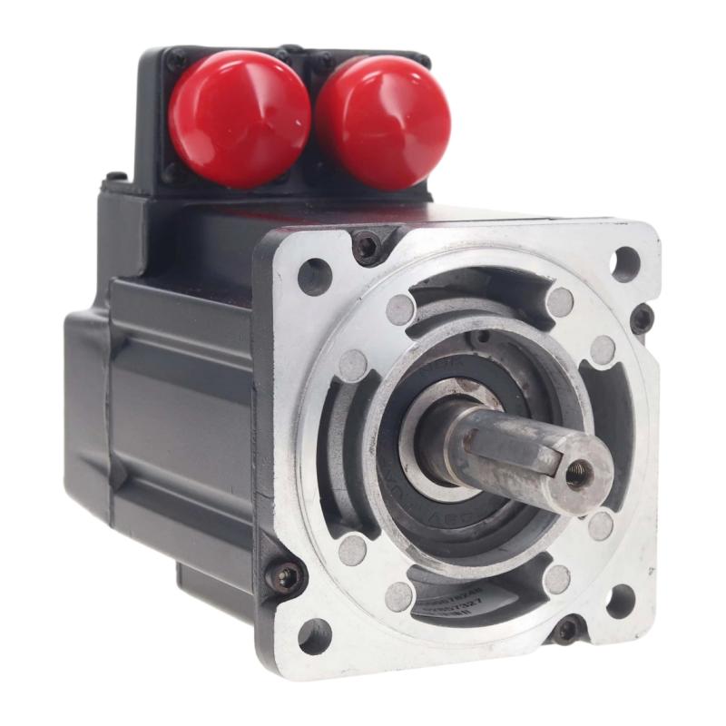
The Allen Bradley MPL-A560E-M-X189 Servo Motor installation process involves mechanical mounting, shaft alignment, motor power wiring, feedback integration, compatible servo drive configuration, and controlled commissioning. Designed for industrial motion-control applications, the motor must be correctly matched to the machine’s mechanical requirements and the installed drive system. Careful installation helps reduce positioning errors, unexpected drive faults, excessive vibration, and premature mechanical wear.
Allen Bradley MPL-A560E-M-X189 Servo Motor Overview
The Allen Bradley MPL-A560E-M-X189 is identified by its catalog number as an MPL-series servo motor. In a servo-controlled machine, the motor converts electrical energy into controlled mechanical motion. The servo drive regulates motor operation, while feedback allows the control system to monitor and adjust movement according to the application requirements.
A typical servo axis operates through the following arrangement:
PLC / Motion Controller
          ↓
      Servo Drive
          ↓
MPL-A560E-M-X189 Servo Motor
          ↓
 Coupling / Gearbox / Machine Load

Motor Feedback ─────→ Servo Drive
Drive Status ────────→ Controller
Before installation, verify the complete motor catalog number, nameplate ratings, connector configuration, feedback interface, and compatibility with the selected drive. Do not assume that motors with similar catalog numbers share identical electrical characteristics or mounting requirements.
Installation Preparation and Safety Requirements
Before installing the MPL-A560E-M-X189, review the machine design, drive documentation, and applicable maintenance procedures. Servo motors can generate unexpected movement, and their associated drive circuits may retain hazardous electrical energy after power is removed.
- Confirm the motor’s complete catalog number and nameplate details.
- Verify compatibility with the intended servo drive.
- Inspect the housing, shaft, mounting flange, and connectors.
- Check the mechanical load, coupling, and mounting arrangement.
- Prepare the specified motor power and feedback cables.
- Confirm protective grounding and cable-shielding requirements.
- Verify that the machine can be safely isolated during installation.
- Ensure travel limits and safety interlocks are available for commissioning.
- Record the existing wiring and drive configuration where replacing a motor.
MPL-A560E-M-X189 Mechanical Mounting
Mount the Allen Bradley MPL-A560E-M-X189 on a rigid, properly prepared mounting surface. The mounting face should be clean and free from debris, and the motor should sit evenly against the machine structure. Incorrect mounting can introduce vibration, misalignment, and additional stress on the motor bearings.
Shaft Alignment and Coupling
Check the coupling and driven shaft before securing the motor. Angular or parallel misalignment can increase bearing loads and reduce positioning accuracy. Use the alignment procedure specified for the machine and coupling assembly.
- Verify shaft and coupling compatibility.
- Check alignment before tightening the mounting hardware.
- Confirm that the driven mechanism moves freely where appropriate.
- Avoid applying excessive radial or axial force to the motor shaft.
- Secure mounting hardware according to the specified torque.
- Inspect the assembly for mechanical interference.
Allen Bradley MPL-A560E-M-X189 Wiring Guide
Correct wiring is essential for reliable servo operation. The motor’s power and feedback connections must match the compatible drive and the exact hardware configuration. Refer to the applicable documentation for terminal assignments, connector pinouts, cable specifications, and grounding requirements.
Motor Power Wiring
Use the approved motor power cable and compatible connectors. Before energizing the drive, inspect the cable for damage, confirm the connection arrangement, and verify protective grounding. Incorrect power wiring can cause drive faults or damage to the motor and drive.
Feedback Cable Installation
The servo drive relies on motor feedback to regulate movement. An incompatible or incorrectly connected feedback cable may prevent the drive from recognizing the motor or may produce feedback-related faults.
- Confirm feedback compatibility with the selected drive.
- Inspect connectors for contamination or damaged contacts.
- Ensure connectors are fully seated and secured.
- Route feedback wiring away from major electrical interference sources.
- Follow the specified cable shielding and grounding arrangement.
MPL-A560E-M-X189 Servo Drive Setup
Once the motor is mechanically installed and wired, configure the servo drive and motion controller. The motor identification and feedback settings must match the installed hardware. Avoid copying parameters from another servo motor unless compatibility has been confirmed.
- Verify the motor and drive catalog numbers.
- Confirm the motor feedback connection.
- Select the appropriate motor configuration in the engineering software.
- Configure axis scaling and motion limits.
- Review acceleration, deceleration, and speed limits.
- Confirm the motor direction and machine coordinate system.
- Verify drive enable conditions and safety interlocks.
- Review fault handling before enabling movement.
Allen Bradley MPL-A560E-M-X189 Commissioning Procedure
Commissioning should progress from static inspection to controlled movement. Do not proceed to a full-speed test until the electrical connections, configuration, and mechanical installation have been verified.
Mechanical Inspection
        ↓
Power and Feedback Wiring Check
        ↓
Drive Configuration
        ↓
Drive Status Verification
        ↓
Controlled Servo Enable
        ↓
Direction Test
        ↓
Low-Speed Movement Test
        ↓
Position Feedback Verification
        ↓
Application-Level Commissioning
Initial Power-Up and Drive Diagnostics
Before enabling the axis, check the drive’s ready status and diagnostic information. Resolve any motor identification, feedback, power, or configuration fault before continuing.
Direction and Low-Speed Movement
Use an approved commissioning mode to confirm that the motor rotates in the intended direction. Keep the initial movement slow and limited, and verify that the machine’s travel limits and safety functions operate correctly.
Motion Performance Verification
After confirming basic movement, test the required motion profile under controlled conditions. Monitor vibration, noise, following error, positioning behavior, and drive diagnostics. Increase speed and acceleration gradually within the machine’s approved operating limits.
Common MPL-A560E-M-X189 Installation Mistakes
- Using an incompatible servo drive.
- Connecting feedback cables without verifying compatibility.
- Assuming terminal assignments from another motor model.
- Ignoring shaft alignment and coupling condition.
- Routing feedback cables alongside high-interference conductors.
- Using unverified drive parameters.
- Enabling the axis before checking travel limits and safety interlocks.
- Failing to record the original configuration during replacement.
Representative Servo Motor Commissioning Case
Consider a representative machine installation in which a newly installed servo motor triggers a feedback fault during startup. The technician verifies that the motor is securely mounted and that the power connections are correct. A subsequent inspection identifies an incompatible feedback cable carried over from the previous installation.
After the correct cable is installed and the drive configuration is checked, the feedback fault clears. The technician then performs a controlled low-speed movement test before validating the full motion sequence.
This illustrative example demonstrates why motor compatibility and feedback verification should be part of the initial commissioning checklist.
Allen Bradley MPL-A560E-M-X189 Installation FAQs
What is the MPL-A560E-M-X189 Servo Motor used for?
It is an industrial servo motor intended for integration into a compatible motion-control system for controlled mechanical movement. The exact application depends on its verified ratings and the machine design.
How do I select a compatible servo drive?
Compare the motor’s catalog number, nameplate ratings, feedback interface, connector configuration, and electrical requirements with the drive’s supported motor specifications.
Why must feedback wiring be checked before commissioning?
The drive requires valid feedback to regulate motor operation. An incompatible or incorrectly connected feedback circuit can prevent startup or cause motion faults.
What should be verified before the first movement?
Check mechanical mounting, shaft alignment, power wiring, feedback connections, drive configuration, travel limits, safety interlocks, and the machine’s safe operating condition.
Technical Summary
Successful installation of the Allen Bradley MPL-A560E-M-X189 Servo Motor depends on verified drive compatibility, correct mechanical alignment, reliable power and feedback wiring, and a structured commissioning procedure. Confirming the hardware details before energizing the system helps reduce startup errors and supports dependable operation in industrial motion-control applications.