

ProductPRODUCT
Featured products
Contact Us
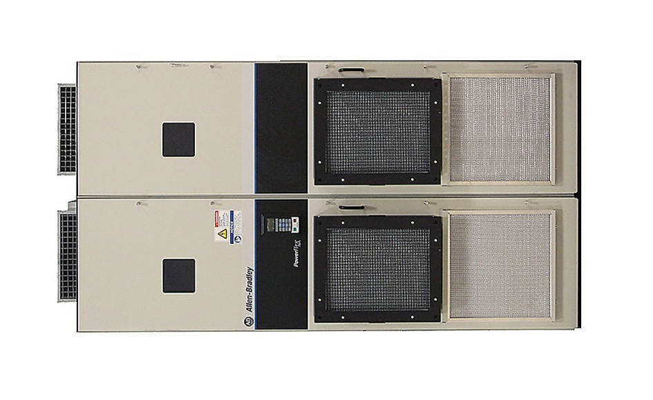
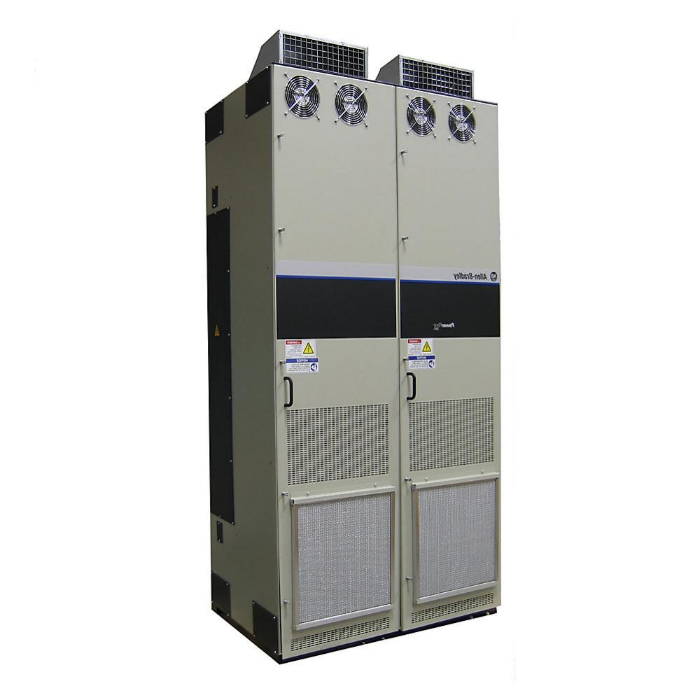
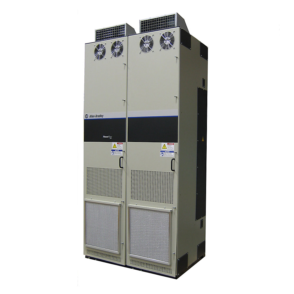
- Allen Bradley
- 20G1G3C367LNANNNNN
- PowerFlex AC Drive
- USA
- 2102 × 606 × 600 mm
- 861kg
- Xiamen, China
- New & In Stock
- T/T, PayPal, Western Union
- 1 Year
- 1-3 Working Days
- DHL, UPS, TNT, FedEx and EMS.
- 24-Hour Service
- COO
- 1
Our advantage

Global Logistics
We have a 10-year logistics and express cooperation agreement, so our products can be shipped to any place in the world.

Brand new and original
Our products are imported in bulk from the place of origin. Because of the cooperative relationship, our products are all original and 100% new.

24-hour service
We provide 7*24 hours service to our customers. We will be there whenever you need us.

Price advantage
All our products are priced very favorably because we have our own warehouse and supply.
| Company Information | |||
| [email protected] | |||
| Mobile | +8615980777398 | ||
| +8615980777398 | |||
| 15980777398 |
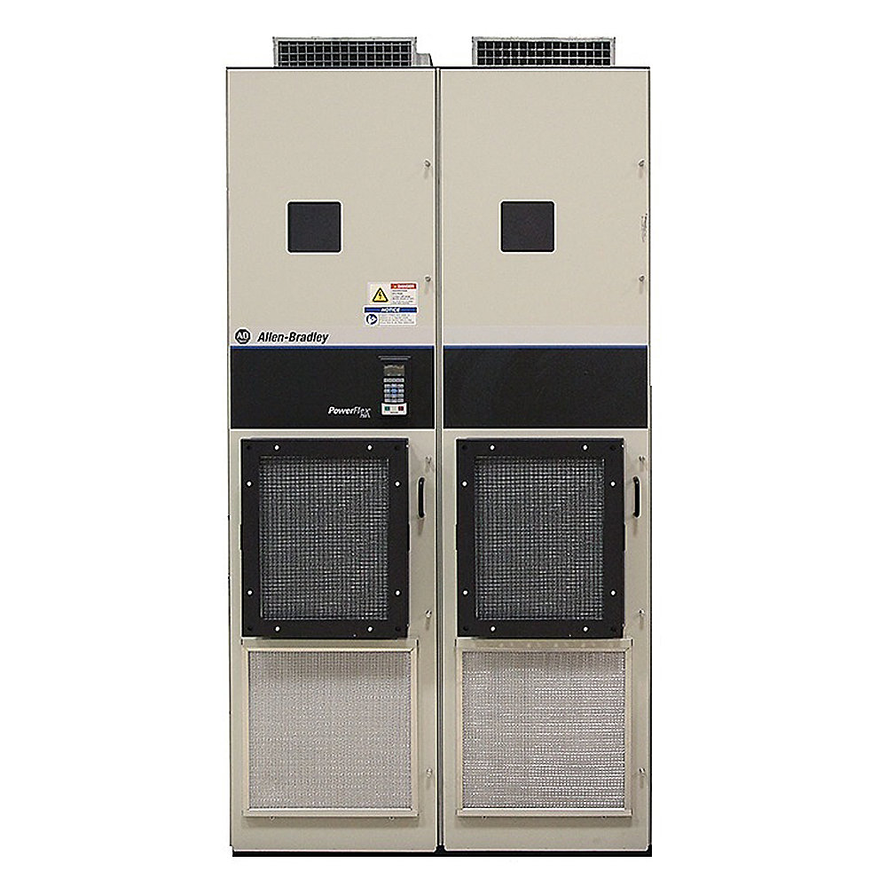
Allen-Bradley 20G1G3C367LNANNNNN PowerFlex 755 AC Drive
1. Product Overview
The Allen-Bradley 20G1G3C367LNANNNNN is a high-power PowerFlex 755 AC variable frequency drive designed for demanding industrial motor-control applications.
It is a 400 VAC, three-phase drive with a nominal output current rating of 367 A. The unit uses an air-cooled construction, a floor-mounted installation arrangement, and a Type 1 / IP21 enclosure configuration.
The drive belongs to the PowerFlex 755 family and uses an Active Front End (AFE) input architecture intended to provide low-harmonic operation and improved control of input power quality.
With a large Frame 8B construction, the 20G1G3C367LNANNNNN is intended for applications where considerably more motor power and current capacity are required than can normally be provided by compact wall-mounted drives.
The model is particularly suitable for large motors used in conveyors, pumps, fans, process machinery, material-handling systems, production lines, and other continuously operating industrial equipment.
The nominal drive current is 367 A, while the associated DC nominal current is approximately 381 A. Its 400 VAC three-phase electrical configuration makes it suitable for industrial power systems based on the 380–400 VAC class.
The standard configuration is air cooled, which provides a practical method of removing heat generated by the power semiconductor section during continuous operation.
The enclosure is rated Type 1 / IP21, making the drive appropriate for controlled indoor industrial environments where protection from ordinary accidental contact and limited environmental exposure is required.
The drive is floor mounted rather than designed as a small cabinet-mounted or compact wall-mounted unit. This is consistent with its high-power rating and large frame construction.
The published physical dimensions are approximately 1200 mm high, 400 mm long, and 600 mm wide, with an approximate product weight of 150 kg. When represented in a conventional H × W × D arrangement, this corresponds to approximately 1200 × 600 × 400 mm, subject to the dimensional convention used for the particular enclosure documentation.
The model is therefore best regarded as a large industrial drive rather than a general-purpose compact inverter.
2. Basic Product Parameters
| Parameter | Specification |
|---|---|
| Brand | Allen-Bradley |
| Product Family | PowerFlex 755 |
| Model | 20G1G3C367LNANNNNN |
| Drive Type | AC variable frequency drive |
| Input Voltage | 400 VAC |
| Input Phase | Three-phase |
| Nominal Drive Current | 367 A |
| Nominal DC Current | Approximately 381 A |
| Cooling Method | Air cooled |
| Input Technology | Active Front End (AFE), low-harmonic configuration |
| Enclosure | Type 1 / IP21 |
| Mounting | Floor mount |
| Frame Size | 8B |
| Harmonic Performance | Low-harmonic AFE architecture |
| EMC / Filtering | Configuration does not include the optional EMC filter in this catalog configuration |
| Installation Environment | Controlled industrial / indoor environment |
| Application Type | Industrial motor control and automation |
| Product Category | High-power AC drive |
| Approximate Height | 1200 mm |
| Approximate Width | 600 mm |
| Approximate Depth | 400 mm |
| Dimensions | Approx. 1200 × 600 × 400 mm, H × W × D |
| Approximate Weight | 150 kg |
| Mounting Requirement | Floor-standing installation |
| Motor Control Application | Variable-speed motor operation |
| Typical Motor Loads | Pumps, fans, conveyors, process machinery, material handling |
| Intended Power Level | High-power industrial applications |
The electrical configuration of the 20G1G3C367LNANNNNN is centered around a 400 VAC three-phase supply and a 367 A nominal current rating. This gives the drive a substantial current-handling capability for large industrial motors.
The physical size and 150 kg approximate weight should be considered during cabinet layout, transportation, lifting, installation, and maintenance planning.
The AFE configuration is particularly relevant when the installation has strict requirements concerning input current quality, harmonic performance, regenerative operation, or the interaction between large variable-speed drives and the plant electrical distribution system.
3. Product Identification
Model: 20G1G3C367LNANNNNN
Brand: Allen-Bradley
Series: PowerFlex 755
Product Type: High-power AC variable frequency drive
Input: 400 VAC, three-phase
Nominal Current: 367 A
Frame: 8B
Cooling: Air cooled
Enclosure: Type 1 / IP21
Mounting: Floor mounted
Input Architecture: Active Front End, low-harmonic configuration
The long catalog number identifies a specific combination of voltage class, current rating, frame size, enclosure arrangement, input configuration, and other factory-defined options.
For industrial procurement, the complete catalog number should be used rather than selecting a drive only by the PowerFlex family name.
4. Product Introduction
The PowerFlex 755 family is designed for advanced variable-speed control of industrial motors.
Unlike small general-purpose frequency converters that are commonly installed directly beside individual machines, a high-power Frame 8 drive such as the 20G1G3C367LNANNNNN is intended for larger industrial equipment and centralized motor-control installations.
The drive controls motor speed and torque by regulating the electrical power supplied to the motor. This allows machinery to operate at different speeds according to process requirements rather than simply running at fixed line frequency.
Variable-speed control can be particularly valuable in applications where motor speed needs to change according to production demand.
For example, a pump does not always need to operate at maximum speed. A fan may need to follow changing airflow requirements. A conveyor may require different speeds during different production stages. A process motor may need controlled acceleration, controlled deceleration, or accurate torque regulation.
The use of a high-capacity drive allows these requirements to be managed electronically.
The 20G1G3C367LNANNNNN also belongs to a class of drives designed for applications where electrical power quality is an important consideration.
Its AFE input architecture is intended to provide low-harmonic operation and more controlled interaction with the incoming electrical supply than a conventional uncontrolled rectifier arrangement.
This becomes increasingly important as the installed motor-drive population increases and the electrical system contains a large number of nonlinear loads.
5. Active Front End and Low-Harmonic Operation
One of the important characteristics of the 20G1G3C367LNANNNNN is its Active Front End configuration.
A conventional AC drive normally converts incoming AC power into DC power through a rectifier stage. Depending on the design, this can introduce harmonic currents into the incoming electrical system.
An AFE architecture uses controlled switching devices to provide greater control over the relationship between the drive and the incoming AC supply.
This can help reduce input current distortion and improve the overall power-quality characteristics of the installation.
For large industrial facilities, harmonic control can become increasingly important because multiple large drives operating simultaneously can have a noticeable effect on the electrical distribution network.
Low-harmonic operation can therefore be useful in facilities with sensitive electrical equipment, generators, transformers, large numbers of drives, or strict power-quality requirements.
The AFE approach can also support applications where regenerative energy handling is important, depending on the complete system configuration.
6. Electrical Characteristics
The 400 VAC three-phase input makes this model appropriate for industrial electrical systems operating in the 400 V class.
The 367 A nominal current rating places this drive in a high-capacity industrial category.
At this current level, installation design must consider more than simply connecting the drive to a motor. The incoming feeder, protective devices, disconnect equipment, grounding system, cable sizing, thermal management, cabinet arrangement, and motor-cable installation all need to be coordinated.
The 20G1G3C367LNANNNNN is therefore normally installed as part of a properly engineered industrial electrical system.
The drive’s current rating should also be matched to the actual motor operating conditions.
Motor selection should consider rated current, overload requirements, acceleration requirements, duty cycle, ambient conditions, motor efficiency, motor insulation, cable length, and the required speed range.
A drive should not be selected solely from the motor’s nominal horsepower or kilowatt value.
7. Mechanical Parameters
| Mechanical Parameter | Specification |
|---|---|
| Model | 20G1G3C367LNANNNNN |
| Frame Size | 8B |
| Mounting | Floor mount |
| Cooling | Air cooled |
| Enclosure | Type 1 / IP21 |
| Height | Approx. 1200 mm |
| Width | Approx. 600 mm |
| Depth | Approx. 400 mm |
| Overall Dimensions | Approx. 1200 × 600 × 400 mm |
| Weight | Approx. 150 kg |
| Installation Orientation | Upright / floor-standing |
| Installation Space | Adequate front and ventilation clearance required |
| Service Access | Required for power and control connections |
| Thermal Management | Forced-air / air-cooled arrangement |
Because the drive weighs approximately 150 kg, mechanical installation should be treated as a serious engineering requirement.
The mounting surface must be capable of supporting the drive and associated equipment without excessive vibration or deformation.
The installation area should also provide adequate clearance for ventilation and maintenance.
The airflow path must not be obstructed by adjacent equipment, cable trays, cabinet structures, dust accumulation, or other objects.
8. Main Product Advantages
8.1 High Current Capacity
The 367 A nominal current rating allows the drive to control substantially larger motors than compact variable-frequency drives.
This makes the model suitable for large pumps, fans, conveyors, process machines, compressors, material-handling equipment, and other high-power industrial loads.
8.2 Low-Harmonic AFE Architecture
The Active Front End is one of the major technical advantages of this configuration.
It is intended to provide improved control of input current and lower harmonic distortion compared with conventional drive input architectures.
This can be particularly valuable in large plants where several high-power drives operate simultaneously.
8.3 Industrial Floor-Mount Construction
The floor-mounted Frame 8B construction is appropriate for large installations.
Instead of forcing a large drive into a compact wall-mounted format, the mechanical design provides a practical structure for high-power electrical components and associated connections.
This approach can simplify integration into dedicated electrical rooms, drive cabinets, MCC areas, and large automation systems.
8.4 Air-Cooled Design
Air cooling provides a practical and established thermal-management method for high-power industrial drives.
The cooling system removes heat generated by the power electronics during operation.
Correct ventilation and environmental management are important to maintain reliable operation.
8.5 Type 1 / IP21 Enclosure
The Type 1 / IP21 configuration provides protection appropriate for controlled indoor industrial locations.
It is not intended to be treated as a waterproof outdoor enclosure.
Where the installation has high humidity, washdown requirements, conductive dust, corrosive chemicals, or outdoor exposure, the complete system design should provide the appropriate environmental protection.
8.6 Suitable for Continuous Industrial Operation
The PowerFlex 755 platform is intended for industrial motor-control applications where precise and repeatable motor operation is required.
The drive can be integrated into larger automation systems and used in applications where speed, torque, acceleration, deceleration, and process control need to be managed electronically.
9. Typical Applications
9.1 Conveyor Systems
The 20G1G3C367LNANNNNN can be used for large conveyor systems where motor speed needs to change according to production requirements.
Variable-speed operation can help control material flow, reduce mechanical shock during starting and stopping, and coordinate different conveyor sections.
For long conveyors, controlled acceleration can also help reduce mechanical stress on belts, couplings, gearboxes, and other components.
9.2 Pumping Systems
Large industrial pumps can require substantial motor power.
A variable-frequency drive can adjust pump speed according to process demand.
This is useful in water treatment, industrial water circulation, process cooling, chemical processing, manufacturing utilities, and other pumping applications.
When properly engineered, variable-speed operation can reduce unnecessary motor operation at full speed.
9.3 Industrial Fans
Large fans and blowers are another common application for high-power variable-speed drives.
The drive can regulate fan speed according to airflow demand.
This can improve process control and potentially reduce energy consumption compared with operating a motor continuously at full speed and controlling flow only through mechanical restrictions.
9.4 Material Handling
Large material-handling systems can benefit from controlled acceleration, controlled deceleration, and adjustable motor speed.
Examples include bulk-material systems, production conveyors, lifting-related auxiliary machinery, and industrial transfer systems.
The high current capacity of this model allows it to be used with larger motor systems.
9.5 Manufacturing Machinery
The drive can be applied to large production machines where motor speed and torque need to be controlled as part of an automated manufacturing process.
The exact suitability depends on motor characteristics, load profile, required control performance, and system architecture.
9.6 Process Industries
Large industrial processes often contain pumps, fans, conveyors, mixers, compressors, and other rotating equipment.
A high-power variable-frequency drive can provide centralized electronic control of these motor loads.
10. Advantages in Industrial Automation
The drive can become an important component within an automated production system.
Instead of operating a motor at a single fixed speed, the motor can be commanded to operate at different speeds according to process conditions.
This creates a closer relationship between motor operation and production requirements.
For automated equipment, controlled acceleration can also reduce sudden mechanical movement.
Controlled deceleration can reduce unnecessary mechanical shock during stopping.
Variable-speed operation can make it easier to synchronize different sections of a production line.
For example, a conveyor can be accelerated gradually, operated at a process-specific speed, and then decelerated according to the production sequence.
11. Advantages for Energy Management
A variable-speed drive can provide energy-management benefits in applications where the required motor output changes significantly over time.
This is particularly relevant to centrifugal pumps and fans.
If the process does not require full motor speed, reducing motor speed can reduce the power required by the system.
However, the actual energy savings depend on the machine’s load profile, mechanical system characteristics, operating schedule, motor efficiency, and control strategy.
Therefore, the drive should be considered an enabling technology for energy optimization rather than assuming a fixed percentage of energy savings for every installation.
12. Installation Considerations
Because the 20G1G3C367LNANNNNN is a high-power 367 A drive, installation requires careful planning.
The incoming electrical supply must be compatible with the drive’s voltage and phase requirements.
The feeder and protective equipment must be correctly selected for the installation.
Motor cables must be appropriately sized and routed.
Grounding and bonding should follow the requirements of the applicable electrical standards and the complete drive system.
The installation must also provide sufficient airflow.
The approximate 150 kg weight means that lifting and positioning should be planned before installation.
The physical dimensions of approximately 1200 × 600 × 400 mm should also be considered when designing the electrical room, cabinet arrangement, access route, and service area.
13. Maintenance Considerations
Air-cooled high-power drives require attention to their cooling system.
Dust accumulation can restrict airflow and reduce heat-transfer performance.
Cooling fans and ventilation passages should therefore be inspected as part of a preventive-maintenance program.
Electrical connections should also be inspected according to the maintenance requirements of the installation.
The surrounding environment should be monitored for excessive dust, moisture, corrosive substances, vibration, and abnormal temperature.
Because the drive is a high-energy electrical device, maintenance should be carried out by appropriately qualified personnel using the applicable safety procedures.
14. Five Related Models in the Same PowerFlex 755 Series
The following models are closely related PowerFlex 755 configurations. They use the same general high-power 400 V-class PowerFlex 755 platform, while the current and power ratings differ.
| Model | Series | Approx. Current Class | Typical 400 V Power Class | Frame | Cooling / Mounting | Dimensions | Weight |
|---|---|---|---|---|---|---|---|
| 20G1G3C302LNANNNNN | PowerFlex 755 | 302 A | Approx. 160 kW normal-duty class | 8 | Air cooled / floor mount | Configuration dependent; large Frame 8 enclosure | Configuration dependent |
| 20G1G3C460LNANNNNN | PowerFlex 755 | 460 A | Approx. 250 kW normal-duty class | 8 | Air cooled / floor mount | Configuration dependent; large Frame 8 enclosure | Configuration dependent |
| 20G1G3C540LNANNNNN | PowerFlex 755 | 540 A | Approx. 315 kW normal-duty class | 8 | Air cooled / floor mount | Configuration dependent; large Frame 8 enclosure | Configuration dependent |
| 20G1G3C585LNANNNNN | PowerFlex 755 | 585 A | Approx. 315 kW class | 8 | Air cooled / floor mount | Configuration dependent; large Frame 8 enclosure | Configuration dependent |
| 20G1G3C650LNANNNNN | PowerFlex 755 | 650 A | Approx. 355 kW normal-duty class | 8 | Air cooled / floor mount | Configuration dependent; large Frame 8 enclosure | Configuration dependent |
These models are useful when comparing the 20G1G3C367LNANNNNN with higher- or lower-current versions of the same general drive family.
The 302 A version is useful where the motor requirement is below the 367 A class.
The 460 A version provides additional current capacity when the 367 A rating is insufficient.
The 540 A, 585 A, and 650 A versions extend the same high-power concept into progressively larger motor applications.
The complete catalog suffix should always be checked before ordering because enclosure, input arrangement, filtering, braking, control, and other options can change the final configuration.
15. Same-Series Model Comparison
| Model | Nominal Current | Relative Capacity | Typical Application Level | Frame | Dimensions | Weight |
|---|---|---|---|---|---|---|
| 20G1G3C302LNANNNNN | 302 A | Lower than 367 A | Large industrial motor | 8 | Configuration dependent | Configuration dependent |
| 20G1G3C367LNANNNNN | 367 A | Reference model | Large industrial motor | 8B | Approx. 1200 × 600 × 400 mm | Approx. 150 kg |
| 20G1G3C460LNANNNNN | 460 A | Higher than 367 A | Larger industrial motor | 8 | Configuration dependent | Configuration dependent |
| 20G1G3C540LNANNNNN | 540 A | Higher than 460 A | Very large industrial motor | 8 | Configuration dependent | Configuration dependent |
| 20G1G3C585LNANNNNN | 585 A | Higher than 540 A | Very large industrial motor | 8 | Configuration dependent | Configuration dependent |
| 20G1G3C650LNANNNNN | 650 A | Higher than 585 A | Extra-large industrial motor | 8 | Configuration dependent | Configuration dependent |
The principal difference among these models is their current capacity.
The physical size, installation requirements, and system engineering requirements also increase in importance as the current rating increases.
For this reason, selecting a higher-current model than necessary is not automatically better. The drive should be matched to the motor’s actual rated current and required overload performance.
16. Five Popular Models from the Same Brand
The following models represent other commonly encountered drive configurations within the same brand’s broader industrial drive portfolio.
| Model | Series / Family | Voltage Class | Current / Power Class | Typical Application | Dimensions | Weight |
|---|---|---|---|---|---|---|
| 20F1AND302JA0NNNNN | PowerFlex 753 | 400 V-class / configuration dependent | Approx. 302 A class | Industrial motor control | Frame and configuration dependent | Configuration dependent |
| 20F1AND248JN0NNNNN | PowerFlex 753 | 400 V-class / configuration dependent | Approx. 248 A class | Pumps, fans, conveyors, machinery | Frame and configuration dependent | Configuration dependent |
| 25B-B011N104 | PowerFlex 525 | 400 V-class configuration | Approx. 11 A class | Compact machine control | Compact frame; configuration dependent | Configuration dependent |
| 25B-B024N104 | PowerFlex 525 | 400 V-class configuration | Approx. 24 A class | Small and medium machinery | Compact frame; configuration dependent | Configuration dependent |
| 25B-E019N104 | PowerFlex 525 | 400 V-class configuration | Approx. 19 A class | General-purpose industrial control | Compact frame; configuration dependent | Configuration dependent |
These models cover a much wider range of motor sizes and applications.
The PowerFlex 753 family is positioned closer to the PowerFlex 755 in terms of industrial motor-control applications, while the PowerFlex 525 family is generally associated with more compact machine-level drive applications.
The 20G1G3C367LNANNNNN is considerably larger and is intended for a different power range than compact drives such as the PowerFlex 525.
17. Comparison Between the Main Model and Smaller Drives
| Feature | 20G1G3C367LNANNNNN | 20F1AND302JA0NNNNN | 25B-B011N104 | 25B-B024N104 |
|---|---|---|---|---|
| Product Family | PowerFlex 755 | PowerFlex 753 | PowerFlex 525 | PowerFlex 525 |
| General Application | High-power industrial | Industrial motor control | Compact machine control | Compact machine control |
| Current Level | 367 A | 302 A class | 11 A class | 24 A class |
| Physical Scale | Large | Large industrial | Compact | Compact |
| Mounting | Floor mount | Configuration dependent | Compact installation | Compact installation |
| Cooling | Air cooled | Configuration dependent | Compact cooling system | Compact cooling system |
| Enclosure | Type 1 / IP21 | Configuration dependent | Configuration dependent | Configuration dependent |
| Dimensions | Approx. 1200 × 600 × 400 mm | Configuration dependent | Configuration dependent | Configuration dependent |
| Weight | Approx. 150 kg | Configuration dependent | Configuration dependent | Configuration dependent |
| Typical Load | Large motor | Medium / large industrial motor | Small motor | Small / medium motor |
This comparison demonstrates that the 20G1G3C367LNANNNNN is intended for a substantially different application class than compact variable-frequency drives.
A smaller drive may be preferable for a small machine because it occupies less space and requires less installation infrastructure.
The 367 A PowerFlex 755 configuration becomes more appropriate when the motor and process require considerably higher current capacity, larger-scale industrial construction, and more advanced input-power management.
18. Why the 20G1G3C367LNANNNNN Is Suitable for Large Industrial Systems
The combination of 400 VAC three-phase input, 367 A nominal current, AFE input technology, large-frame construction, and floor mounting makes this model appropriate for large industrial systems.
The drive can be integrated into a centralized electrical room or dedicated motor-control area.
Its large physical size also makes it easier to accommodate high-current power connections and the thermal-management requirements associated with high-power operation.
For industrial plants, the use of a dedicated large-frame drive can simplify the organization of high-power motor-control equipment.
It can also provide a consistent drive platform for facilities where multiple large motors need variable-speed control.
19. Process-Control Advantages
The drive can be used to regulate motor speed according to process requirements.
This is particularly useful when a machine does not need to operate at one fixed speed throughout the entire production cycle.
For example, a pump may operate at low speed during normal demand and increase speed during peak demand.
A conveyor may operate at different speeds depending on material flow.
A fan may change speed according to airflow requirements.
A production machine may require controlled acceleration, stable running speed, and controlled stopping.
A variable-frequency drive provides the electrical control mechanism required for these operating conditions.
20. Mechanical and Thermal Advantages
The Frame 8B construction provides a suitable mechanical platform for a high-power drive.
The floor-mounted arrangement allows the equipment to be integrated into larger electrical installations without requiring the entire drive to be supported by a lightweight wall structure.
The air-cooled design also provides a straightforward method of removing heat.
However, high-power air-cooled equipment depends heavily on proper airflow.
The installation area should therefore remain clean and adequately ventilated.
The specified dimensions of approximately 1200 × 600 × 400 mm and approximate weight of 150 kg should be incorporated into the mechanical design from the beginning of the project.
21. Application Selection Guide
| Application | Suitability of 20G1G3C367LNANNNNN | Main Reason |
|---|---|---|
| Large conveyor | High | High current and variable-speed control |
| Large pump | High | Adjustable motor speed and process control |
| Large fan | High | Variable airflow control |
| Industrial material handling | High | Controlled acceleration and speed |
| Manufacturing machinery | High | Advanced motor control |
| Process equipment | High | Speed and torque regulation |
| Small machine | Usually excessive | Current capacity is much larger than required |
| Small pump | Usually excessive | A smaller drive may be more practical |
| Compact standalone machine | Usually excessive | Physical size and power rating are substantial |
| Large centralized motor system | High | High-current industrial architecture |
The drive should be selected according to the motor’s actual current, load profile, overload requirements, and environmental conditions.
22. Important Selection Factors
Before replacing another drive with the 20G1G3C367LNANNNNN, several parameters should be checked.
First, the incoming voltage must be compatible with the 400 VAC three-phase configuration.
Second, the motor’s rated current must be within the appropriate drive operating range.
Third, the application’s overload requirement must be evaluated.
Fourth, the motor’s speed range should be checked.
Fifth, the mechanical load should be identified as constant torque, variable torque, or another load type.
Sixth, the installation environment should be compatible with the Type 1 / IP21 enclosure.
Seventh, the available floor space must accommodate a drive approximately 1200 mm high and approximately 150 kg in weight.
Eighth, the electrical system should be evaluated for harmonic-performance requirements.
Ninth, motor cable length and motor insulation requirements should be considered.
Tenth, ventilation and heat dissipation must be included in the installation design.
23. Product Advantages Summary
| Advantage | Description |
|---|---|
| High current capacity | 367 A nominal rating for large industrial motor loads |
| 400 VAC three-phase | Suitable for common industrial 400 V-class power systems |
| AFE technology | Designed for low-harmonic input operation |
| Large industrial frame | Suitable for high-power installations |
| Air cooled | Practical thermal-management arrangement |
| Floor mounted | Appropriate for large electrical installations |
| Type 1 / IP21 | Suitable for controlled indoor industrial environments |
| Variable-speed control | Allows motor speed to follow process requirements |
| Industrial automation | Suitable for integration into automated production systems |
| Large motor applications | Supports applications beyond compact drive ranges |
| Process flexibility | Can provide controlled acceleration, deceleration, speed and torque |
| Centralized installation | Suitable for dedicated drive rooms and large electrical systems |
24. Final Technical Summary
The Allen-Bradley 20G1G3C367LNANNNNN is a high-capacity PowerFlex 755 AC drive intended for demanding industrial motor-control applications.
Its principal electrical characteristics are a 400 VAC three-phase supply and a 367 A nominal current rating.
The drive uses an Active Front End configuration designed for low-harmonic operation, making it particularly relevant to industrial installations where power quality is an important consideration.
Its Frame 8B construction, air-cooled design, floor-mounted installation, and Type 1 / IP21 enclosure make it suitable for large indoor industrial electrical installations.
The approximate physical dimensions are 1200 × 600 × 400 mm, with an approximate weight of 150 kg.
The drive is therefore substantially larger than compact machine-level frequency converters and should be treated as a major piece of industrial electrical equipment.
Typical applications include large conveyors, pumps, fans, material-handling systems, process machinery, manufacturing equipment, and other high-power rotating machinery.
Its main technical strengths are its high current capacity, low-harmonic AFE input architecture, large industrial construction, variable-speed motor control capability, and suitability for integration into larger automation systems.
For engineering selection, the most important parameters to verify are the motor rated current, overload requirements, operating voltage, load type, required speed range, environmental conditions, cable arrangement, harmonic requirements, cooling requirements, and available installation space.
The complete catalog number 20G1G3C367LNANNNNN should be retained during procurement because the individual characters identify the specific configuration and options of the drive.
In practical terms, this model is best suited to applications where a conventional small or medium variable-frequency drive is no longer sufficient and the system requires a high-current, large-frame industrial drive with controlled input power characteristics.
It is particularly well matched to large motors operating in continuously running industrial processes, especially where speed control, process optimization, power quality, and reliable high-capacity motor control are important considerations.