

ProductPRODUCT
Featured products
Contact Us
- Allen Bradley
- 20G1ALF330JN0NNNNN
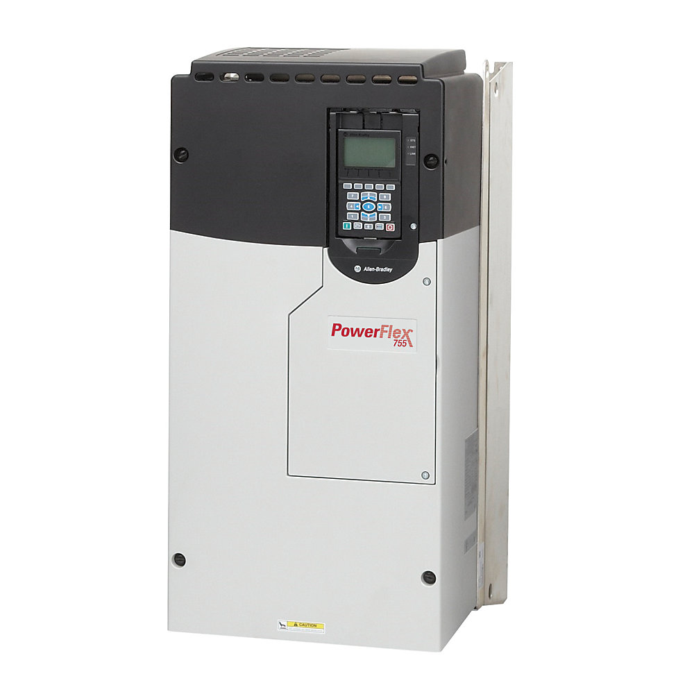
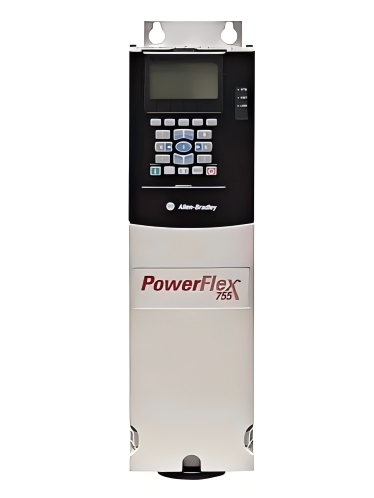
- PowerFlex AC Drive
- USA
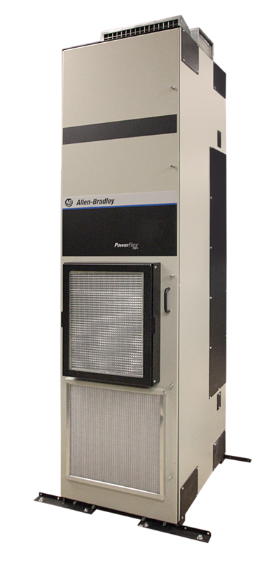
- 2453 × 1200 × 800 mm
- 600kg
- Xiamen, China
- New & In Stock
- T/T, PayPal, Western Union
- 1 Year
- 1-3 Working Days
- DHL, UPS, TNT, FedEx and EMS.
- 24-Hour Service
- COO
- 5
Our advantage

Global Logistics
We have a 10-year logistics and express cooperation agreement, so our products can be shipped to any place in the world.

Brand new and original
Our products are imported in bulk from the place of origin. Because of the cooperative relationship, our products are all original and 100% new.

24-hour service
We provide 7*24 hours service to our customers. We will be there whenever you need us.

Price advantage
All our products are priced very favorably because we have our own warehouse and supply.
| Company Information | |||
| [email protected] | |||
| Mobile | +8615980777398 | ||
| +8615980777398 | |||
| 15980777398 |
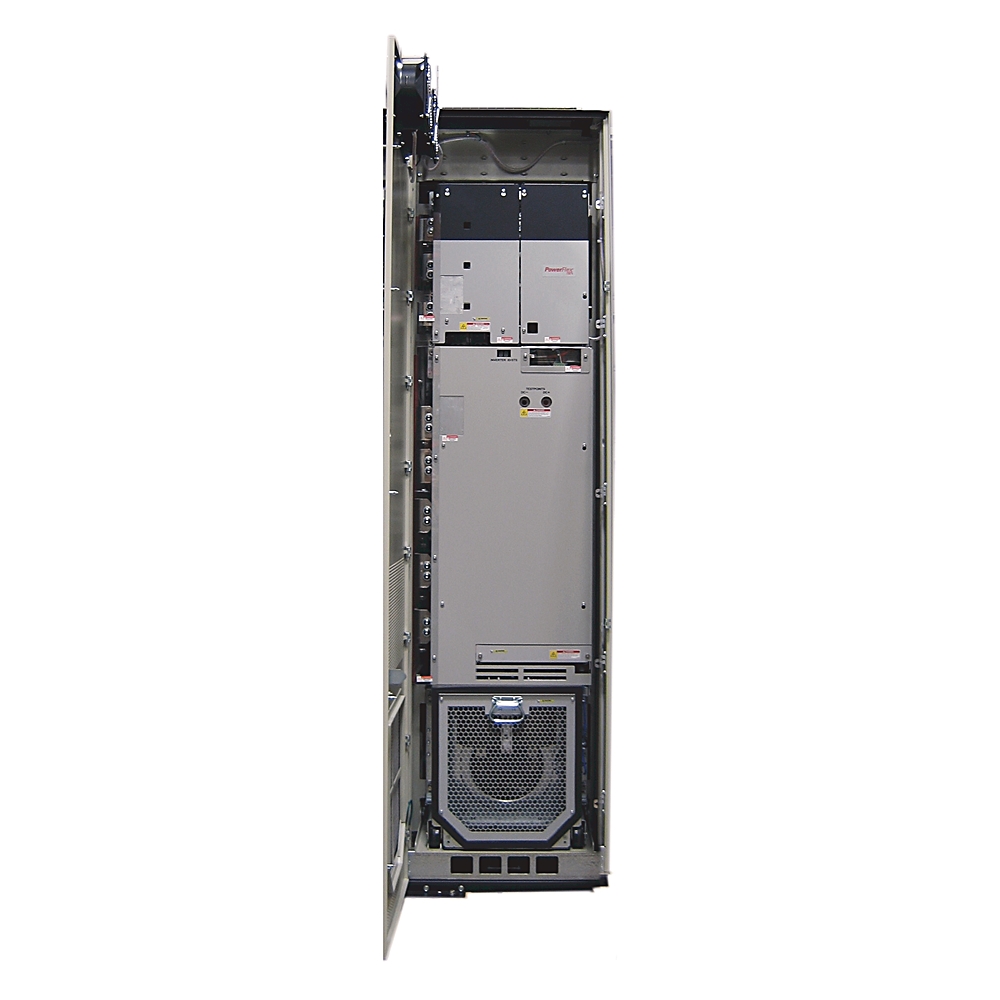
Allen-Bradley 20G1ALF330JN0NNNNN PowerFlex 755 AC Drive
1. Product Overview
The Allen-Bradley 20G1ALF330JN0NNNNN is a high-power PowerFlex 755 AC variable frequency drive designed for demanding three-phase industrial motor applications.
This model is a 690 VAC, 330 A, Frame 8 drive with forced-air cooling, embedded EtherNet/IP communication, AC input with precharge, no DC input terminals, and an IP20 / NEMA Type 1 MCC-style construction.
It is intended for large industrial motors where accurate speed control, controlled acceleration and deceleration, adjustable torque, process regulation, and reliable integration with an industrial control system are required.
The drive is particularly suited to large pumps, fans, blowers, conveyors, compressors, mixers, material-handling equipment, process machinery, and other continuous-duty industrial loads.
The 20G1ALF330JN0NNNNN belongs to the PowerFlex 755 family and uses the Frame 8 mechanical platform. Its 330 A current rating provides substantial motor-control capacity for high-power 690 V systems.
2. Brand and Product Series
| Item | Description |
|---|---|
| Brand | Allen-Bradley |
| Product Series | PowerFlex 755 |
| Product Family | PowerFlex 750-Series |
| Product Type | AC Variable Frequency Drive |
| Model | 20G1ALF330JN0NNNNN |
| Drive Construction | Air-cooled / forced-air |
| Voltage Class | 690 VAC |
| Input | Three-phase AC |
| Frame Size | Frame 8 |
| Cooling | Forced air |
| Communication | Embedded EtherNet/IP |
| Enclosure Style | IP20 / NEMA Type 1 MCC-style |
| Installation Style | MCC-style / floor-mounted industrial installation |
| Dynamic Braking | None in this configuration |
| HIM | Blank / no HIM in the specified configuration |
| DC Terminals | No external DC terminals |
| EMC / Filtering | Filtered configuration with CM jumper installed |
| Main Application | High-power industrial motor speed and torque control |
The PowerFlex 755 series is designed around a modular drive architecture that supports a wide range of motor-control and industrial automation requirements.
The 20G1ALF330JN0NNNNN represents one of the higher-power Frame 8 configurations within the 690 VAC range.
3. Main Technical Parameters
| Parameter | Specification |
|---|---|
| Model | 20G1ALF330JN0NNNNN |
| Brand | Allen-Bradley |
| Series | PowerFlex 755 |
| Drive Type | AC Variable Frequency Drive |
| Rated Input Voltage | 690 VAC |
| Input Phase | 3 Phase |
| Nominal Output Current | 330 A |
| Light-Duty Rating | 355 kW |
| Normal-Duty Rating | 315 kW |
| Heavy-Duty Rating | 250 kW |
| Frame | Frame 8 |
| Frequency Output | Variable-frequency AC output |
| Cooling Method | Forced-air cooling |
| Input Configuration | AC input with precharge |
| DC Terminals | None |
| Communication | Embedded EtherNet/IP |
| Enclosure | IP20 / NEMA Type 1 MCC-style |
| EMC Filtering | Filtered |
| CM Jumper | Installed |
| Dynamic Braking | None |
| HIM | Blank / no HIM |
| Control Capability | Adjustable speed, torque and process control |
| Typical Motor Type | Three-phase AC motor |
| Operating Temperature | Approximately -20 to +60 °C, subject to derating and installation conditions |
| Storage Temperature | Approximately -40 to +70 °C |
| Approx. Height | 2453 mm |
| Approx. Width | 600 mm |
| Approx. Depth | 800 mm maximum for the 800 mm-deep MCC-style configuration |
| Approx. Weight | 623 kg |
| Installation Category | High-power industrial drive installation |
The dimensions and weight above are approximate Frame 8 MCC-style values. Actual shipping weight and mechanical dimensions can vary according to cabinet configuration, options, filter arrangement, and installation accessories.
For equipment lifting, transportation, floor loading, cabinet fabrication, and final mechanical design, the exact mechanical drawing for the ordered configuration should always be used.
4. Electrical Rating
The drive operates on a three-phase 690 VAC supply.
The nominal output current is 330 A, making it suitable for large industrial motors and high-power mechanical systems.
The drive provides three principal application ratings:
| Duty Rating | Power Rating | Typical Use |
|---|---|---|
| Light Duty | 355 kW | Lower overload demand, high-power centrifugal equipment |
| Normal Duty | 315 kW | General industrial applications |
| Heavy Duty | 250 kW | Higher overload and torque requirements |
The distinction between light-duty, normal-duty, and heavy-duty operation is important when selecting a drive for an actual motor.
A motor should not be selected only by comparing the motor nameplate kW with the largest drive kW rating.
The actual application duty cycle, acceleration requirements, overload requirements, operating speed range, ambient temperature, altitude, motor current, and load characteristics must also be considered.
5. 330 A Output Capacity
The 330 A output rating is one of the main characteristics of the 20G1ALF330JN0NNNNN.
For a high-power motor system, available output current is often more important than simply comparing horsepower or kilowatt values.
Motor current increases when the motor operates under heavier mechanical load.
A drive with sufficient current capacity provides additional operating margin and helps maintain controlled motor operation during acceleration, process changes, and temporary load increases.
For this reason, the 330 A rating makes this model appropriate for large industrial machinery rather than small or medium-size motor applications.
6. 690 VAC System Compatibility
The 690 VAC rating makes the drive suitable for high-voltage industrial motor systems.
690 V motor systems are commonly used in large industrial installations because the higher voltage allows high motor power to be transmitted with lower current than an equivalent lower-voltage system.
For a large motor, reducing current can simplify conductor sizing, switching equipment selection, and distribution-system design.
The 20G1ALF330JN0NNNNN therefore fits applications where high motor power and high-voltage industrial distribution are required.
The incoming power system must be checked carefully before installation.
The supply voltage, frequency, short-circuit capacity, protective devices, grounding arrangement, transformer configuration, motor voltage, and applicable electrical standards should all be confirmed.
7. Forced-Air Cooling
The drive uses forced-air cooling.
At this power level, substantial heat is generated by the power conversion system during normal operation.
Forced-air cooling moves air through the power structure and heat-dissipation system to control internal temperature.
Proper airflow is essential.
The installation area should be kept clean and free from excessive dust, conductive particles, corrosive gases, moisture, and other contaminants that could reduce cooling performance or damage electrical components.
Airflow around the drive should not be obstructed.
Cabinet ventilation must be designed so that heated air is not continuously recirculated through the drive.
8. Frame 8 Construction
The 20G1ALF330JN0NNNNN uses Frame 8 construction.
Frame 8 is intended for high-power PowerFlex 755 applications and is physically much larger and heavier than the smaller frame sizes used for lower-power motors.
The Frame 8 structure is designed for industrial installation and service access.
Because of its size and weight, mechanical handling should be planned before installation.
Suitable lifting equipment, floor support, mounting rails, cabinet structure, access clearance, and service space should be considered during the engineering stage.
9. Dimensions and Weight
For the IP20 / NEMA Type 1 MCC-style Frame 8 configuration, the approximate overall mechanical envelope is:
| Mechanical Parameter | Approximate Value |
|---|---|
| Model | 20G1ALF330JN0NNNNN |
| Frame | Frame 8 |
| Height | 2453 mm |
| Width | 600 mm |
| Depth | Up to 800 mm |
| Weight | Approximately 623 kg |
| Construction | IP20 / NEMA Type 1 MCC-style |
| Mounting | Floor / MCC-style |
| Cooling | Forced air |
| Service Requirement | Front and installation-access clearance required |
The approximately 623 kg figure is a Frame 8 MCC-style reference weight and should be treated as an engineering planning value rather than a shipment-specific certified weight.
The actual complete assembly can become considerably heavier when additional cabinets, options, accessories, disconnect equipment, filters, or other equipment are included.
The 800 mm depth is particularly important when planning an MCC lineup or equipment room.
A cabinet or electrical room should provide sufficient clearance for cable routing, ventilation, maintenance, removal of serviceable components, and safe access.
10. Product Introduction
The Allen-Bradley 20G1ALF330JN0NNNNN is designed for applications where a conventional motor starter cannot provide the required level of speed regulation or process control.
Instead of operating a motor continuously at full speed, the drive allows the motor operating speed to be adjusted according to process requirements.
This is particularly useful for variable-torque equipment such as pumps and fans.
The drive can also be used for applications requiring controlled acceleration, controlled deceleration, adjustable torque, speed regulation, and coordinated machine operation.
For large industrial systems, the ability to control motor speed can improve process stability and reduce mechanical stress.
The drive also provides a practical interface between the motor, electrical distribution system, and automation control system.
11. Embedded EtherNet/IP Communication
One of the major features of this configuration is embedded EtherNet/IP communication.
This allows the drive to participate directly in an industrial Ethernet control architecture without requiring a separate basic communication adapter for normal network integration.
The drive can exchange operating data with a supervisory control system, including information such as speed command, actual speed, current, status, fault information, and other drive parameters depending on the configured control architecture.
This is useful for centralized control of large numbers of motors.
For example, a production line can use the control system to issue speed references to multiple drives while receiving operating status and fault information from each drive.
Network integration also reduces the need for extensive hardwired control circuits in applications where digital communication is appropriate.
12. AC Input with Precharge
The specified drive uses an AC input with precharge and does not have external DC input terminals.
The precharge function is important in high-power drive systems because it controls the initial charging process of the DC bus.
Controlled charging reduces the electrical stress that would otherwise occur if the DC bus capacitors were connected directly to the supply without a controlled precharge sequence.
For a large 690 VAC drive, this is an important part of the power-conversion architecture.
The installation should still include properly engineered upstream protection and switching equipment.
13. No Dynamic Braking Transistor
The specified configuration does not include a dynamic braking transistor.
This point should be considered carefully when selecting the drive for applications with high regenerative energy.
Loads with significant inertia can return energy to the drive during rapid deceleration.
Examples include large rotating machinery, certain conveyors, centrifuges, hoists, and other systems where the motor is forced to decelerate quickly.
If an application requires frequent high-energy braking, the braking strategy should be evaluated during system design.
Depending on the application, controlled deceleration, mechanical braking, regenerative equipment, or another braking arrangement may be appropriate.
14. IP20 / NEMA Type 1 MCC-Style Construction
The specified configuration uses an IP20 / NEMA Type 1 MCC-style arrangement.
This type of construction is intended primarily for controlled industrial electrical environments.
It is not intended to be treated as a weatherproof outdoor enclosure.
Where the drive is installed in a dusty, wet, corrosive, or otherwise harsh environment, the surrounding electrical enclosure and environmental-control strategy become important.
The installation should protect the drive from direct water exposure, excessive humidity, conductive contamination, and corrosive substances.
15. Filtered Configuration
The 20G1ALF330JN0NNNNN is specified with filtering and a CM jumper installed.
Filtering can help manage conducted electrical noise associated with variable-frequency drive operation.
Correct grounding and cable installation remain essential.
The use of a drive filter does not eliminate the need for good system wiring practices.
Motor cable routing, cable shielding, grounding, separation from sensitive signal wiring, cabinet bonding, and installation of control cables should all be considered.
16. Typical Applications
16.1 Large Pump Systems
Large centrifugal pumps are one of the most natural applications for a high-power variable frequency drive.
The drive can adjust pump speed according to actual process demand.
Instead of controlling flow primarily by throttling a valve while keeping the motor at full speed, the drive can reduce motor speed when less flow is required.
This can reduce mechanical losses and improve process control.
Typical pump applications include:
- Water treatment systems
- Industrial water circulation
- Cooling-water systems
- Process-water systems
- Chemical process pumps
- Large irrigation systems
- Mining water systems
- Boiler-related circulation systems
- Utility pumping stations
17. Fan and Blower Applications
Large fans and blowers can also benefit from variable-speed operation.
The 20G1ALF330JN0NNNNN can regulate motor speed according to ventilation, air-flow, combustion, or process requirements.
Typical applications include:
- Industrial ventilation
- Process exhaust systems
- Cooling towers
- Furnace air systems
- Combustion air systems
- Large air-handling equipment
- Dust collection systems
- Industrial drying equipment
- Process air systems
Fan applications can benefit significantly from variable-speed control because fan power requirements can decrease substantially as operating speed is reduced.
18. Conveyor Applications
Large conveyors often require controlled acceleration and speed regulation.
The drive can provide a controlled motor speed profile rather than applying full motor speed immediately.
This can reduce mechanical shock to:
- Gearboxes
- Couplings
- Belts
- Rollers
- Shafts
- Conveyor structures
- Product loads
The drive can also allow the conveyor speed to be coordinated with upstream and downstream equipment.
19. Compressor Applications
Large industrial compressors can require substantial motor power.
Variable-speed operation can be useful where compressor capacity needs to follow changing process demand.
Applications may include:
- Industrial air compressors
- Process gas compressors
- Cooling-system compressors
- Production compressors
- Utility compressor systems
Compressor applications require careful consideration of acceleration time, minimum speed, motor cooling, torque demand, process pressure, and compressor-specific operating limits.
20. Mixer and Agitator Applications
Large mixers and agitators often require high starting torque.
The drive can provide controlled acceleration and adjustable operating speed.
This can be useful for:
- Chemical mixing
- Water treatment
- Slurry processing
- Mineral processing
- Food and beverage process equipment
- Industrial batch processing
- Tank agitation
The actual drive rating should be selected according to motor current and torque requirements rather than only motor nameplate power.
21. Process Machinery
The drive is also suitable for many types of large process machinery.
Typical applications can include:
- Material-processing equipment
- Large production machines
- Extrusion-related equipment
- Industrial machinery
- Large material-handling systems
- Manufacturing equipment
- Continuous-process machinery
- High-power auxiliary systems
Where process speed needs to change according to production requirements, variable-frequency control can provide a significant improvement over fixed-speed motor operation.
22. Main Product Advantages
22.1 High-Power Motor Control
The 330 A output rating allows the drive to control large industrial motors.
The 690 VAC system rating also makes it suitable for high-power electrical systems.
22.2 Wide Duty Capability
The drive supports different duty ratings depending on application requirements.
The principal ratings are:
- 355 kW light duty
- 315 kW normal duty
- 250 kW heavy duty
This gives engineers flexibility when matching the drive to different types of mechanical loads.
22.3 Embedded Industrial Ethernet
Embedded EtherNet/IP simplifies integration with an industrial automation network.
The drive can become part of a larger control architecture rather than operating as an isolated motor controller.
22.4 Controlled Acceleration
The drive can accelerate a motor gradually rather than applying the full operating speed immediately.
This can reduce starting shock and mechanical stress.
22.5 Controlled Deceleration
The motor can be decelerated according to a programmed speed profile.
This can improve process control and reduce abrupt mechanical changes.
22.6 Adjustable Speed
Motor speed can be matched to the actual process requirement.
This is especially useful for pumps, fans, blowers, conveyors, and process machines.
22.7 Process Control Capability
The drive can be integrated into closed-loop process-control arrangements where speed or process feedback is used to maintain a desired operating point.
This can be useful for pressure, flow, level, temperature-related process control, and other industrial systems.
23. Energy Management Advantages
Variable-speed operation can reduce unnecessary motor energy consumption.
For variable-torque loads, reducing motor speed can significantly reduce the mechanical power required by the machine.
This is why variable-frequency drives are widely used on large pump and fan systems.
The actual energy savings depend on:
- Motor efficiency
- Pump or fan characteristics
- Operating schedule
- Required process flow
- Required pressure
- Speed range
- Mechanical losses
- System resistance
- Control strategy
The drive itself should therefore be viewed as part of an overall energy-management system rather than as a standalone energy-saving device.
24. Motor Control Advantages
The drive can provide controlled motor operation across a variable speed range.
Depending on the motor and configured control mode, the system can provide:
- Adjustable speed
- Controlled acceleration
- Controlled deceleration
- Torque regulation
- Process feedback control
- Motor protection functions
- Fault monitoring
- Drive status monitoring
- Network-based control
- Operating parameter adjustment
This makes the drive suitable for automated production environments.
25. Maintenance Advantages
A variable-frequency drive provides extensive operating information that can assist maintenance personnel.
Depending on the configuration and control system, useful information can include:
- Motor current
- Output frequency
- Output voltage
- Speed reference
- Actual speed
- Drive status
- Fault condition
- Warning condition
- Operating parameters
- Communication status
This information can make troubleshooting more systematic.
Instead of checking only whether a motor is running or stopped, maintenance personnel can examine the drive’s operating condition and fault information.
26. Typical Industrial Installation
A typical installation for the 20G1ALF330JN0NNNNN can include:
Incoming Power → Protection Equipment → Disconnect / Switching Equipment → PowerFlex 755 Drive → Three-Phase Motor
The drive can also communicate with the automation system through EtherNet/IP.
A simplified control structure may be:
PLC / Control System → EtherNet/IP → PowerFlex 755 → Motor
Feedback and operating data can travel back through the communication network.
The final architecture depends on the application and required control functions.
27. Motor Selection Considerations
When matching a motor to the drive, engineers should check more than motor kW.
Important values include:
- Motor rated voltage
- Motor rated current
- Motor frequency
- Motor speed
- Motor power
- Motor service factor
- Motor cooling method
- Motor insulation system
- Starting torque
- Continuous torque
- Overload requirement
- Acceleration time
- Deceleration time
- Minimum operating speed
- Maximum operating speed
- Application duty cycle
The motor’s full-load current should be compared with the drive’s applicable duty rating.
For demanding constant-torque applications, the heavy-duty rating is particularly important.
28. Recommended Same-Series or Closely Related Models
The following models are closely related PowerFlex 755 configurations and are useful for comparison when selecting a different current or power level.
| Model | Voltage | Current | Light Duty | Normal Duty | Heavy Duty | Frame |
|---|---|---|---|---|---|---|
| 20G1ALF265JN0NNNNN | 690 VAC | 265 A | 315 kW | 250 kW | 200 kW | 8 |
| 20G1ALF330JN0NNNNN | 690 VAC | 330 A | 355 kW | 315 kW | 250 kW | 8 |
| 20G1ALF370JN0NNNNN | 690 VAC | 370 A | 400 kW | 355 kW | 300 kW | 8 |
| 20G1ALF415JN0NNNNN | 690 VAC | 415 A | 450 kW | 400 kW | 355 kW | 8 |
| 20G1ALF460JN0NNNNN | 690 VAC | 460 A | 500 kW | 450 kW | 375 kW | 8 |
These models are useful when the motor current or required power changes while the application remains within the same general PowerFlex 755 high-power 690 V platform.
29. Related Model – 20G1ALF265JN0NNNNN
The 20G1ALF265JN0NNNNN is a lower-current Frame 8 690 VAC configuration.
It is suitable when the connected motor does not require the full 330 A capacity of the target model.
| Parameter | Specification |
|---|---|
| Model | 20G1ALF265JN0NNNNN |
| Series | PowerFlex 755 |
| Voltage | 690 VAC |
| Phase | 3 Phase |
| Current | 265 A |
| Light Duty | 315 kW |
| Normal Duty | 250 kW |
| Heavy Duty | 200 kW |
| Frame | 8 |
| Cooling | Forced air |
| Enclosure | IP20 / MCC-style configuration |
| Typical Dimensions | Approx. Frame 8 envelope |
| Approx. Weight | Approx. 623 kg class for the MCC-style Frame 8 platform |
This model can be considered when a lower current rating is adequate.
30. Related Model – 20G1ALF370JN0NNNNN
The 20G1ALF370JN0NNNNN provides greater current capacity than the 330 A model.
| Parameter | Specification |
|---|---|
| Model | 20G1ALF370JN0NNNNN |
| Series | PowerFlex 755 |
| Voltage | 690 VAC |
| Phase | 3 Phase |
| Current | 370 A |
| Light Duty | 400 kW |
| Normal Duty | 355 kW |
| Heavy Duty | 300 kW |
| Frame | 8 |
| Cooling | Forced air |
| Enclosure | IP20 / MCC-style configuration |
| Dimensions | Approx. 2453 × 600 × 800 mm |
| Approx. Weight | Approx. 623 kg class |
This configuration is useful when a motor requires additional current capacity above the 330 A level.
31. Related Model – 20G1ALF415JN0NNNNN
The 20G1ALF415JN0NNNNN provides another higher-current option within the same 690 VAC Frame 8 family.
| Parameter | Specification |
|---|---|
| Model | 20G1ALF415JN0NNNNN |
| Series | PowerFlex 755 |
| Voltage | 690 VAC |
| Phase | 3 Phase |
| Current | 415 A |
| Light Duty | 450 kW |
| Normal Duty | 400 kW |
| Heavy Duty | 355 kW |
| Frame | 8 |
| Cooling | Forced air |
| Enclosure | IP20 / MCC-style configuration |
| Dimensions | Approx. 2453 × 600 × 800 mm |
| Approx. Weight | Approx. 623 kg class |
This model can be used when the motor rating or process load exceeds the practical range of the 330 A configuration.
32. Related Model – 20G1ALF460JN0NNNNN
The 20G1ALF460JN0NNNNN provides still higher current capacity.
| Parameter | Specification |
|---|---|
| Model | 20G1ALF460JN0NNNNN |
| Series | PowerFlex 755 |
| Voltage | 690 VAC |
| Phase | 3 Phase |
| Current | 460 A |
| Light Duty | 500 kW |
| Normal Duty | 450 kW |
| Heavy Duty | 375 kW |
| Frame | 8 |
| Cooling | Forced air |
| Enclosure | IP20 / MCC-style configuration |
| Dimensions | Approx. 2453 × 600 × 800 mm |
| Approx. Weight | Approx. 623 kg class |
This model is intended for applications requiring substantially higher motor current while remaining within the same general high-power 690 VAC platform.
33. Related Model – 20G1ALF500JN0NNNNN
The 20G1ALF500JN0NNNNN represents a higher-capacity 690 VAC Frame 8 configuration.
| Parameter | Specification |
|---|---|
| Model | 20G1ALF500JN0NNNNN |
| Series | PowerFlex 755 |
| Voltage | 690 VAC |
| Phase | 3 Phase |
| Current | 500 A |
| Light Duty | 530 kW |
| Normal Duty | 500 kW |
| Heavy Duty | 400 kW |
| Frame | 8 |
| Cooling | Forced air |
| Enclosure | IP20 / MCC-style configuration |
| Dimensions | Approx. 2453 × 600 × 800 mm |
| Approx. Weight | Approx. 623 kg class |
It is appropriate to consider this configuration when the connected motor requires more current than the 330 A, 370 A, 415 A, or 460 A configurations can provide.
34. Five Same-Brand Reference Models
The following are useful Allen-Bradley PowerFlex reference models from the broader PowerFlex 755 range.
They cover different current and voltage classes and can be useful when comparing the 20G1ALF330JN0NNNNN with smaller or different-voltage drive configurations.
| Model | Series | Voltage Class | Approx. Current Class | Frame | Typical Application Range |
|---|---|---|---|---|---|
| 20G1ANF061JN0NNNNN | PowerFlex 755 | 690 VAC | 61 A | 6 | Medium-power industrial motors |
| 20G1ANF082JN0NNNNN | PowerFlex 755 | 690 VAC | 82 A | 6 | Pumps, fans, conveyors |
| 20G1ANF098JN0NNNNN | PowerFlex 755 | 690 VAC | 98 A | 6 | Medium-power process equipment |
| 20G1ANB130JA0NNNNN | PowerFlex 755 | 600 VAC class | 130 A | 7 | Industrial motor applications |
| 20G1ALE295JN0NNNNN | PowerFlex 755 | 600 VAC class | 295 A | 8 | Large industrial motors |
These models should be treated as comparison points rather than direct replacements for the 20G1ALF330JN0NNNNN.
Voltage class, current rating, enclosure configuration, frame size, motor duty, braking requirements, communication requirements, and installation method all need to be checked before substitution.
35. Comparison of the Main 690 VAC Models
| Model | Voltage | Current | LD | ND | HD | Frame |
|---|---|---|---|---|---|---|
| 20G1ALF265JN0NNNNN | 690 VAC | 265 A | 315 kW | 250 kW | 200 kW | 8 |
| 20G1ALF330JN0NNNNN | 690 VAC | 330 A | 355 kW | 315 kW | 250 kW | 8 |
| 20G1ALF370JN0NNNNN | 690 VAC | 370 A | 400 kW | 355 kW | 300 kW | 8 |
| 20G1ALF415JN0NNNNN | 690 VAC | 415 A | 450 kW | 400 kW | 355 kW | 8 |
| 20G1ALF460JN0NNNNN | 690 VAC | 460 A | 500 kW | 450 kW | 375 kW | 8 |
| 20G1ALF500JN0NNNNN | 690 VAC | 500 A | 530 kW | 500 kW | 400 kW | 8 |
The progression from 265 A to 500 A provides several options for matching the drive to the motor’s actual current requirements.
36. Application Comparison
| Application | Suitability of 20G1ALF330JN0NNNNN | Main Reason |
|---|---|---|
| Large Pump | High | Adjustable speed and high-power motor control |
| Large Fan | High | Variable-speed operation |
| Blower | High | Speed and process regulation |
| Conveyor | High | Controlled acceleration and speed |
| Compressor | High | Adjustable operating speed |
| Mixer | High | High-power motor and torque control |
| Agitator | High | Controlled speed and process operation |
| Water Treatment | High | Pump and blower control |
| Mining Equipment | High | High-power motor applications |
| Material Handling | High | Large conveyor and mechanical systems |
| Process Machinery | High | Flexible speed control |
| Fixed-Speed Small Motor | Low | Drive capacity is unnecessarily large |
The drive is most appropriate when the connected motor and application require a high-power 690 VAC variable-speed system.
37. Advantages for Pump Systems
For large pumps, the drive can adjust motor speed according to required flow.
This allows the process to operate closer to its actual demand instead of continuously running the pump at maximum speed.
Potential benefits include:
- Reduced throttling losses
- Better flow regulation
- Reduced mechanical stress
- Controlled acceleration
- Controlled stopping
- Improved pressure control
- Easier process automation
- Remote speed adjustment
- Operating-status monitoring
The actual energy savings depend heavily on the hydraulic system and operating profile.
38. Advantages for Fan Systems
Fan systems often operate at different loads throughout the day.
The drive can reduce fan speed when the required airflow decreases.
This can provide:
- Adjustable airflow
- Improved process regulation
- Reduced mechanical stress
- Lower operating speed when demand is low
- Soft starting
- Controlled stopping
- Integration with automation systems
For large ventilation systems, variable-speed control can be particularly useful when airflow demand changes frequently.
39. Advantages for Conveyor Systems
Conveyors often require smooth acceleration.
The drive can gradually increase motor speed rather than applying the full operating speed immediately.
This can reduce shock to the mechanical system.
It can also help synchronize conveyor speed with production machinery.
Typical benefits include:
- Smooth starting
- Adjustable speed
- Reduced belt shock
- Reduced gearbox stress
- Improved product handling
- Process synchronization
- Controlled stopping
- Fault monitoring
40. Advantages for Process Machinery
For process equipment, motor speed can directly affect production quality.
A fixed-speed motor may force operators to regulate the process mechanically.
A variable-frequency drive provides another control variable: motor speed.
This can improve the ability to regulate:
- Flow
- Pressure
- Material movement
- Mixing speed
- Conveyor speed
- Airflow
- Production rate
- Process timing
The result is a more flexible machine-control architecture.
41. Advantages for High-Inertia Loads
Large rotating equipment can have substantial stored mechanical energy.
Starting and stopping such equipment requires careful control.
The drive can provide programmed acceleration and deceleration profiles.
This can reduce sudden torque changes and help protect mechanical components.
High-inertia applications should still be evaluated carefully for braking requirements because the specified model does not include a dynamic braking transistor.
42. Communication and Automation Advantages
Embedded EtherNet/IP makes the drive suitable for networked industrial control.
A control system can potentially monitor:
- Drive status
- Speed command
- Actual speed
- Motor current
- Fault status
- Warning status
- Operating parameters
- Communication status
This can reduce the amount of point-to-point wiring required for some applications.
It also makes centralized motor management more practical in large industrial plants.
43. Maintenance and Troubleshooting
A high-power drive should be incorporated into a structured maintenance program.
Maintenance considerations include:
- Cooling fan condition
- Airflow
- Filter condition
- Cabinet cleanliness
- Electrical connections
- Grounding
- Motor cable condition
- Network connections
- Drive fault history
- Operating temperature
- Motor current
- Mechanical load condition
Dust accumulation is particularly important because it can restrict airflow and increase operating temperature.
Cooling performance should therefore be treated as an important part of preventive maintenance.
44. Installation Environment
Recommended environmental considerations include:
- Clean industrial electrical room
- Controlled humidity
- Limited conductive dust
- Limited corrosive gas exposure
- Adequate ventilation
- Adequate service clearance
- Stable floor support
- Proper grounding
- Correct cable routing
- Suitable upstream protection
The drive should not be installed where water or corrosive chemicals can directly contact the equipment.
45. Mechanical Installation
Because Frame 8 equipment is large and heavy, mechanical installation should be planned before electrical installation begins.
Important considerations include:
- Floor loading
- Lifting points
- Transport path
- Cabinet dimensions
- Door clearance
- Cable-entry location
- Ventilation
- Maintenance clearance
- Removal space
- Front access
- Rear access where required
- Heat dissipation
The approximate weight of the Frame 8 MCC-style drive is around 623 kg, so ordinary manual handling is not appropriate.
A suitable lifting and positioning method should be prepared in advance.
46. Electrical Installation Considerations
The electrical system should include properly sized:
- Incoming conductors
- Protective devices
- Disconnect equipment
- Grounding conductors
- Motor cables
- Control wiring
- Network cables
- Cable glands
- Cabinet ventilation
The motor cable should be selected for the drive output current, installation method, insulation requirements, environmental conditions, and applicable electrical standards.
Long motor cables may also require additional consideration for reflected-wave voltage, cable capacitance, common-mode current, and motor insulation.
47. Motor Cable Considerations
Variable-frequency drives generate high-frequency switching waveforms.
The motor cable therefore forms part of the overall drive system.
Good installation practice can help control electrical noise and common-mode currents.
Important factors include:
- Cable length
- Cable construction
- Shielding
- Grounding
- Cable separation
- Motor insulation
- Output reactor requirements
- Installation environment
- Sensitive nearby equipment
For long-distance motor installations, the complete drive-motor system should be evaluated rather than selecting the cable only according to ampacity.
48. Control System Integration
The drive can be integrated into an industrial automation system using EtherNet/IP.
A typical system can contain:
Operator Interface → Control System → EtherNet/IP Network → PowerFlex 755 → Motor
The operator can issue a speed command through the control system.
The drive receives the command and controls the motor.
The drive can then return status and diagnostic information to the control system.
This architecture is particularly useful when multiple motors must be controlled from one centralized automation system.
49. Product Selection Advantages
The 20G1ALF330JN0NNNNN provides a useful combination of:
- 690 VAC operation
- 330 A output
- 355 kW light-duty capacity
- 315 kW normal-duty capacity
- 250 kW heavy-duty capacity
- Frame 8 construction
- Forced-air cooling
- Embedded EtherNet/IP
- IP20 / NEMA Type 1 MCC-style construction
- AC input with precharge
- Filtered configuration
- CM jumper installed
These characteristics make it suitable for large industrial motor systems where network integration and variable-speed control are required.
50. Key Specification Summary
| Specification | 20G1ALF330JN0NNNNN |
|---|---|
| Brand | Allen-Bradley |
| Series | PowerFlex 755 |
| Product Type | AC Variable Frequency Drive |
| Voltage | 690 VAC |
| Phase | 3 Phase |
| Output Current | 330 A |
| Light Duty | 355 kW |
| Normal Duty | 315 kW |
| Heavy Duty | 250 kW |
| Frame | 8 |
| Cooling | Forced Air |
| Communication | Embedded EtherNet/IP |
| Input | AC Input with Precharge |
| DC Terminals | None |
| Dynamic Braking | None |
| Enclosure | IP20 / NEMA Type 1 MCC-style |
| Filtering | Filtered |
| CM Jumper | Installed |
| HIM | Blank / No HIM |
| Approx. Height | 2453 mm |
| Approx. Width | 600 mm |
| Approx. Depth | 800 mm |
| Approx. Weight | 623 kg |
| Typical Installation | Industrial MCC / Floor-mounted |
| Typical Loads | Pumps, Fans, Blowers, Conveyors, Compressors, Mixers, Process Machinery |
51. Five Closely Related Models – Quick Reference
| Model | Current | LD | ND | HD | Voltage | Frame |
|---|---|---|---|---|---|---|
| 20G1ALF265JN0NNNNN | 265 A | 315 kW | 250 kW | 200 kW | 690 VAC | 8 |
| 20G1ALF330JN0NNNNN | 330 A | 355 kW | 315 kW | 250 kW | 690 VAC | 8 |
| 20G1ALF370JN0NNNNN | 370 A | 400 kW | 355 kW | 300 kW | 690 VAC | 8 |
| 20G1ALF415JN0NNNNN | 415 A | 450 kW | 400 kW | 355 kW | 690 VAC | 8 |
| 20G1ALF460JN0NNNNN | 460 A | 500 kW | 450 kW | 375 kW | 690 VAC | 8 |
52. Five Same-Brand Reference Models – Quick Reference
| Model | Series | Voltage Class | Current | Frame | General Application |
|---|---|---|---|---|---|
| 20G1ANF061JN0NNNNN | PowerFlex 755 | 690 VAC | 61 A | 6 | Medium-power motors |
| 20G1ANF082JN0NNNNN | PowerFlex 755 | 690 VAC | 82 A | 6 | Pumps, fans and conveyors |
| 20G1ANF098JN0NNNNN | PowerFlex 755 | 690 VAC | 98 A | 6 | Process machinery |
| 20G1ANB130JA0NNNNN | PowerFlex 755 | 600 VAC class | 130 A | 7 | Industrial motor control |
| 20G1ALE295JN0NNNNN | PowerFlex 755 | 600 VAC class | 295 A | 8 | Large industrial motors |
53. Overall Product Description
The Allen-Bradley 20G1ALF330JN0NNNNN is a high-capacity PowerFlex 755 AC drive intended for large three-phase 690 VAC motors.
With a 330 A output rating and 355 kW light-duty, 315 kW normal-duty, and 250 kW heavy-duty ratings, it provides a broad operating range for large industrial machinery.
Its Frame 8 construction and forced-air cooling system are designed for high-power industrial installations.
The embedded EtherNet/IP interface allows the drive to be integrated into a networked automation architecture, making it suitable for applications where motor control, monitoring, diagnostics, and process coordination are required.
The AC input with precharge and filtered configuration provide an industrial power-conversion platform suitable for properly engineered high-voltage motor systems.
The drive is particularly well suited to large pumps, fans, blowers, conveyors, compressors, mixers, material-handling equipment, and process machinery.
For mechanical planning, the IP20 / NEMA Type 1 Frame 8 MCC-style configuration has an approximate envelope of 2453 mm high, 600 mm wide, and up to 800 mm deep, with an approximate weight of 623 kg.
Because dimensions and weight can vary with the final cabinet and option configuration, the exact ordered mechanical drawing should be used for final engineering, lifting, transportation, floor-loading, and enclosure design.
54. Final Technical Summary
The 20G1ALF330JN0NNNNN can be summarized as a high-power, three-phase, 690 VAC PowerFlex 755 variable-frequency drive with:
- 330 A output current
- 355 kW light-duty rating
- 315 kW normal-duty rating
- 250 kW heavy-duty rating
- Frame 8 construction
- Forced-air cooling
- Embedded EtherNet/IP
- AC input with precharge
- No external DC terminals
- IP20 / NEMA Type 1 MCC-style construction
- Filtered configuration
- CM jumper installed
- No dynamic braking transistor
- Blank / no HIM configuration
- Approximately 2453 mm height
- Approximately 600 mm width
- Up to approximately 800 mm depth
- Approximately 623 kg Frame 8 MCC-style weight
It is a high-power industrial drive intended for applications where large motors require controlled speed, torque, acceleration, deceleration, process regulation, and integration into an industrial automation network.
For final equipment selection, the most important checks are motor voltage, motor full-load current, duty rating, overload requirement, speed range, braking requirements, environmental conditions, installation dimensions, cooling requirements, and the complete ordered configuration.