

ProductPRODUCT
Featured products
Contact Us
- Allen Bradley
- 20G1ALC650JN4NNNNN
- PowerFlex AC Drive
- USA
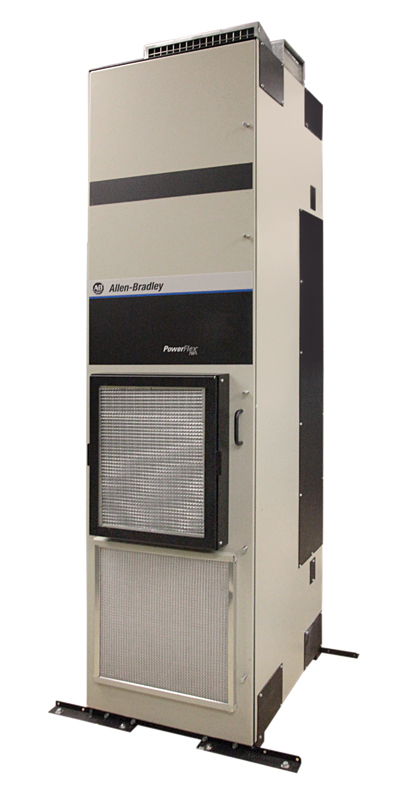
- 2450 × 600 × 800 mm
- 630kg
- Xiamen, China
- New & In Stock
- T/T, PayPal, Western Union
- 1 Year
- 1-3 Working Days
- DHL, UPS, TNT, FedEx and EMS.
- 24-Hour Service
- COO
- 3
Our advantage

Global Logistics
We have a 10-year logistics and express cooperation agreement, so our products can be shipped to any place in the world.

Brand new and original
Our products are imported in bulk from the place of origin. Because of the cooperative relationship, our products are all original and 100% new.

24-hour service
We provide 7*24 hours service to our customers. We will be there whenever you need us.

Price advantage
All our products are priced very favorably because we have our own warehouse and supply.
| Company Information | |||
| [email protected] | |||
| Mobile | +8615980777398 | ||
| +8615980777398 | |||
| 15980777398 |
20G1ALC650JN4NNNNN PowerFlex 755 AC Drive — Detailed Product Profile
1. Product Overview
The 20G1ALC650JN4NNNNN is a high-power air-cooled AC drive in the PowerFlex 755 family, designed for large industrial motor-control applications where high current capacity, reliable speed control, network communication, and practical local operation are required.
This configuration is built around a 400 VAC, three-phase power system and provides a 650 A output-current rating. It uses a Frame 8 power structure and an 800 mm deep MCC-style enclosure, making it a substantial industrial installation rather than a compact machine-mounted variable-frequency drive.
The drive is particularly suitable for large pumps, fans, blowers, conveyors, compressors, process machinery, material-handling systems, and other applications where the motor and mechanical load require a high-capacity industrial VFD.
A major feature of this particular catalog number is its Enhanced LCD, Full Numeric HIM with IP66 / NEMA Type 4X/12 protection. This gives operators and maintenance personnel a convenient local interface while providing a more protected operator-interface arrangement than a basic drive-mounted keypad.
2. Brand and Product Series
| Item | Specification |
|---|---|
| Brand | Allen-Bradley |
| Product Family | PowerFlex |
| Product Series | PowerFlex 755 |
| Product Type | High-Power AC Drive |
| Drive Construction | Air-Cooled Packaged Drive |
| Model | 20G1ALC650JN4NNNNN |
| Frame | Frame 8 |
| Voltage Class | 400 VAC |
| Input | Three Phase |
| Current Rating | 650 A |
| Cooling | Forced Air |
| Enclosure Class | Type 1 / IP20 |
| Cabinet Style | 800 mm Deep MCC Style |
| Network | Embedded EtherNet/IP |
| Local Operator Interface | Enhanced LCD Full Numeric HIM |
| HIM Protection | IP66 / NEMA Type 4X/12 |
| Dynamic Braking | None |
| Input Configuration | AC Input with Precharge |
| DC Terminals | None |
| EMC Configuration | Filtered |
| CM Jumper | Installed |
| Lifecycle Status | Active |
The PowerFlex 755 family is intended for industrial motor applications where the drive needs to provide considerably more than basic frequency control.
It combines motor-control functions with communication, diagnostics, local operation, configurable control functions, and integration into larger automation systems.
3. Main Technical Parameters
| Parameter | Specification |
|---|---|
| Model | 20G1ALC650JN4NNNNN |
| Series | PowerFlex 755 |
| Drive Type | Air-Cooled AC Drive |
| Input Voltage | 400 VAC |
| Input Phase | 3 Phase |
| Rated Output Current | 650 A |
| Light-Duty Rating | 400 kW |
| Normal-Duty Rating | 355 kW |
| Heavy-Duty Rating | 315 kW |
| Frame Size | Frame 8 |
| Input Frequency | 50 / 60 Hz |
| Maximum DC Bus Voltage | Approximately 540 VDC |
| Cooling Method | Forced Air |
| Enclosure | Type 1 / IP20 |
| Cabinet Depth | 800 mm MCC Style |
| Input Configuration | AC Input with Precharge |
| DC Terminals | None |
| Communication | Embedded EtherNet/IP |
| EMC Filtering | Filtered |
| CM Jumper | Installed |
| Dynamic Braking | None |
| Control Methods | V/Hz, Sensorless Vector, Flux Vector |
| HIM | Enhanced LCD, Full Numeric |
| HIM Enclosure Protection | IP66 / NEMA Type 4X/12 |
| Approx. Overall Dimensions | Approximately 2450 × 600 × 800 mm class* |
| Approx. Weight | Approximately 620–630 kg class* |
| Installation | Floor / MCC / Electrical Room |
| Primary Application | Large Industrial Motor Control |
*Physical dimensions and total installed weight can vary with the exact cabinet arrangement, accessories, and mechanical configuration. For engineering layout, lifting, shipping, and foundation work, the final mechanical drawing for the complete configured unit should be treated as the controlling dimension.
4. Electrical Rating
The 650 A output rating is the defining electrical characteristic of this drive.
At this current level, the unit is intended for large industrial motors and substantial mechanical loads.
The drive supports three principal duty levels:
| Duty | Rating |
|---|---|
| Light Duty | 400 kW |
| Normal Duty | 355 kW |
| Heavy Duty | 315 kW |
| Output Current | 650 A |
The different duty ratings are important because motor applications do not all have the same overload requirements.
A pump or fan with relatively smooth loading can often be evaluated under a normal or light-duty profile, while a conveyor, heavy process machine, or other high-torque application may require heavy-duty operation.
The motor’s actual full-load current and overload requirements should always be considered together with the drive rating.
5. 400 VAC Three-Phase Input
The 20G1ALC650JN4NNNNN is designed for a 400 VAC three-phase industrial power supply.
This voltage class is widely used in industrial facilities, process plants, manufacturing systems, infrastructure equipment, and large machine installations.
The drive’s three-phase input architecture provides the power conversion necessary to control large AC motors while allowing the motor speed to be varied according to the requirements of the process.
The input frequency is typically compatible with 50 Hz or 60 Hz industrial power systems, subject to the complete system configuration.
6. AC Input with Precharge
The drive uses an AC input with precharge arrangement.
Precharge is particularly important in high-power drives because the internal DC-link capacitors represent a substantial electrical load when the drive is first energized.
The precharge function helps manage the initial charging process and prevents an uncontrolled inrush condition from being imposed directly on the internal DC bus.
This is an important part of the architecture of a large industrial VFD.
7. No DC Terminals
This particular configuration does not provide conventional external DC terminals.
That means it should not automatically be treated as a drive intended for a shared DC-bus architecture.
If a project requires common DC-bus operation, regenerative operation, or energy sharing between multiple drives, the system configuration needs to be evaluated separately.
8. Embedded EtherNet/IP
One of the most useful features of this drive is its embedded EtherNet/IP communication capability.
The drive can therefore become an active component of a larger industrial automation network rather than operating as an isolated motor controller.
Typical information exchanged with a control system can include:
- Start and stop commands
- Speed references
- Direction commands
- Actual motor speed
- Output frequency
- Motor current
- Drive status
- Alarm conditions
- Fault information
- Operating feedback
- Diagnostic information
This type of communication is particularly useful in large facilities where many drives are supervised by a central PLC or automation system.
9. Enhanced LCD Full Numeric HIM
The JN4 configuration is particularly notable because it includes an Enhanced LCD Full Numeric HIM.
HIM stands for Human Interface Module.
For a large industrial drive, the local operator interface can be extremely useful during installation, commissioning, troubleshooting, and routine maintenance.
The Enhanced LCD interface gives technicians access to drive information and parameters without requiring every adjustment to be made from a remote automation system.
10. IP66 / NEMA Type 4X/12 HIM
The HIM itself has a higher environmental protection level than the basic drive enclosure.
The configuration uses an IP66 / NEMA Type 4X/12 HIM.
This is useful when the operator interface needs additional protection from dust, moisture, splashing, and demanding industrial surroundings.
It is important to distinguish the protection rating of the HIM from the protection rating of the complete drive cabinet.
The main drive enclosure remains a Type 1 / IP20 configuration, while the local operator interface has its own higher protection classification.
11. Enclosure and Mechanical Construction
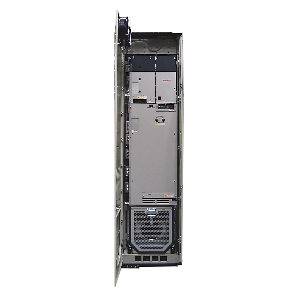
The drive uses a large Frame 8 power structure and an 800 mm deep MCC-style cabinet configuration.
This construction is intended for industrial electrical-room or MCC applications.
Unlike a small VFD that can often be mounted directly onto a machine panel, this drive requires considerably more attention to floor space, ventilation, cable routing, lifting, and service access.
A typical installation should provide sufficient clearance around the equipment for maintenance and safe operation.
12. Approximate Dimensions and Weight
The 20G1ALC650JN4NNNNN is a large piece of industrial electrical equipment.
For planning purposes, the complete drive assembly can be treated as approximately 2450 mm high × 600 mm wide × 800 mm deep, with a total equipment weight in the 620–630 kg range, depending on the exact mechanical configuration.
| Physical Parameter | Approximate Value |
|---|---|
| Model | 20G1ALC650JN4NNNNN |
| Height | Approx. 2450 mm |
| Width | Approx. 600 mm |
| Depth | Approx. 800 mm |
| Approx. Weight | Approx. 620–630 kg |
| Cabinet Style | MCC Style |
| Frame | Frame 8 |
| Cooling | Forced Air |
| Enclosure | Type 1 / IP20 |
| Installation | Floor / Electrical Room |
For a production installation, these values should be treated as planning figures rather than fabrication dimensions.
The final mechanical drawing should be checked before preparing the foundation, cable trench, lifting equipment, access doors, or electrical-room layout.
13. Cooling System
The 20G1ALC650JN4NNNNN uses forced-air cooling.
A 650 A industrial drive can generate a considerable amount of heat during operation.
The forced-air cooling system moves air through the power section and removes heat from the internal components.
For this reason, the installation environment must provide sufficient ventilation.
When several high-power drives are installed in the same electrical room, the combined heat output can become a significant HVAC consideration.
14. EMC Filtering
The drive uses a filtered configuration with the CM jumper installed.
EMC considerations become increasingly important as drive power increases.
The switching action of a VFD produces high-frequency electrical components that can affect surrounding equipment if installation practices are poor.
Correct grounding, motor-cable selection, cable routing, shielding, cabinet bonding, and installation technique are therefore still important.
The integrated filtering is part of the overall EMC design, but it does not eliminate the need for proper installation practices.
15. Dynamic Braking
This configuration is specified with no integrated dynamic braking.
This is an important point when the drive is being selected for machinery with substantial rotating inertia.
During deceleration, a motor can return energy to the drive’s DC bus.
If the application requires rapid stopping, frequent deceleration, or controlled braking of a high-inertia load, the overall braking strategy needs to be considered during system design.
Depending on the application, controlled deceleration, external braking equipment, regenerative technology, or another energy-management solution may be appropriate.
16. Motor Control
The drive can support several industrial motor-control approaches, including:
| Control Method | Typical Use |
|---|---|
| V/Hz | General-purpose motor control |
| Sensorless Vector | Improved speed and torque control without encoder feedback |
| Flux Vector | Higher-performance motor control |
| Closed-Loop Applications | Systems using feedback devices and appropriate options |
The actual control strategy should be selected according to the motor type, load characteristics, speed range, torque requirement, feedback requirements, and process-control objectives.
17. Product Introduction
The 20G1ALC650JN4NNNNN is designed for applications where motor power and current requirements are beyond the range of small and medium industrial drives.
Its 650 A capacity gives it enough electrical headroom for large motor systems while maintaining the control and communication functions expected from a modern industrial drive.
The product is particularly useful where the motor needs controlled acceleration, controlled deceleration, adjustable speed, process-based speed regulation, or communication with a centralized control system.
Its packaged design also makes it suitable for large electrical rooms and MCC-style installations.
18. How the Drive Controls a Motor
The drive receives three-phase AC power from the industrial electrical system.
Internally, the drive converts and regulates electrical energy before producing a controlled variable-frequency output for the motor.
Changing the output frequency changes the operating speed of the motor.
The drive can also regulate voltage and current according to the selected motor-control strategy.
This makes it possible to control a motor according to actual process requirements rather than simply operating the motor at full speed continuously.
For example, a large pump may need full output at one point in the process and substantially lower speed at another point.
A variable-frequency drive allows the motor speed to follow the process demand.
19. Main Applications
Large Pumps
Large pumps are one of the most natural applications for a high-current AC drive.
Pump systems often operate under changing flow requirements.
Instead of running the motor continuously at maximum speed, the drive can adjust the motor speed to suit the required flow and pressure.
This can also reduce mechanical stress on the pump system.
Fans and Blowers
Industrial fans and blowers frequently require variable airflow.
The drive can adjust motor speed according to temperature, pressure, production rate, or ventilation requirements.
The high-current rating makes this configuration suitable for large industrial fan systems.
Conveyors
Large conveyors can require significant torque during starting and acceleration.
The drive provides controlled acceleration rather than applying full line power directly to the motor.
This can reduce mechanical shock and make the movement of heavy material more controlled.
Compressors
Industrial compressors can have substantial motor requirements and may benefit from controlled starting and adjustable speed.
The suitability of a specific drive configuration depends on compressor type, load profile, required speed range, and process requirements.
Process Machinery
The drive can also be used in process machinery where motor speed needs to be coordinated with production conditions.
Examples include mixers, rotating process equipment, feeders, production machinery, and large material-processing systems.
Material Handling
High-power material-handling systems can use this type of drive for large conveyors, feeders, and other rotating equipment.
EtherNet/IP communication can be useful where several motors need to be coordinated by a common control system.
20. Application Comparison
| Application | Main Requirement | Why This Drive Fits |
|---|---|---|
| Large Pumps | Variable flow and speed | High current and variable-speed control |
| Industrial Fans | Adjustable airflow | Large motor capacity |
| Blowers | Continuous-duty speed control | High-power operation |
| Conveyors | Controlled acceleration | High current and torque control |
| Compressors | Stable motor operation | Large motor capability |
| Process Machinery | Coordinated speed | Network communication |
| Material Handling | High starting demand | Large current capacity |
| Production Lines | Networked motor control | Embedded EtherNet/IP |
| Utility Equipment | Continuous operation | Industrial packaged construction |
| Large Rotating Machinery | High-power control | 650 A output capability |
21. Main Product Advantages
21.1 High 650 A Current Rating
The 650 A rating gives this drive substantial capacity for large industrial motors.
It is designed for applications where a compact VFD would not provide enough current.
21.2 400 kW Light-Duty Capacity
The light-duty rating reaches the 400 kW class, making this a substantial high-power drive.
This provides a broad application range for industrial equipment with relatively smooth load characteristics.
21.3 355 kW Normal-Duty Rating
The 355 kW normal-duty rating provides a strong operating point for large industrial motors.
It is appropriate for many continuous-duty applications where the load profile does not require the more demanding heavy-duty overload characteristics.
21.4 315 kW Heavy-Duty Rating
For more demanding applications, the drive provides a 315 kW heavy-duty rating.
This rating is particularly relevant when the load requires higher torque or more significant overload capability.
21.5 Embedded EtherNet/IP
Integrated EtherNet/IP communication allows the drive to be incorporated into a larger automation architecture.
This is useful for centralized monitoring, PLC control, diagnostics, and coordinated operation.
21.6 Enhanced Local Operator Interface
The Enhanced LCD Full Numeric HIM provides convenient access to operating information and configuration parameters.
For large drives, this can save considerable time during commissioning and maintenance.
21.7 Higher-Protected HIM
The IP66 / NEMA Type 4X/12 HIM provides additional protection at the operator interface.
This makes the local interface better suited to demanding industrial environments than a basic exposed operator panel.
21.8 Forced-Air Cooling
Forced-air cooling provides a practical thermal-management solution for the high-power electrical section.
It is well suited to controlled industrial electrical rooms where ventilation can be properly engineered.
21.9 Industrial Packaged Construction
The large packaged construction provides a more complete industrial installation solution than a small standalone inverter.
This is particularly useful for large plants and MCC-based electrical systems.
22. Five Related PowerFlex 755 Models
The following models are useful comparison models within the same high-power family.
| Model | Series | Current | Voltage Class | LD Rating | ND Rating | HD Rating | Cooling |
|---|---|---|---|---|---|---|---|
| 20G1ALC567JN4NNNNN | PowerFlex 755 | 567 A | 400 VAC | Configuration dependent | Configuration dependent | Configuration dependent | Forced Air |
| 20G1ALC650JN4NNNNN | PowerFlex 755 | 650 A | 400 VAC | 400 kW | 355 kW | 315 kW | Forced Air |
| 20G1ALC750JN4NNNNN | PowerFlex 755 | 750 A | 400 VAC | 450 kW | 400 kW | 315 kW | Forced Air |
| 20G1ALC770JN4NNNNN | PowerFlex 755 | 770 A | 400 VAC | 450 kW | 400 kW | 355 kW | Forced Air |
| 20G1ALD710JN4NNNNN | PowerFlex 755 | 710 A class | 400 V class | 650 HP class | 600 HP class | 450 HP class | Forced Air |
These models are useful when selecting a drive around the 650 A range.
The 567 A configuration represents a lower-current option, while the 750 A and 770 A configurations move toward a higher-current and higher-power class.
The 710 A configuration provides another nearby high-power option with a different catalog configuration.
23. Related Model Physical and Technical Comparison
| Parameter | 20G1ALC567JN4NNNNN | 20G1ALC650JN4NNNNN | 20G1ALC750JN4NNNNN | 20G1ALC770JN4NNNNN | 20G1ALD710JN4NNNNN |
|---|---|---|---|---|---|
| Series | PowerFlex 755 | PowerFlex 755 | PowerFlex 755 | PowerFlex 755 | PowerFlex 755 |
| Current | 567 A | 650 A | 750 A | 770 A | 710 A class |
| Voltage | 400 VAC | 400 VAC | 400 VAC | 400 VAC | 400 V class |
| Cooling | Forced Air | Forced Air | Forced Air | Forced Air | Forced Air |
| EtherNet/IP | Yes | Yes | Yes | Yes | Yes |
| Frame | High-Power Frame | Frame 8 | High-Power Frame | High-Power Frame | High-Power Frame |
| HIM | Enhanced LCD configuration | Enhanced LCD Full Numeric | Enhanced LCD configuration | Enhanced LCD configuration | Enhanced LCD configuration |
| Main Enclosure | IP20 / Type 1 | IP20 / Type 1 | IP20 / Type 1 | IP20 / Type 1 | IP20 / Type 1 |
| Cabinet Depth | MCC style | 800 mm | MCC style | MCC style | MCC style |
| Dimensions | Configuration dependent | Approx. 2450 × 600 × 800 mm | Configuration dependent | Configuration dependent | Configuration dependent |
| Weight | Configuration dependent | Approx. 620–630 kg | Configuration dependent | Configuration dependent | Configuration dependent |
The complete catalog number matters when comparing these products.
Two drives can have similar electrical ratings but different operator-interface configurations, enclosure options, braking arrangements, filtering options, or mechanical constructions.
24. Five Popular Models from the Same Brand
For a broader comparison, the following models represent commonly encountered drive families at different power levels.
| Model | Product Family | General Power Class | Typical Application | Main Characteristics |
|---|---|---|---|---|
| 25B-D010N104 | PowerFlex 525 | Small / Low Power | Compact machines | Compact variable-frequency drive |
| 25C-D010N103 | PowerFlex 527 | Small to Medium | Machine automation | Network-oriented machine drive |
| 20F11NC2P1JA0NNNNN | PowerFlex 753 | Medium Industrial | Pumps, fans, machinery | Flexible industrial drive |
| 20F11NC8P0JA0NNNNN | PowerFlex 753 | Medium / High | Industrial equipment | Higher-capacity industrial drive |
| 20G1ALC650JN4NNNNN | PowerFlex 755 | High Power | Large industrial systems | 400 VAC, 650 A packaged drive |
These products cover a wide range of industrial drive applications.
The PowerFlex 525 and PowerFlex 527 families are generally more suitable for smaller machine applications.
The PowerFlex 753 family extends into larger industrial systems.
The PowerFlex 755 family is intended for high-performance and high-power applications, with the 20G1ALC650JN4NNNNN sitting firmly in the large-drive category.
25. Brand Model Comparison
| Model | Series | Current / Size Class | Typical Application | Installation Scale |
|---|---|---|---|---|
| 25B-D010N104 | PowerFlex 525 | Low | Machine automation | Compact |
| 25C-D010N103 | PowerFlex 527 | Low / Medium | Machine control | Compact |
| 20F11NC2P1JA0NNNNN | PowerFlex 753 | Medium | Industrial machinery | Medium |
| 20F11NC8P0JA0NNNNN | PowerFlex 753 | Medium / High | Industrial equipment | Large |
| 20G1ALC650JN4NNNNN | PowerFlex 755 | 650 A | Large industrial equipment | Very Large |
26. Why the 20G1ALC650JN4NNNNN Is a High-Power Drive
The 650 A output rating is the clearest indication of the scale of this product.
At 650 A, the drive is not intended for ordinary small motors or compact machines.
It belongs in large industrial applications where the motor itself may represent a significant portion of the plant’s mechanical capacity.
The electrical installation therefore needs to be engineered around high-current conductors, appropriate protection, thermal management, grounding, motor cables, and mechanical access.
27. Importance of Duty Selection
One of the most common mistakes in drive selection is looking only at the motor’s nominal kW rating.
The motor may have one nameplate power, but the drive’s actual required capacity depends on how the motor is used.
For example, a conveyor that repeatedly starts with a heavy load can place substantially greater demands on the drive than a large fan that accelerates slowly and then runs at a relatively stable load.
This is why the 400 kW LD, 355 kW ND, and 315 kW HD ratings should be considered separately.
28. Installation Planning
Because this is a large Frame 8 drive, the installation should be planned before the equipment arrives.
Important considerations include:
- Floor loading
- Cabinet location
- Lifting access
- Cable entry
- Motor cable routing
- Input cable routing
- Grounding
- Ventilation
- Service clearance
- Operator access
- Network cable routing
- Heat dissipation
- Maintenance access
The approximate 620–630 kg equipment weight means that normal manual handling is not appropriate.
Suitable lifting and positioning equipment should be planned as part of the installation.
29. Electrical Room Requirements
A large drive installation can generate substantial heat.
The electrical room should therefore be designed so that hot exhaust air does not simply circulate back into the drive’s cooling intake.
When several high-power drives are installed in the same room, the combined thermal load can be significant.
Ventilation should be evaluated according to the actual number of drives, operating load, ambient temperature, room volume, and HVAC strategy.
30. Maintenance
Regular inspection of the cooling system is important.
Air filters, ventilation paths, fans, electrical connections, and enclosure areas should be kept in suitable condition.
Technicians should also monitor unusual fan noise, temperature increases, repeated drive faults, unexpected current changes, and abnormal motor behavior.
The local Enhanced LCD HIM is useful for troubleshooting because it gives maintenance personnel direct access to drive information.
The embedded communication interface also allows higher-level systems to monitor the drive remotely.
31. Typical Industrial Applications
| Industry | Equipment | Typical Drive Function |
|---|---|---|
| Water & Wastewater | Large Pumps | Flow / pressure control |
| Manufacturing | Conveyors | Speed and torque control |
| Mining | Conveyors / Material Handling | High-power motor control |
| Chemical Processing | Pumps / Mixers | Process speed control |
| Cement | Fans / Conveyors | Variable-speed operation |
| Metals | Production Equipment | High-performance motor control |
| Utilities | Pumps / Fans | Continuous-duty operation |
| HVAC Infrastructure | Large Fans / Blowers | Airflow control |
| Material Handling | Conveyors / Feeders | Controlled acceleration |
| Process Industries | Large Rotating Equipment | Coordinated motor control |
32. Advantages in Automation Systems
The drive is not simply a power converter.
In a modern industrial automation system, the drive can serve as an intelligent motor-control node.
The embedded network allows the PLC to issue commands and receive operating feedback.
This can reduce the amount of traditional point-to-point control wiring required for drive monitoring.
It also makes it easier to collect diagnostic information from the drive.
For large plants, this can become particularly valuable because maintenance teams may need to monitor many motor systems from a central control environment.
33. Advantages of the Enhanced HIM
The local HIM is especially useful during commissioning.
A technician can stand directly at the drive and check operating parameters without depending entirely on a remote workstation.
It can also be useful when troubleshooting a fault.
Instead of simply seeing that a motor has stopped, the technician can investigate drive status, alarms, parameters, and other operating information locally.
The higher protection level of the HIM also makes the operator interface better suited to demanding industrial environments.
34. Advantages of the 800 mm MCC-Style Construction
The 800 mm deep MCC-style construction provides the physical space required for a high-power drive architecture.
Large power components require more space than compact VFDs.
The larger enclosure can provide room for power connections, cooling paths, control hardware, and service access.
For plant designers, this can make the drive easier to integrate into a dedicated electrical-room or MCC arrangement.
35. Product Selection Checklist
| Selection Factor | Requirement |
|---|---|
| Input Voltage | 400 VAC class |
| Input Phase | Three Phase |
| Motor Current | Must remain within applicable drive rating |
| Motor Power | Check LD / ND / HD rating |
| Load Type | Determine pump, fan, conveyor, compressor, etc. |
| Overload | Determine required duty |
| Braking | Confirm whether dynamic braking is required |
| Regeneration | Determine whether regenerated energy exists |
| Cooling | Confirm adequate airflow |
| Installation | Confirm Frame 8 cabinet space |
| Weight | Plan for approximately 620–630 kg |
| Dimensions | Allow approximately 2450 × 600 × 800 mm class |
| Communication | Confirm EtherNet/IP requirements |
| Local Interface | Confirm Enhanced LCD HIM requirement |
| Environment | Suitable indoor electrical environment |
| Maintenance | Provide sufficient access |
| Cable Routing | Plan high-current input and motor cables |
36. Technical Summary Table
| Category | Specification |
|---|---|
| Model | 20G1ALC650JN4NNNNN |
| Brand | Allen-Bradley |
| Series | PowerFlex 755 |
| Product Type | High-Power AC Drive |
| Construction | Packaged Air-Cooled Drive |
| Input Voltage | 400 VAC |
| Input | 3 Phase |
| Current | 650 A |
| Light Duty | 400 kW |
| Normal Duty | 355 kW |
| Heavy Duty | 315 kW |
| Input Frequency | 50 / 60 Hz |
| Maximum DC Bus | Approx. 540 VDC |
| Frame | Frame 8 |
| Cooling | Forced Air |
| Enclosure | Type 1 / IP20 |
| Cabinet Depth | 800 mm MCC Style |
| Communication | Embedded EtherNet/IP |
| EMC | Filtered |
| CM Jumper | Installed |
| Dynamic Braking | None |
| DC Terminals | None |
| Input | AC with Precharge |
| HIM | Enhanced LCD Full Numeric |
| HIM Protection | IP66 / NEMA Type 4X/12 |
| Control | V/Hz / Sensorless Vector / Flux Vector |
| Approx. Dimensions | 2450 × 600 × 800 mm class |
| Approx. Weight | 620–630 kg class |
| Main Application | Large Industrial Motor Control |
37. Final Product Description
The 20G1ALC650JN4NNNNN is a large-capacity PowerFlex 755 AC drive designed for demanding industrial motor-control applications.
Its 400 VAC three-phase input, 650 A output rating, 400 kW light-duty rating, 355 kW normal-duty rating, and 315 kW heavy-duty rating place it firmly in the high-power industrial drive category.
The unit combines high-current motor control with embedded EtherNet/IP communication, forced-air cooling, EMC filtering, an AC input with precharge, and a Frame 8 packaged construction.
The Enhanced LCD Full Numeric HIM is one of the most useful characteristics of the JN4 configuration. Its IP66 / NEMA Type 4X/12 protection provides a robust local operator interface for commissioning and maintenance.
The drive’s Type 1 / IP20, 800 mm deep MCC-style enclosure is designed for a controlled industrial electrical environment rather than direct exposure to outdoor conditions.
With an approximate physical size in the 2450 × 600 × 800 mm class and an approximate installed weight of 620–630 kg, the drive requires proper mechanical planning, lifting arrangements, floor support, ventilation, cable routing, and maintenance access.
The 650 A capacity makes it suitable for large pumps, fans, blowers, conveyors, compressors, process equipment, material-handling machinery, utility equipment, and other high-power rotating machinery.
The combination of local operator control and embedded EtherNet/IP also makes it practical for plants where large motors need to be integrated into a centralized automation architecture.
When selecting or replacing this drive, the complete catalog number should be matched rather than comparing only the 650 A rating. The HIM configuration, enclosure, filtering, braking arrangement, cooling system, power structure, and other catalog options can all affect the final equipment configuration.
Overall, the 20G1ALC650JN4NNNNN is best viewed as a complete high-power industrial motor-control solution for large-scale equipment, especially where high current, network integration, local operator access, and packaged MCC-style construction are important.