
NewsNEWCENTER
Featured products
Contact Us
Allen-Bradley 1756-IF8H ControlLogix HART Analog Input Module – Installation and Configuration Guide
2026-11-16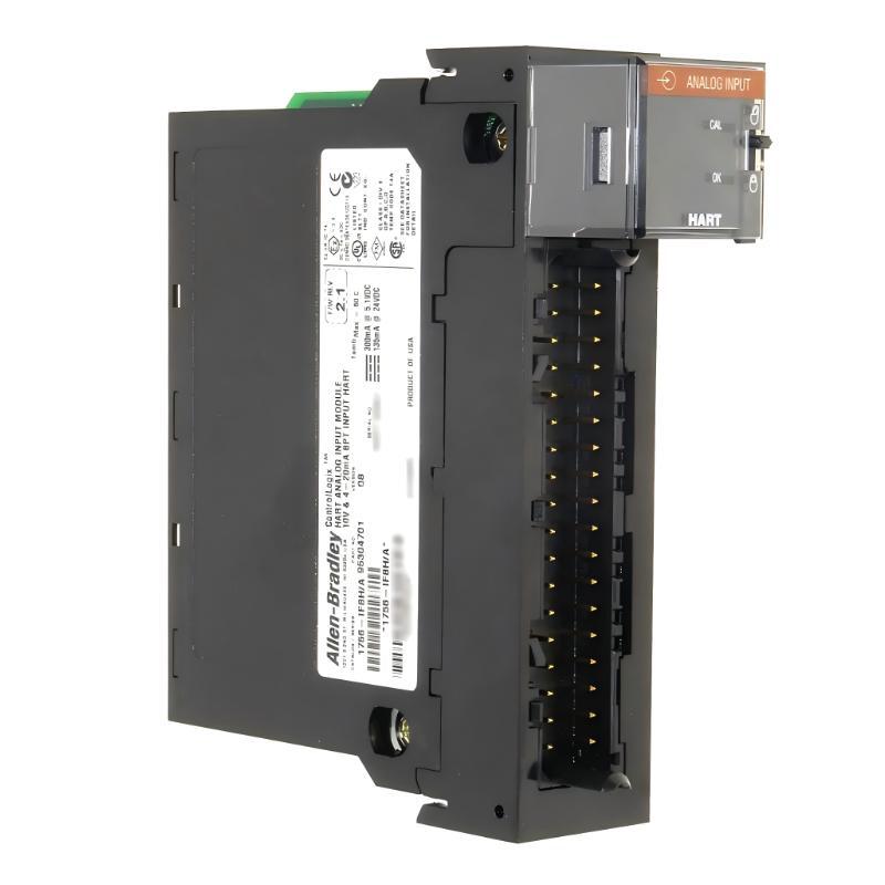
1. Product Introduction
The Allen-Bradley 1756-IF8H is an eight-channel analog input module designed for ControlLogix automation systems. It accepts differential voltage and current signals from industrial transmitters and converts them into measurement data for processing by a Logix 5000 controller. With HART protocol support, the module can also provide access to digital instrument information from compatible field devices.
The 1756-IF8H is commonly used in process industries where accurate acquisition of pressure, temperature, flow, level, and other process variables is required. Its eight input channels support several standard voltage and current ranges, including 4–20 mA signals widely used in industrial instrumentation.
Installation involves mounting the module in a compatible ControlLogix chassis, connecting the field transmitters through the appropriate removable terminal block (RTB), configuring channel characteristics in the controller project, and verifying both analog measurements and HART communication.
2. Main Features and Functional Overview
- Eight differential analog input channels.
- Supports voltage and current signal measurement.
- Accepts common ranges including ±10 V, 0–5 V, 1–5 V, 0–10 V, 0–20 mA, and 4–20 mA.
- Supports HART communication with compatible field instruments.
- Provides analog measurement data for Logix 5000 controllers.
- Designed for installation in a compatible ControlLogix 1756 chassis.
- Uses a 36-pin removable terminal block connection arrangement.
One important consideration is the hardware series. Series A and Series B versions have different HART modem arrangements. Series A uses one HART modem per module, while Series B provides one HART modem per channel. Confirm the installed series before planning instrument communication or replacing an existing module.
3. Pre-Installation Preparation
Before installing the 1756-IF8H, check the ControlLogix hardware, field instrument requirements, and existing controller configuration. A correct installation begins with confirming that the module and its associated terminal block are suitable for the application.
Hardware Compatibility
- Confirm that the module catalog number is 1756-IF8H.
- Identify the hardware series and revision from the module label.
- Verify that the ControlLogix chassis supports the module.
- Check that the required 36-pin RTB and terminal housing are available and compatible.
- Confirm that the controller firmware and engineering software support the selected module profile.
- Review the system design for channel allocation and HART instrument requirements.
Field Instrument Checks
Prepare a list of the transmitters connected to the eight input channels. Record each instrument’s signal type, measurement range, wiring arrangement, power source, and HART requirements.
| Signal Type | Typical Application | Configuration Consideration |
|---|---|---|
| 4–20 mA | Pressure, flow, temperature, and level transmitters | Confirm current input mode and engineering range |
| 0–20 mA | General industrial current measurement | Verify transmitter output range and channel scaling |
| 0–10 V | Voltage-output sensors and signal conditioners | Confirm voltage input selection and polarity |
| 1–5 V | Conditioned process measurement signals | Check transmitter output and controller scaling |
| 0–5 V | Low-voltage analog instrumentation | Verify the correct input range |
| ±10 V | Bipolar analog measurement applications | Check positive and negative signal connections |
Do not assume that all eight channels use the same signal type. Each channel should be configured according to the connected instrument and the approved control system design.
4. Safety Precautions Before Installation
Installation and wiring should be carried out by qualified personnel familiar with ControlLogix systems and industrial instrumentation. Follow the site’s electrical safety procedures and the applicable module installation instructions.
- Place the controlled process in an approved maintenance condition.
- Apply lockout/tagout procedures where required.
- Verify that field circuits are isolated before changing wiring.
- Use appropriate electrostatic discharge protection when handling the module.
- Avoid touching the module’s backplane connector or exposed electronic components.
- Do not connect or disconnect the RTB while energized unless the exact system documentation and approved procedure permit it.
- Check field instrument power sources before connecting signal conductors.
- Never apply a voltage or current outside the module’s specified input limits.
5. Installing the 1756-IF8H in the ControlLogix Chassis
Step 1: Prepare the Chassis
Confirm that the ControlLogix chassis is installed securely and that its power supply is operating within the required system specifications. Identify the slot assigned to the 1756-IF8H using the electrical drawings and controller project.
Step 2: Inspect the Module
Examine the module housing, backplane connector, and front-panel components. Check for damaged contacts, cracks, contamination, or signs of overheating. Verify the catalog number and series before proceeding.
Step 3: Insert the Module
Align the module with the chassis guides and slide it into the selected slot. Ensure that it is fully seated and secured according to the ControlLogix chassis procedure. Do not force the module into position if resistance is encountered.
Step 4: Prepare the Removable Terminal Block
Confirm that the RTB and terminal housing are the correct components for the module. Inspect the terminal block for damaged contacts, loose screws, and incorrect keying. The terminal block provides the field wiring interface, so its compatibility and mechanical condition are important for reliable signal acquisition.
6. Field Wiring and Signal Connections
The 1756-IF8H uses differential input connections. Each channel has positive and negative signal terminals, while the RTB provides additional connections for current-return and related wiring arrangements. Use the wiring diagram for the exact module series and terminal block before connecting field conductors.
Two-Wire Current Transmitters
A two-wire transmitter normally receives power through its current loop. Connect the transmitter and external loop power supply according to the approved wiring diagram. Confirm the current path and polarity before energizing the circuit.
For a typical 4–20 mA instrument, verify that the transmitter output, loop supply, and module input are arranged as one complete current loop. Incorrect polarity or an incomplete loop can result in a zero reading, an out-of-range value, or an instrument fault.
Four-Wire Current Transmitters
A four-wire transmitter generally uses a separate power supply for the instrument electronics and provides an independent current output. Connect the transmitter output to the appropriate differential input terminals. Confirm the transmitter’s output wiring and common-reference arrangement before applying power.
Voltage Inputs
For voltage signals, connect the positive and negative conductors to the corresponding differential input terminals. Verify the voltage range and polarity. Do not connect a voltage source to a channel configured for an incompatible signal type.
Wiring Inspection Checklist
- Confirm the channel number for every transmitter.
- Check the positive and negative input conductors.
- Verify the external power supply arrangement for each instrument.
- Separate low-level analog wiring from high-voltage power wiring where practical.
- Use suitable cable shielding and grounding practices.
- Check terminal tightness and conductor retention.
- Label every field cable and RTB terminal clearly.
- Compare the completed wiring with the approved loop drawings.
Terminal positions must be taken from the wiring diagram for the installed module and RTB. Do not rely on wire colors or an assumed terminal sequence when connecting field instruments.
7. Installing and Securing the RTB
After completing and checking the field wiring, install the RTB onto the module according to the manufacturer’s instructions.
- Confirm that the RTB is correctly keyed for the module.
- Inspect the RTB contacts and module connection area.
- Align the terminal block with the module connector.
- Seat the RTB evenly without applying excessive force.
- Secure the RTB using its retaining mechanism.
- Check that the block is firmly attached and that no conductors are trapped or strained.
Correct keying helps prevent the installation of an incompatible terminal block. Never modify keying features to force a connection.
8. Configuring the Module in Studio 5000
Once the module is physically installed, configure it in the ControlLogix project using the appropriate Studio 5000 Logix Designer version and module profile. The exact configuration screens and available parameters depend on the controller, software, firmware, and hardware series.
Step 1: Open the Controller Project
Open the correct Logix project and verify the controller type, firmware revision, and chassis layout. Confirm that the project reflects the physical ControlLogix system.
Step 2: Add the 1756-IF8H Module
Under the appropriate I/O configuration branch, select the compatible analog input module profile and identify the 1756-IF8H. Enter the correct module name and slot number. Confirm that the selected series and profile are suitable for the installed hardware.
Step 3: Configure Channel Input Ranges
Set each channel according to the connected transmitter. Select the required voltage or current range, such as 4–20 mA, 0–20 mA, 0–10 V, or ±10 V. Avoid applying a common configuration to all channels unless the field instrument schedule confirms that they use identical signals.
Step 4: Set Data Format and Signal Processing
Configure the data format and channel behavior according to the control application. Review available filtering, scaling, status, and diagnostic options in the module profile. Select settings that provide suitable measurement response while maintaining the required process stability.
Step 5: Configure HART Communication
For HART-enabled instruments, confirm that the field device supports HART and that the loop wiring and electrical arrangement are suitable for digital communication. Configure the HART-related options available for the installed module series and software profile.
Series A and Series B differ in HART modem architecture. Series A provides one HART modem per module, whereas Series B provides one HART modem per channel. This distinction is important when planning access to instrument variables and device information. Do not assume that the HART capabilities of one series apply identically to another.
Step 6: Save and Apply the Configuration
Review the complete module configuration, save the project, and follow the site’s approved procedure for downloading or applying changes. Confirm that the controller and module are in the required operating state before making configuration changes to a running process.
9. HART Instrument Integration and Verification
HART communication combines an analog process signal with digital communication over a compatible current loop. The analog signal provides the primary process measurement, while HART can provide additional instrument information such as device identification, configuration data, status, and supported process variables.
After configuring the 1756-IF8H, verify that each HART instrument is recognized and that the controller or engineering tools can access the intended device information.
- Confirm that the connected transmitter supports HART.
- Check that the analog current loop is wired correctly.
- Verify that the field instrument is powered and operating normally.
- Confirm the HART configuration matches the installed module series.
- Check instrument communication status and diagnostic information.
- Verify that the expected process variables are available.
- Compare the digital instrument information with the analog measurement where applicable.
HART communication should not be considered successful solely because the analog current reading is correct. Analog signal acquisition and digital instrument communication should be tested separately.
10. Commissioning and Functional Testing
Commissioning should verify the module’s operating condition, analog input accuracy, channel configuration, and HART communication before the system is returned to normal operation.
Module Status Check
After restoring power according to the approved procedure, observe the module’s status indicators. Allow the module to complete its startup sequence. Check the controller’s I/O status and diagnostic information for module faults or configuration errors.
Analog Signal Verification
- Confirm that the field transmitter is powered.
- Check the measured signal using an approved instrument or process calibrator.
- Compare the applied signal with the value reported by the controller.
- Verify that the channel uses the correct input range.
- Check engineering-unit scaling in the controller program.
- Confirm that the reading changes correctly when the transmitter output changes.
HART Communication Test
For each HART instrument, check whether the device can be identified and whether supported digital parameters can be accessed. Confirm that the HART diagnostic status is consistent with the field instrument’s actual condition.
Final Commissioning Record
Record the module catalog number, hardware series, slot position, channel assignments, input ranges, transmitter identification, HART status, and test results. Update the instrument index, loop drawings, and controller project documentation.
11. Common Installation and Configuration Problems
| Problem | Possible Cause | Recommended Check |
|---|---|---|
| Module is not recognized | Incorrect slot configuration, incomplete seating, or compatibility issue | Check chassis installation, project layout, and module profile |
| Analog channel reads zero | Open loop, missing transmitter power, incorrect wiring, or wrong input range | Inspect the complete signal circuit and channel configuration |
| Current reading is incorrect | Incorrect polarity, wiring resistance, scaling, or range selection | Verify loop wiring and compare the signal with an approved calibrator |
| Voltage input is unstable | Electrical noise, grounding issue, or loose connection | Inspect shielding, grounding, cable routing, and terminal tightness |
| HART device is not detected | Unsupported instrument, wiring problem, or series-specific limitation | Check HART compatibility, loop wiring, and module series |
| Controller reports an I/O fault | Module profile mismatch, communication issue, or hardware fault | Review controller diagnostics and configuration details |
| Measurement differs from the field instrument | Incorrect scaling, input range, or transmitter configuration | Compare raw input data, engineering scaling, and transmitter settings |
| Several channels fail simultaneously | Common wiring, RTB, power, or module issue | Inspect shared connections and module status before checking individual transmitters |
12. Technical FAQs
1. What is the main function of the Allen-Bradley 1756-IF8H?
The 1756-IF8H is an eight-channel analog input module for ControlLogix systems. It receives voltage or current signals from process transmitters and supports HART communication with compatible field instruments.
2. How many analog input channels does the 1756-IF8H provide?
It provides eight differential analog input channels. Each channel should be configured according to the signal type and range of its connected instrument.
3. Which input signal ranges are supported?
The supported ranges include ±10 V, 0–5 V, 1–5 V, 0–10 V, 0–20 mA, and 4–20 mA. Confirm the required range in the module configuration before connecting or commissioning a transmitter.
4. Does the 1756-IF8H support HART communication?
Yes. It supports HART protocol communication with compatible field instruments. The available HART architecture differs between Series A and Series B versions.
5. What is the difference between Series A and Series B?
Series A uses one HART modem per module, while Series B provides one HART modem per channel. Check the hardware label and the applicable documentation before planning HART instrument access.
6. Can the 1756-IF8H accept both voltage and current signals?
Yes. It supports differential voltage and current input ranges. The selected channel configuration and field wiring must match the transmitter output.
7. What terminal block is used with the module?
The module uses a 36-pin removable terminal block connection arrangement. Confirm the compatible RTB and terminal housing for the installed hardware and wiring requirements.
8. Why does an analog input channel show an incorrect value?
Possible causes include incorrect signal-range selection, reversed wiring, missing loop power, poor connections, transmitter configuration errors, or incorrect controller scaling. Compare the actual field signal with the controller’s raw input data.
9. Why can the analog reading work while HART communication fails?
The analog current signal and HART digital communication are separate functions. A transmitter may provide a valid 4–20 mA measurement while digital communication is unavailable because of wiring, device compatibility, configuration, or module-series limitations.
10. What should be checked when replacing an existing 1756-IF8H?
Verify the catalog number, hardware series, firmware compatibility, RTB, channel ranges, wiring, and controller configuration. Pay particular attention to the HART modem arrangement because Series A and Series B have different architectures.
Technical Summary
The Allen-Bradley 1756-IF8H ControlLogix HART Analog Input Module provides eight differential voltage or current input channels for process measurement applications. Its support for common industrial signal ranges and HART-enabled instruments makes it suitable for acquiring analog process data while providing access to additional digital instrument information.
Successful installation depends on chassis compatibility, correct RTB selection, accurate field wiring, channel-specific input configuration, and verification of the HART communication requirements. The distinction between Series A and Series B should be considered when integrating or replacing the module.
Before returning the system to service, test every channel against its connected transmitter, verify controller scaling, and confirm HART communication separately from analog signal acquisition. Accurate wiring records and configuration documentation help maintain reliable operation and simplify future troubleshooting.