

ProductPRODUCT
Featured products
Contact Us
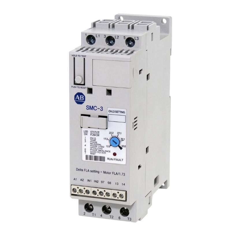
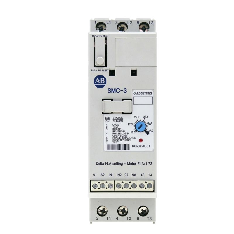
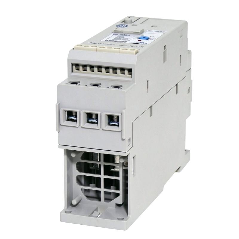
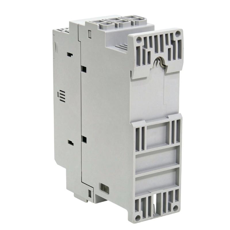
- Allen Bradley
- 150-C37NBR
- SMC-3 Smart Motor Controller
- USA
- 139.7 x 44.8 x 110 mm
- 0.86 kg
- Xiamen, China
- New & In Stock
- T/T, PayPal, Western Union
- 1 Year
- 1-3 Working Days
- DHL, UPS, TNT, FedEx and EMS.
- 24-Hour Service
- COO
- 3
Our advantage

Global Logistics
We have a 10-year logistics and express cooperation agreement, so our products can be shipped to any place in the world.

Brand new and original
Our products are imported in bulk from the place of origin. Because of the cooperative relationship, our products are all original and 100% new.

24-hour service
We provide 7*24 hours service to our customers. We will be there whenever you need us.

Price advantage
All our products are priced very favorably because we have our own warehouse and supply.
| Company Information | |||
| [email protected] | |||
| Mobile | +8615980777398 | ||
| +8615980777398 | |||
| 15980777398 |
Product Overview
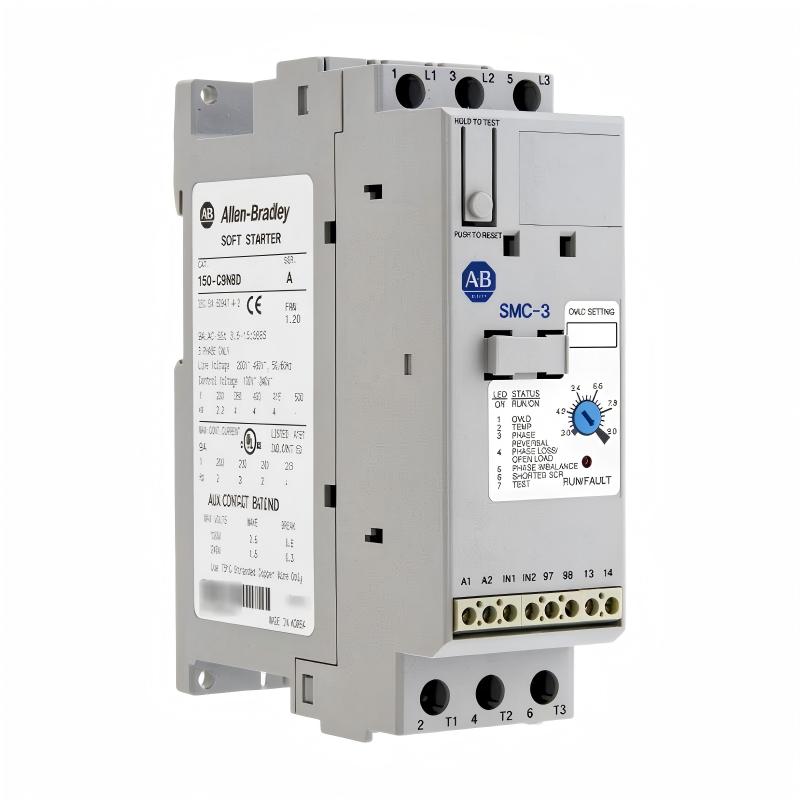
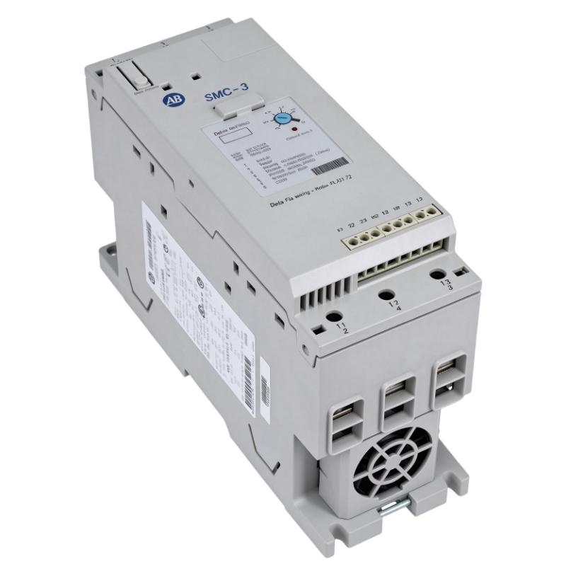
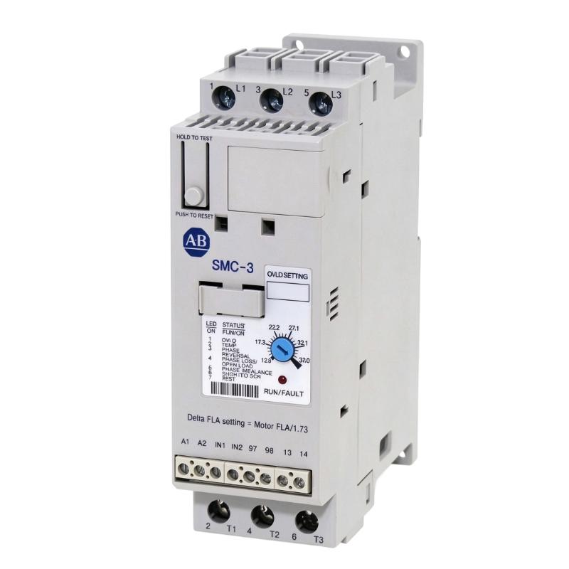
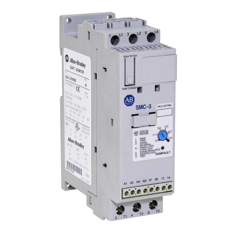
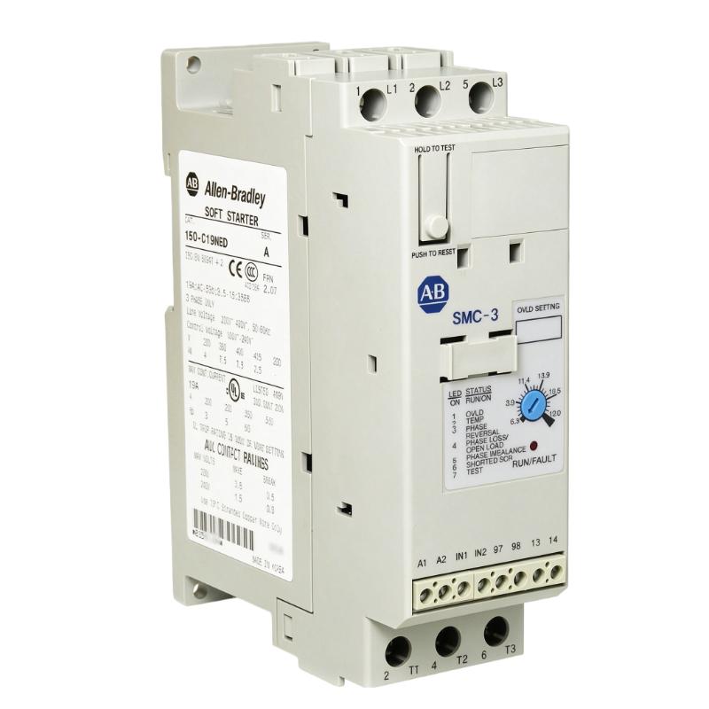
The Allen-Bradley 150-C37NBR SMC-3 Smart Motor Controller is a solid-state motor controller designed to provide controlled starting and stopping for three-phase AC induction motors. Part of the Bulletin 150 SMC-3 product family from Rockwell Automation, this controller combines soft-start functionality, motor overload protection, and integrated bypass operation in a compact industrial package.
Unlike a variable frequency drive, which continuously adjusts motor speed by changing output frequency, the SMC-3 primarily manages motor acceleration and stopping. It gradually increases the voltage applied to the motor during startup, helping reduce the high inrush current and mechanical shock commonly associated with direct-on-line starting.
The 150-C37NBR has a rated current of 37 A and is designed for three-phase power systems. It features a 24 V AC/DC control supply and an open-type enclosure for installation inside an appropriately designed electrical cabinet. Its three-wire control arrangement supports integration into industrial motor-control circuits.
The controller includes an internal bypass function and integrated motor overload protection. Additional operating functions include selectable current limits, adjustable starting times, selectable initial torque, kick-start settings, and soft-stop control. These features allow engineers to adapt motor starting and stopping behavior to different load conditions.
The 150-C37NBR is suitable for industrial applications where a motor needs controlled acceleration and stopping but does not require continuous variable-speed operation. Typical examples include pumps, fans, conveyors, compressors, and general-purpose machinery, provided the motor ratings and application requirements fall within the controller’s specified limits.
Technical Specifications
| Parameter | Specification |
|---|---|
| Brand | Allen-Bradley |
| Manufacturer | Rockwell Automation |
| Model | 150-C37NBR |
| Product Series | Bulletin 150 SMC-3 |
| Product Type | Smart Motor Controller / Soft Starter |
| Controller Configuration | Three-wire |
| Rated Current | 37 A |
| Supply Voltage Range | 200–460 V AC |
| Maximum Listed Voltage Class | 480 V AC |
| Power Supply Phase | Three-phase |
| Operating Frequency | 50/60 Hz |
| Control Voltage | 24 V AC/DC |
| Enclosure Type | Open type |
| Integrated Motor Overload Protection | Yes |
| Internal Bypass | Yes |
| Soft Stop | Yes |
| Selectable Current Limit | 150%, 250%, 350%, 450% |
| Selectable Trip Class | 10, 15, 20 |
| Selectable Start Time | 2–30 seconds |
| Selectable Initial Torque | 15%, 25%, 35%, 65% |
| Kick Start | Selectable, up to 1.5 seconds |
| Number of Power Poles | Three-phase |
| Protection Degree | IP2X |
| Dimensions | 139.7 × 44.8 × 110 mm |
| Weight | 0.86 kg |
| Typical Application | Three-phase AC motor starting and stopping |
Note: The 37 A rating is the controller’s rated current. The permitted motor current and power depend on supply voltage and whether the motor is connected in line or inside-delta. Always check the motor nameplate and the manufacturer’s selection tables before installation.
Function and Working Principle
The 150-C37NBR uses solid-state switching to manage the voltage applied to a motor during starting and stopping. Its primary purpose is to control motor acceleration and reduce the electrical and mechanical stresses associated with conventional direct starting.
1. Soft Starting
When a motor starts directly across the supply, it can draw a high initial current and produce a sudden torque increase. This may place additional stress on the electrical distribution system, motor windings, couplings, belts, and driven equipment.
The SMC-3 gradually increases the voltage supplied to the motor according to the selected starting parameters. This creates a controlled acceleration profile and helps reduce abrupt mechanical movement.
The starting time and initial torque can be adjusted to suit the motor and driven load.
2. Current-Limit Starting
The controller provides selectable current-limit settings of 150%, 250%, 350%, and 450% of the motor full-load current.
Current limiting is useful where the electrical supply has limited capacity or where reducing startup current is important. The selected value should provide enough starting torque to accelerate the load without exceeding the desired current level.
A setting that is too low may prevent the motor from accelerating properly. Engineers should therefore evaluate the motor’s starting characteristics and the driven equipment’s load requirements.
3. Soft Stopping
The soft-stop function gradually reduces motor voltage when a controlled stopping sequence is required.
This can be useful in applications where an abrupt stop may cause pressure changes, liquid movement, or mechanical shock. For example, some pump systems benefit from a controlled stopping profile to reduce sudden changes in fluid flow.
Soft stopping does not provide the same functionality as regenerative braking or precise speed control from a variable frequency drive. The stopping behavior must be assessed against the mechanical characteristics of the application.
4. Integrated Motor Overload Protection
The 150-C37NBR includes motor overload protection. The controller monitors operating conditions and can initiate a protective response when the motor experiences an overload condition according to the configured protection characteristics.
Selectable trip classes include Class 10, Class 15, and Class 20. These settings allow the protection response to be matched more closely to the motor’s starting and operating requirements.
Correct motor full-load current settings are essential. The overload function should be configured according to the motor nameplate and the applicable protection requirements.
5. Internal Bypass Operation
The integrated bypass function allows the controller to use its bypass arrangement after the motor has completed the starting process.
This reduces the time that the solid-state power components remain in the main current path during normal running. It can help reduce steady-state heat dissipation within the controller.
The bypass function is integrated into the controller, so a separate external bypass contactor is not necessarily required for the standard bypass operation. System design and isolation requirements must still follow the manufacturer’s instructions.
Role in Industrial Control Systems
The 150-C37NBR can be installed as part of an industrial motor-control panel and coordinated with PLCs, operator interfaces, protective devices, and other automation equipment.
PLC Integration
A programmable logic controller can manage the start and stop sequence of the motor through the controller’s control inputs. PLC logic may use process signals, interlocks, sensor feedback, or operating schedules to determine when the motor should run.
The 150-C37NBR uses a 24 V AC/DC control supply. Its control wiring should be designed according to the three-wire control arrangement and the manufacturer’s terminal information.
HMI and Operator Control
An HMI can provide operators with access to machine commands, operating status, and alarm information. In a typical arrangement, the HMI communicates with the PLC, while the PLC manages the soft starter.
This approach allows operators to start or stop equipment through a centralized interface and monitor related process conditions.
Motor Protection Coordination
The controller’s overload protection forms part of the motor protection strategy. However, it does not eliminate the need to coordinate upstream short-circuit protection, isolation equipment, grounding, and other protective devices.
Engineers should use the manufacturer’s short-circuit protection and coordination tables when selecting fuses or circuit breakers.
Motor Starting in Automated Production
The SMC-3 can support motor starting sequences in automated machinery. For example, a PLC may start a pump after a valve reaches the required position or start a conveyor after an upstream machine confirms readiness.
The soft starter manages the motor’s acceleration, while the PLC coordinates the wider process.
Industrial Applications
The 150-C37NBR is intended for three-phase AC motor starting applications. Its suitability depends on the motor’s rated current, supply voltage, starting torque, operating frequency, and duty cycle.
1. Pumping Systems
Pumps are common applications for soft starters because sudden motor acceleration and stopping can create pressure changes in pipework.
The SMC-3 can provide controlled motor acceleration and a selectable soft-stop function. These features may help reduce mechanical stress in suitable pumping installations.
The required starting torque and stopping profile should be evaluated according to the pump type and fluid system.
2. Industrial Fans and Blowers
Large fans and blowers can have significant rotating inertia. Direct starting may create high electrical demand and mechanical stress.
A soft starter can gradually accelerate the motor, allowing the fan to reach operating speed through a controlled starting process.
The 150-C37NBR may be considered when the motor’s current and voltage ratings are compatible with the controller.
3. Conveyor Systems
Conveyor equipment often benefits from controlled motor starting because sudden torque can cause belt movement, product displacement, or unnecessary mechanical stress.
The SMC-3 can provide a controlled acceleration profile for suitable conveyor motors. The selected starting time and initial torque should be matched to the belt load and mechanical design.
Where continuous speed adjustment is necessary, a variable frequency drive may be a more appropriate solution.
4. Air Compressors
Industrial compressors use electric motors to drive compression equipment. Depending on the compressor design and starting requirements, a soft starter can help manage motor acceleration and reduce the impact of starting current.
Before using the 150-C37NBR, engineers should check the compressor’s unloading arrangement, starting torque, restart frequency, and motor current.
5. General Manufacturing Machinery
The controller can be considered for compatible motors used in mixers, processing equipment, material-handling machinery, and other industrial installations.
Its selectable starting and overload settings provide flexibility for different motor and load conditions.
The application must be checked carefully to ensure that the soft starter provides sufficient starting torque and the required stopping behavior.
Installation and System Integration
Proper installation is essential for electrical safety, motor protection, and reliable operation.
1. Verify Motor and Supply Ratings
Before installing the 150-C37NBR, confirm the incoming supply voltage, phase configuration, and frequency. The controller is designed for three-phase motor applications and has a 37 A rated current.
The motor’s full-load current must fall within the controller’s permitted operating range. Selection also depends on the motor connection method.
For line-connected motors, the published current range is 12.3–37 A at 380/400/415/460 V AC. For delta-connected motors, the published range is 21–64 A at the listed voltage classes. These ranges are application-specific and should be checked against the manufacturer’s selection documentation.
2. Install Inside a Suitable Electrical Enclosure
The 150-C37NBR is an open-type controller with an IP2X protection rating. It is designed for installation inside a suitable electrical cabinet rather than direct exposure to an industrial environment.
The supplied dimensions are 139.7 × 44.8 × 110 mm. Allow sufficient room for power wiring, control wiring, cooling airflow, and maintenance access.
The enclosure should provide suitable protection against dust, moisture, and accidental contact according to the installation environment.
3. Connect the Control Supply
The controller uses a 24 V AC/DC control supply. Verify the supply polarity where applicable, voltage level, current capacity, and control wiring arrangement.
The start and stop circuit should follow the manufacturer’s three-wire control requirements. Incorrect control wiring can prevent normal operation or cause unexpected starting behavior.
4. Configure Starting Parameters
Select the starting time, initial torque, current limit, and other available parameters according to the motor and driven load.
For a pump, the starting profile may need to balance acceleration time and hydraulic requirements. For a conveyor, the settings should provide enough torque to move the load without creating excessive mechanical shock.
Avoid selecting parameters solely from general application examples. Actual motor and load characteristics should guide commissioning.
5. Configure Overload Protection
Set the motor overload parameters according to the motor nameplate and application requirements. Select the appropriate trip class based on the motor’s starting characteristics and expected acceleration time.
The overload setting must not exceed the motor’s permitted operating current simply to prevent nuisance trips. If the motor repeatedly trips, investigate the load, mechanical condition, supply quality, and starting configuration.
6. Coordinate Short-Circuit Protection
The SMC-3 must be used with suitable upstream short-circuit protective devices. Select fuses or circuit breakers according to the manufacturer’s coordination tables and the installation’s available fault current.
Do not assume that the controller’s overload protection provides short-circuit protection for the complete installation.
7. Commission the Motor
Before operating the system, inspect power and control wiring, grounding, protective devices, and mechanical connections.
Test the start and stop commands, motor rotation, acceleration, soft-stop behavior, overload response, and system interlocks. Record the final settings for future maintenance.
Compatible System Components
The 150-C37NBR is generally installed as part of a motor-control system with suitable electrical and automation components.
| Component | Function | Integration Considerations |
|---|---|---|
| Three-phase AC motor | Converts electrical energy into mechanical power | Verify motor current, voltage, connection method, and starting torque |
| PLC | Controls motor start and stop sequences | Confirm control input wiring and operating logic |
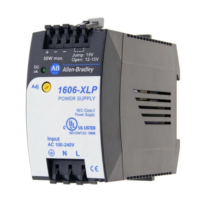
| 24 V AC/DC power supply | Supplies the controller’s control circuit | Match the specified control voltage and current requirements |
| HMI | Provides operator commands and equipment status | Usually communicates through the PLC |
| Circuit breaker or fuse | Provides short-circuit protection | Select according to the manufacturer’s coordination tables |
| Motor isolator | Provides electrical isolation for maintenance | Follow applicable safety and wiring requirements |
| Auxiliary contacts | Provide status and fault signals | Verify contact ratings and terminal assignments |
| Control cabinet | Houses the soft starter and associated equipment | Provide appropriate environmental protection and ventilation |
| Three-phase distribution system | Supplies power to the motor circuit | Confirm voltage, phase, frequency, and available fault current |
These are typical system components and are not necessarily included with the 150-C37NBR.
Alternative Models and Replacement Considerations
When replacing an existing SMC-3 controller, the complete catalog number and electrical configuration should be checked before selecting another model.
| Alternative Model | Description | Replacement Considerations |
|---|---|---|
| 150-C30NBR | SMC-3 Smart Motor Controller, 30 A | Lower current rating; verify motor current and duty |
| 150-C37NBD | SMC-3 Smart Motor Controller, 37 A | Similar current rating, but control-voltage configuration differs |
| 150-C43NBR | SMC-3 Smart Motor Controller, 43 A | Higher current rating; check mounting and application requirements |
| 150-C60NBR | SMC-3 Smart Motor Controller, 60 A | Higher current capacity; not a direct substitute without review |
| Allen-Bradley SMC Flex | Smart motor control family | May offer additional motor-control functions depending on the selected model |
| Allen-Bradley SMC-50 | Advanced smart motor controller family | Consider for applications requiring more advanced motor-control capabilities |
Before choosing a replacement, compare:
- Rated motor current and power.
- Supply voltage and frequency.
- Line-connected or inside-delta wiring.
- Control voltage and terminal arrangement.
- Three-wire or alternative control requirements.
- Overload protection settings and trip classes.
- Starting and stopping requirements.
- Internal bypass configuration.
- Short-circuit protection coordination.
- Mounting dimensions and cabinet clearances.
A replacement with the same rated current may still have different control wiring, functions, or protection requirements. Always verify the complete catalog number.
Key Advantages
Controlled Motor Starting
The SMC-3 gradually increases motor voltage during startup, helping reduce high inrush current and sudden mechanical torque.
Selectable Current Limit
Multiple current-limit settings allow engineers to adjust starting behavior according to the motor and power-system requirements.
Integrated Overload Protection
Built-in overload protection helps protect compatible motors against sustained overload conditions when correctly configured.
Internal Bypass
The integrated bypass function reduces the need for a separate external bypass arrangement in standard applications and helps limit steady-state heat dissipation.
Adjustable Soft Stop
The soft-stop function can reduce abrupt stopping behavior in applications where controlled deceleration is important.
Compact Open-Type Design
Its compact dimensions make the controller suitable for installation in appropriately designed industrial control cabinets.
24 V AC/DC Control Supply
The 24 V AC/DC control configuration supports integration into compatible industrial control circuits.
Technical FAQs
1. What is the Allen-Bradley 150-C37NBR?
The 150-C37NBR is an SMC-3 Smart Motor Controller from Allen-Bradley. It is a 37 A solid-state soft starter designed for controlled starting and stopping of three-phase AC motors.
2. Is the 150-C37NBR a variable frequency drive?
No. It is a soft starter, not a variable frequency drive. It controls motor acceleration and stopping but does not provide continuous variable-frequency speed regulation during normal operation.
3. What is the rated current?
The controller has a rated current of 37 A. The actual permitted motor current depends on the motor connection method, supply voltage, and application conditions.
4. What control voltage does it use?
The 150-C37NBR uses a 24 V AC/DC control supply. Verify the control circuit wiring and supply requirements before installation.
5. Does it have built-in overload protection?
Yes. The SMC-3 includes integrated motor overload protection with selectable trip classes of 10, 15, and 20.
6. Does the controller include an internal bypass?
Yes. The 150-C37NBR includes an internal bypass function that operates after the motor completes its starting process.
7. Can it be used with a PLC?
Yes. It can be incorporated into a PLC-based motor-control system. The PLC can coordinate the start and stop sequence through the controller’s compatible control inputs.
8. Can it control motor speed?
It controls the motor’s starting and stopping behavior, not continuous operating speed. If an application requires adjustable running speed, a suitable variable frequency drive should be considered.
9. What is the difference between 150-C37NBR and 150-C37NBD?
Both are 37 A SMC-3 controllers, but their control-supply configurations differ. The 150-C37NBR uses 24 V AC/DC control, while the 150-C37NBD uses a different control-voltage arrangement. Confirm the exact model before replacement.
10. What should be checked before purchasing?
Verify the complete catalog number, rated current, supply voltage, control voltage, enclosure condition, terminal condition, and product authenticity. For used or refurbished units, request clear photographs and functional test information.
Procurement and Maintenance Recommendations
When sourcing the Allen-Bradley 150-C37NBR, confirm that the catalog number matches the installed controller. Pay particular attention to the 37 A current rating, 24 V AC/DC control supply, three-wire configuration, and open-type enclosure.
For replacement projects, compare the motor nameplate current with the controller’s permitted operating range. Check whether the motor is line-connected or inside-delta, and verify that the selected controller supports the intended wiring arrangement.
For used or refurbished equipment, inspect the power terminals, control terminals, housing, and signs of overheating or physical damage. Request photographs of the nameplate and confirm whether the unit has been functionally tested.
During maintenance, inspect the cabinet environment, terminal tightness, grounding, protective devices, and motor wiring. Investigate repeated overload trips rather than simply increasing the overload setting. Mechanical binding, excessive load, poor ventilation, and incorrect starting parameters can all contribute to motor or controller problems.
Keep a record of the final configuration, including current-limit settings, starting time, initial torque, overload trip class, and control wiring. This information can simplify future troubleshooting and replacement work.
Conclusion
The Allen-Bradley 150-C37NBR SMC-3 Smart Motor Controller is a 37 A solid-state soft starter designed for three-phase AC motor applications. Its 24 V AC/DC control supply, integrated overload protection, internal bypass, selectable current limits, and adjustable starting and stopping functions make it suitable for a range of industrial motor-control systems.
For maintenance and replacement applications, the most important considerations are motor current, supply voltage, connection method, control voltage, and short-circuit protection coordination. Correct selection and commissioning help ensure that the controller operates reliably within the requirements of the connected motor and industrial process.