

ProductPRODUCT
Featured products
Contact Us
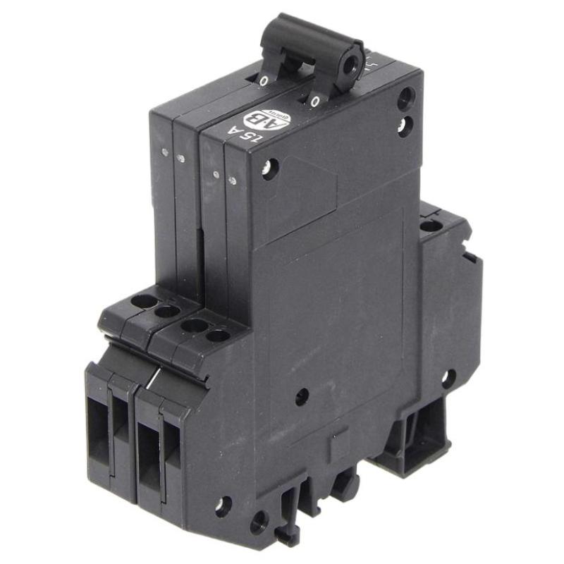
- Allen Bradley
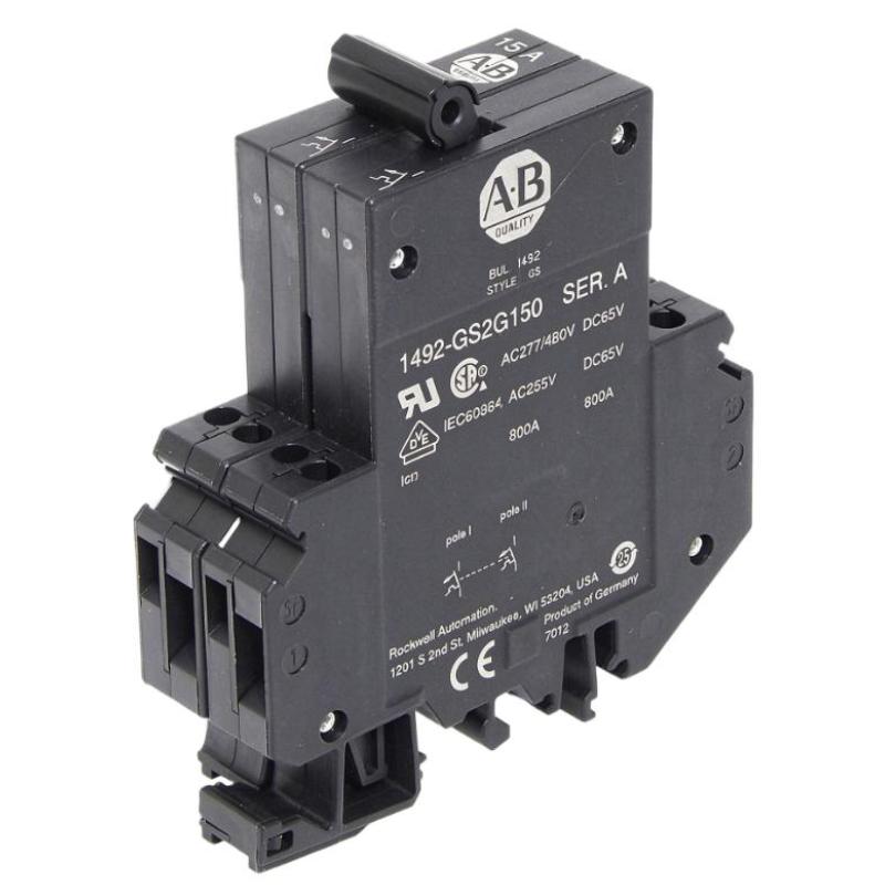
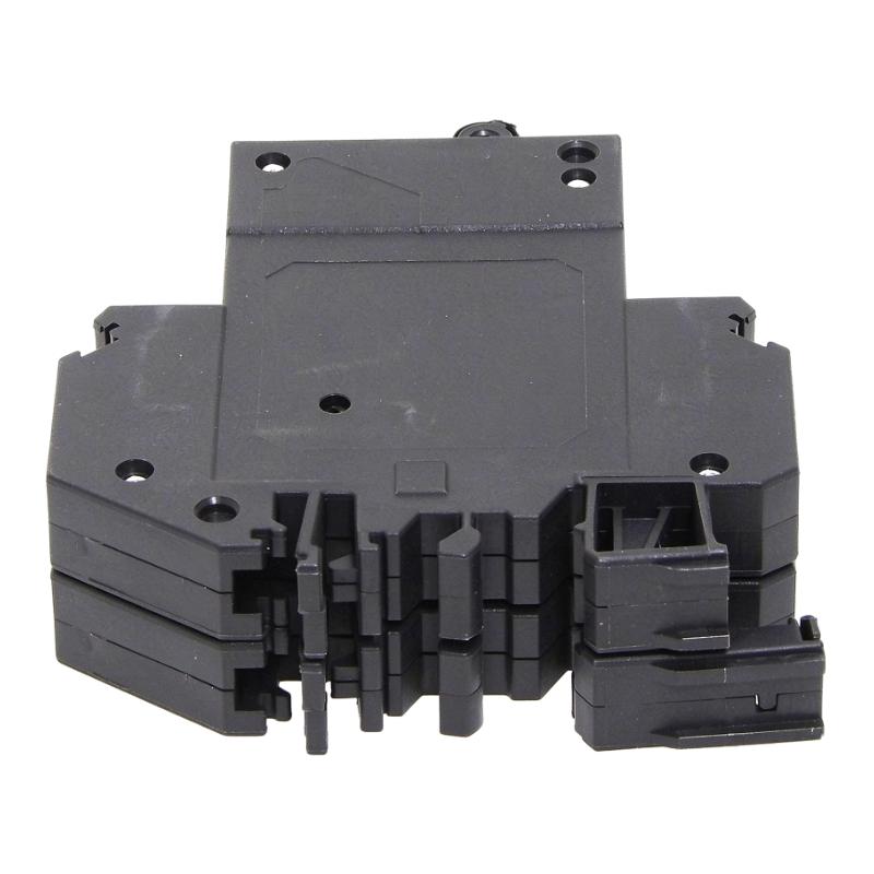
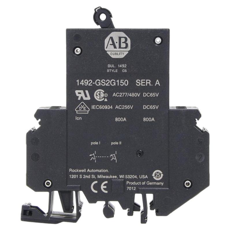
- 1492-GS2G150
- High-Density Miniature Circuit Breaker
- USA
- 95 x 35 x 80 mm
- 0.15 kg
- Xiamen, China
- New & In Stock
- T/T, PayPal, Western Union
- 1 Year
- 1-3 Working Days
- DHL, UPS, TNT, FedEx and EMS.
- 24-Hour Service
- COO
- 0
Our advantage

Global Logistics
We have a 10-year logistics and express cooperation agreement, so our products can be shipped to any place in the world.

Brand new and original
Our products are imported in bulk from the place of origin. Because of the cooperative relationship, our products are all original and 100% new.

24-hour service
We provide 7*24 hours service to our customers. We will be there whenever you need us.

Price advantage
All our products are priced very favorably because we have our own warehouse and supply.
| Company Information | |||
| [email protected] | |||
| Mobile | +8615980777398 | ||
| +8615980777398 | |||
| 15980777398 |
Product Overview
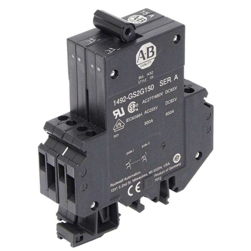
The Allen-Bradley 1492-GS2G150 High-Density Miniature Circuit Breaker is a compact supplementary circuit protection device manufactured by Rockwell Automation. Belonging to the Bulletin 1492-GS series, this model is designed to provide thermal-magnetic overcurrent protection for industrial control circuits and electrical equipment.
With a rated current of 15 A, a two-pole configuration, and G-trip characteristics, the 1492-GS2G150 is particularly suited to applications involving AC inductive loads. Its high-density design allows multiple protection devices to be installed within a limited control-panel space, making it useful in industrial automation cabinets, OEM machinery, and electrical distribution assemblies.
Circuit protection is an important part of industrial electrical system design. Motors, control transformers, power supplies, and auxiliary equipment can experience abnormal current conditions caused by overloads, wiring faults, or component failures. A correctly selected supplementary protector helps disconnect an affected circuit when its current exceeds the permitted operating range.
The 1492-GS2G150 uses a thermal-magnetic trip mechanism. Its thermal element responds to sustained overcurrent conditions, while its magnetic element responds to sufficiently high instantaneous current. The G-trip characteristic is intended for inductive AC loads, where normal startup current characteristics must be considered during protection-device selection.
The two-pole design provides simultaneous switching of two protected conductors. Its toggle-style operating mechanism allows manual operation and visual indication of the device’s operating position.
For industrial maintenance and replacement projects, the complete catalog number is important. Similar Bulletin 1492 devices may have different pole counts, current ratings, and trip characteristics. Selecting the correct configuration helps maintain the intended electrical protection and control-panel arrangement.
Technical Specifications
| Parameter | Specification |
|---|---|
| Brand | Allen-Bradley |
| Manufacturer | Rockwell Automation |
| Model | 1492-GS2G150 |
| Product Series | Bulletin 1492-GS |
| Product Type | High-Density Miniature Circuit Breaker |
| Protection Type | Supplementary Circuit Protection |
| Number of Poles | 2 |
| Rated Current | 15 A |
| Trip Technology | Thermal-Magnetic |
| Trip Characteristic | G-Trip |
| Intended Load Characteristic | AC Inductive Loads |
| Operating Frequency | 50/60 Hz |
| Operating Mechanism | Toggle Type |
| Auxiliary Contact | Not included in standard configuration |
| Mounting | Industrial control-panel mounting; verify rail and assembly requirements |
| Dimensions Provided | 95 × 35 × 80 mm |
| Weight Provided | 0.15 kg |
| Lifecycle Status | Active |
Note: Dimensions and weight are the supplied listing values. The manufacturer’s published product information specifies an 80 mm height and 88.5 mm depth. Confirm the complete mechanical drawing before finalizing panel dimensions.
Function and Working Principle
The primary function of the 1492-GS2G150 is to provide supplementary overcurrent protection for electrical circuits. It monitors the current flowing through its protected poles and interrupts the circuit when an abnormal current condition activates its trip mechanism.
1. Thermal Protection
The thermal protection element responds to sustained overcurrent conditions.
When current remains above the permitted level, heat builds up within the thermal element. Once the temperature reaches the designed operating threshold, the mechanism releases the contacts and disconnects the protected circuit.
This function helps protect wiring and connected equipment against prolonged overload conditions.
2. Magnetic Protection
The magnetic protection element responds to high current conditions that occur over a short period.
For example, an electrical fault may produce a sudden current increase. The magnetic trip mechanism reacts rapidly when the current reaches the specified operating region.
This fast response helps limit the duration of abnormal current flow and reduces the risk of damage to connected components.
3. G-Trip Characteristics
The 1492-GS2G150 uses G-trip characteristics intended for AC inductive loads.
Inductive equipment can draw higher current during startup than during normal operation. The trip characteristic must therefore be matched to the expected inrush current and the electrical characteristics of the connected load.
Correct selection helps balance reliable startup operation with the need for effective overcurrent protection.
4. Two-Pole Circuit Interruption
The two-pole construction allows both protected conductors to be disconnected through the common operating mechanism.
This arrangement is useful in control-panel circuits where two conductors require coordinated switching. The exact system voltage and conductor arrangement must be checked against the manufacturer’s electrical ratings.
5. Manual Toggle Operation
The toggle mechanism provides a convenient way to operate the device manually.
Maintenance personnel can use the handle to switch the protected circuit on or off. The handle position also provides a basic indication of the device’s operating state.
Manual operation does not replace safe electrical isolation procedures. Appropriate lockout and verification practices remain necessary before servicing connected equipment.
Role in Industrial Control Systems
The 1492-GS2G150 can be installed in industrial control panels to protect selected electrical circuits and auxiliary equipment.
Control Circuit Protection
Industrial control cabinets contain many electrical circuits, including PLC power supplies, relay circuits, sensors, actuators, and interface equipment.
A supplementary protector can help isolate an affected circuit without necessarily interrupting unrelated sections of the control system. This supports easier fault investigation and maintenance.
Power Supply Protection
Control power supplies provide low-voltage DC power for automation devices and control components. Their input circuits may require appropriately selected supplementary protection.
The 1492-GS2G150 can be considered for a suitable circuit when the current rating, voltage rating, and fault-current requirements match the installation.
Motor and Inductive Load Circuits
Inductive loads can produce startup current characteristics that differ from resistive loads. The G-trip characteristic is intended for this type of AC load behavior.
Engineers should still verify the actual load current, inrush characteristics, conductor ratings, and upstream protection before using this model in a particular motor-related circuit.
Electrical Distribution Coordination
The breaker may form part of a larger protection arrangement containing upstream circuit breakers, fuses, contactors, and distribution terminals.
Protection coordination should be evaluated as a complete system. A supplementary protector should not automatically be treated as a replacement for the required branch-circuit protection.
Industrial Applications
The 1492-GS2G150 is suitable for selected industrial control and auxiliary electrical circuits where its two-pole, 15 A rating and G-trip characteristics match the application.
1. Industrial Control Panels
Control panels contain multiple circuits that supply automation controllers, relays, power supplies, and other electrical components.
High-density supplementary protectors help organize circuit protection within compact enclosures. The 1492-GS2G150 can be used where a two-pole, 15 A protection arrangement is appropriate.
2. AC Inductive Loads
The G-trip characteristic makes this model relevant to suitable AC inductive loads.
Examples may include auxiliary transformers, control equipment, and other inductive devices whose startup characteristics are compatible with the specified trip behavior.
The actual electrical ratings must always be checked before installation.
3. PLC and Automation Equipment
Programmable logic controller systems often include separate power and auxiliary circuits.
A supplementary protector can help isolate selected circuits during abnormal current conditions, supporting maintenance and fault diagnosis.
The breaker should be selected according to the connected equipment’s current requirements and the system’s protection design.
4. OEM Machinery
Original equipment manufacturers often need compact circuit protection devices that fit into standardized control cabinets.
The high-density design of the 1492-GS series supports space-conscious panel layouts. The 1492-GS2G150 can be considered for suitable machine-control circuits where a 15 A, two-pole device is required.
5. Industrial Auxiliary Equipment
Auxiliary equipment may include small electrical assemblies, control transformers, and other supporting devices.
The breaker can provide supplementary protection when the connected circuit’s electrical characteristics are within the device’s specified ratings.
6. Electrical Distribution Assemblies
The device may be installed in suitable electrical distribution and control assemblies where coordinated two-pole protection is required.
Engineers should evaluate short-circuit current, upstream protection, conductor capacity, and the applicable installation standards before approving its use.
Installation and System Integration
Correct installation is essential for reliable protection and safe operation.
1. Verify Electrical Ratings
Before installation, confirm the system voltage, frequency, load current, and required pole configuration.
The 1492-GS2G150 is a 15 A, two-pole model. Its suitability depends on the actual electrical system and the applicable manufacturer ratings.
Do not select a breaker based only on the normal operating current. Startup current, fault-current availability, and conductor ampacity must also be considered.
2. Confirm Mounting Requirements
Check the mounting arrangement and control-panel assembly requirements before installation.
The supplied dimensions are 95 × 35 × 80 mm. Verify these measurements against the manufacturer’s mechanical drawing, particularly where several devices are installed side by side.
Allow sufficient room for terminal wiring, handle operation, inspection, and maintenance access.
3. Connect Conductors Correctly
Use conductors within the permitted wire range and follow the manufacturer’s terminal torque specifications.
Ensure that conductors are properly stripped and secured. Loose terminals can cause overheating, intermittent operation, and equipment damage.
Do not exceed the terminal’s permitted conductor capacity or tightening torque.
4. Coordinate Upstream Protection
The 1492-GS2G150 is a supplementary protector. The complete installation may require upstream branch-circuit protection.
Engineers should evaluate the available short-circuit current and the interrupting ratings applicable to the installation. The protective arrangement must comply with the relevant electrical codes and manufacturer instructions.
5. Test Circuit Operation
After installation, inspect the connections and verify that the device is correctly installed in the intended circuit.
Check the operating handle and confirm that connected equipment receives power as expected. Any functional testing should follow the manufacturer’s procedures and be performed by qualified personnel.
6. Maintain Safe Working Conditions
Before maintenance, isolate the circuit and verify the absence of hazardous voltage.
Do not rely solely on the breaker handle as proof that equipment is electrically safe. Follow the facility’s lockout/tagout procedures and applicable electrical safety requirements.
Compatible System Components
The 1492-GS2G150 can be used alongside other electrical and automation components in a properly engineered control panel.
| Component | Function | Integration Considerations |
|---|---|---|
| PLC power supply | Provides control power to PLC equipment | Verify input current and protection requirements |
| Control transformer | Supplies the required control voltage | Confirm primary-side circuit ratings |
| Industrial relays | Switch control and auxiliary circuits | Match circuit current and voltage ratings |
| Contactors | Control electrical loads | Coordinate with upstream and downstream protection |
| Terminal blocks | Provide organized wiring connections | Confirm conductor size and terminal capacity |
| DIN rail or mounting assembly | Supports panel-mounted equipment | Verify mechanical compatibility |
| Distribution terminals | Distribute electrical power | Check current capacity and conductor arrangement |
| Control cabinet | Houses protection and automation equipment | Provide suitable space and environmental protection |
| Upstream circuit breaker | Provides branch-circuit protection | Coordinate protection ratings and interrupting capacity |
These components are examples of equipment that may be used in the same installation. They are not necessarily included with the 1492-GS2G150.
Alternative Models and Replacement Considerations
The Bulletin 1492-GS series includes several configurations with different current ratings and pole counts.
| Model or Series | Configuration | Replacement Considerations |
|---|---|---|
| 1492-GS1G150 | 1-pole, 15 A | Different pole configuration; not a direct substitute for a two-pole requirement |
| 1492-GS2G150 | 2-pole, 15 A | Original specified configuration |
| 1492-GS3G150 | 3-pole, 15 A | Three-pole configuration for applications requiring three protected poles |
| 1492-GS2G100 | 2-pole, 10 A | Lower current rating; requires circuit and load reassessment |
| 1492-GS2G200 | 2-pole, 20 A | Higher current rating; conductor and equipment protection must be reassessed |
| 1492-GS2G250 | 2-pole, 25 A | Different current rating and application requirements |
Before selecting an alternative, verify:
- Number of poles.
- Rated current.
- Operating voltage.
- AC or DC application requirements.
- G-trip characteristics.
- Thermal-magnetic protection behavior.
- Short-circuit and interrupting ratings.
- Mounting arrangement and dimensions.
- Terminal configuration and conductor requirements.
- Applicable approvals and installation standards.
A breaker with a higher current rating should not be selected simply because it fits the same mounting arrangement. The replacement must provide suitable protection for the connected conductors and equipment.
Key Advantages
High-Density Design
The Bulletin 1492-GS family is designed for compact industrial panel layouts. Its high-density format can help organize multiple protection devices in limited enclosure space.
15 A Current Rating
The 15 A rating provides a defined protection option for circuits whose electrical requirements match the device specification.
Two-Pole Configuration
The two-pole design allows coordinated switching of two protected conductors, making it suitable for selected industrial circuit arrangements.
Thermal-Magnetic Protection
The combined thermal and magnetic mechanism responds to sustained overload and high-current fault conditions.
G-Trip Characteristics
The G-trip characteristic is intended for AC inductive loads, helping accommodate their specific operating and startup current behavior when correctly selected.
Toggle-Style Operation
The manual toggle mechanism provides convenient switching and a visible handle position.
Industrial Automation Compatibility
The device can be incorporated into suitable control cabinets containing PLCs, relays, power supplies, contactors, and other automation components.
Technical FAQs
1. What is the Allen-Bradley 1492-GS2G150?
It is a high-density supplementary circuit breaker from the Allen-Bradley Bulletin 1492-GS series. It provides thermal-magnetic protection and is designed for selected industrial AC circuits.
2. What is the rated current?
The rated current is 15 A.
3. How many poles does this model have?
The 1492-GS2G150 is a two-pole circuit breaker.
4. What does G-trip mean?
G-trip refers to the trip characteristic specified for this model. It is intended for AC inductive loads and accounts for their particular current behavior.
5. What protection mechanism does it use?
It uses thermal-magnetic protection. The thermal element responds to sustained overload, while the magnetic element responds to sufficiently high instantaneous current.
6. Can it be used in PLC control panels?
Yes. It can be installed in a suitable industrial control panel to provide supplementary protection for selected electrical circuits. Its ratings must match the connected equipment and circuit design.
7. Is it suitable for motor protection?
It may be used in suitable AC inductive-load circuits, but it should not automatically be considered a complete motor-protection solution. Motor protection and branch-circuit requirements must be evaluated separately.
8. Does it include an auxiliary contact?
The standard 1492-GS2G150 configuration does not include an auxiliary contact. The 1492-GS family has configurations that can be ordered with an optional normally open auxiliary contact. Confirm the complete catalog number when ordering.
9. What should be checked before replacing an existing unit?
Check the pole count, rated current, voltage, G-trip characteristic, mounting arrangement, terminal configuration, and required protection ratings. Confirm the complete catalog number before installation.
10. What maintenance does this circuit breaker require?
Maintenance should include visual inspection, checking terminal condition, verifying mounting security, and looking for signs of overheating or physical damage. Electrical testing and replacement should follow the manufacturer’s instructions and be performed by qualified personnel.
Procurement and Maintenance Recommendations
When purchasing the Allen-Bradley 1492-GS2G150, verify the complete catalog number and confirm that the device is the two-pole, 15 A G-trip version.
For replacement projects, compare the original unit’s pole count, current rating, trip characteristic, voltage requirements, terminal arrangement, and mounting dimensions. A similar-looking miniature circuit breaker may have a different protection characteristic and may not be suitable for the same circuit.
For used or surplus equipment, request clear photographs of the front label, terminals, and overall condition. Check for damaged handles, cracked housings, discolored terminals, corrosion, or evidence of overheating. Confirm whether the unit is new, unused surplus, or refurbished.
During maintenance, inspect the connected conductors and terminals for loose connections or heat damage. Investigate the cause of repeated trips instead of repeatedly resetting the breaker. Frequent tripping may indicate an overload, wiring fault, unsuitable device selection, or abnormal load condition.
The breaker should always be installed as part of a coordinated protection arrangement. Correct conductor sizing, upstream protection, and fault-current evaluation are essential for a safe and reliable industrial electrical system.
Conclusion
The Allen-Bradley 1492-GS2G150 High-Density Miniature Circuit Breaker is a two-pole, 15 A supplementary protector designed for industrial electrical and automation applications. Its thermal-magnetic mechanism and G-trip characteristics make it suitable for selected AC inductive-load circuits.
With its compact high-density design and toggle-style operating mechanism, the device can be incorporated into industrial control panels, auxiliary electrical circuits, and OEM machinery. Accurate verification of current rating, pole configuration, voltage, and protection coordination is essential when selecting or replacing this circuit breaker.