
NewsNEWCENTER
Featured products

Contact Us
Allen-Bradley 1440-TB-E Screw Clamp Terminal Base Installation Guide
2026-07-07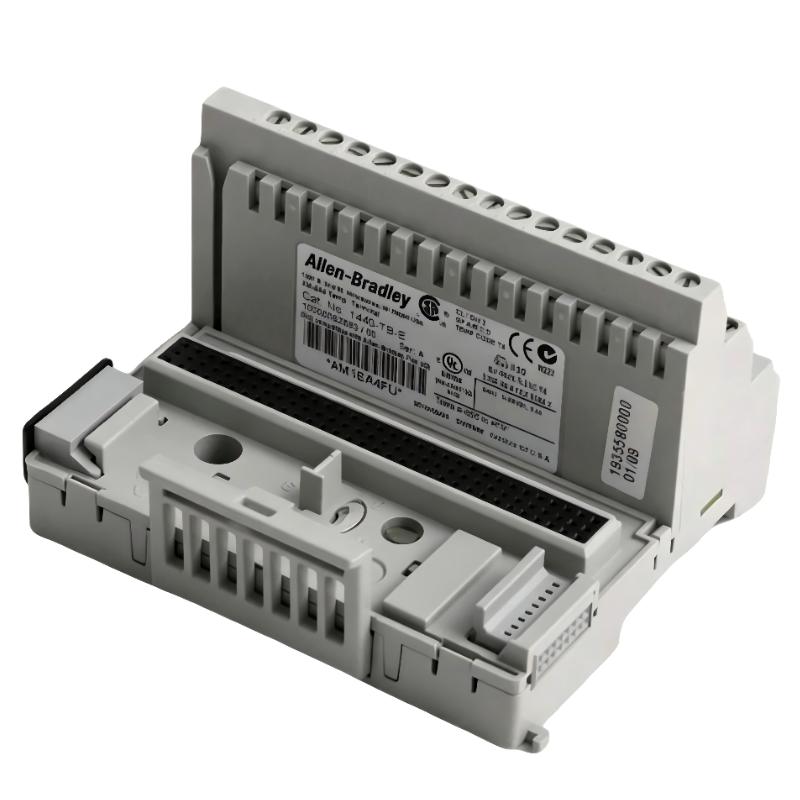
Table of Contents
- Installation Overview of 1440-TB-E Terminal Base
- Application Role in XM Condition Monitoring System
- Pre-Installation Inspection & Cabinet Preparation
- DIN Rail Installation & Mechanical Fixing
- Screw Clamp Wiring & Sensor Signal Connection
- Signal Shielding & Grounding Configuration
- Commissioning & Signal Verification Procedure
- FAQs on 1440-TB-E Installation
- Engineering Summary & Field Experience
Installation Overview of 1440-TB-E Terminal Base
The Allen-Bradley 1440-TB-E screw clamp terminal base is an interface component used with XM series condition monitoring equipment. It provides organized field wiring termination for measurement signals such as vibration, speed, and dynamic monitoring inputs.
In industrial applications, correct terminal base installation is essential because unstable connections can affect signal quality, create false alarms, and reduce the reliability of the complete condition monitoring system.
Application Role in XM Condition Monitoring System
The 1440-TB-E terminal base works as the connection point between field sensors and XM monitoring modules. It provides:
- Secure screw clamp electrical connection
- Structured sensor cable management
- Stable signal routing inside control cabinets
- Improved maintenance accessibility during troubleshooting
For vibration monitoring applications, even small contact resistance changes can influence low-level analog measurement signals.
Pre-Installation Inspection & Cabinet Preparation
- Confirm 1440-TB-E compatibility with the selected XM module
- Inspect terminal screws and clamp mechanisms before installation
- Prepare correct wire labels according to system drawings
- Check cabinet grounding condition
- Keep sensor wiring separated from high-current cables
During one field installation, engineers found that incorrect cable routing near a motor drive cabinet introduced unstable vibration readings before the XM system was even commissioned.
DIN Rail Installation & Mechanical Fixing
- Position the terminal base correctly on the DIN rail
- Engage the locking mechanism completely
- Verify mechanical stability after mounting
- Check alignment with adjacent XM system components
A secure mechanical connection prevents movement-related contact problems in industrial environments with continuous vibration.
Screw Clamp Wiring & Sensor Signal Connection
Correct termination is one of the most important steps during the 1440-TB-E Installation Guide process.
- Use appropriate wire size according to application requirements
- Install ferrules on stranded conductors when required
- Maintain consistent wire stripping length
- Tighten terminal screws evenly
- Verify each channel according to wiring documentation
TB_E_SETUP /MODEL=1440-TB-E /WIRE_CHECK /CHANNEL_VERIFY /CONTACT_TEST
Signal Shielding & Grounding Configuration
- Use shielded cable for sensitive measurement signals
- Apply single-point shield grounding practice
- Avoid creating ground loops between cabinets
- Separate analog signal grounding from power wiring
In one commissioning case, correcting the shield connection reduced unstable signal fluctuations and improved vibration trend consistency.
Commissioning & Signal Verification Procedure
- Perform wiring continuity verification
- Confirm terminal identification and channel mapping
- Check sensor signal response through XM configuration software
- Monitor signal stability during machine startup
- Record baseline operating data for future troubleshooting
FAQs on 1440-TB-E Installation
Why does the terminal base affect XM system accuracy?
Because unstable electrical contact can introduce signal variation before the measurement reaches the XM module.
Can loose screw connections create false alarms?
Yes. Intermittent resistance changes can produce unstable signals that may appear as equipment condition changes.
What should be checked before commissioning?
Wire termination, grounding, channel mapping, and signal continuity should all be verified before system startup.
Engineering Summary & Field Experience
The Allen-Bradley 1440-TB-E screw clamp terminal base is a critical connection point in XM condition monitoring systems. Reliable operation depends on proper mechanical installation, accurate wiring, correct shielding, and careful commissioning. Field experience shows that many monitoring issues originate from termination quality rather than electronic module failure.