
NewsNEWCENTER
Featured products

Contact Us
Allen-Bradley 1440-TB-E Screw Clamp Terminal Base Fault Troubleshooting Guide
2026-07-07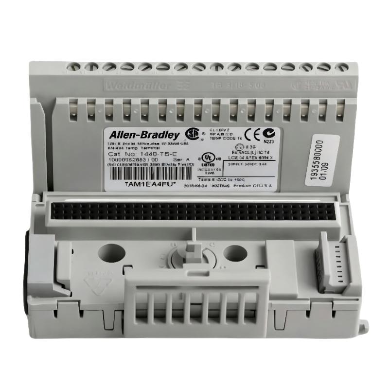
Table of Contents
- Field Case: XM Channel Instability Caused by Terminal Connection Fault
- 1440-TB-E Terminal Base Fault Symptoms
- Fault Thinking Process for Signal Abnormalities
- Common Causes of 1440-TB-E Signal Problems
- 1440-TB-E Fault Diagnosis Procedure
- Terminal Base Repair and Recovery Actions
- Post-Repair Testing and System Validation
- FAQs on 1440-TB-E Troubleshooting
- Engineering Summary
Field Case: XM Channel Instability Caused by Terminal Connection Fault
The Allen-Bradley 1440-TB-E screw clamp terminal base troubleshooting process usually begins with signal behavior analysis rather than immediate hardware replacement. In one machinery monitoring project, engineers received repeated vibration alarms from an XM system even though the rotating equipment showed normal operating conditions.
Initial inspection focused on the sensor and XM module, but the actual fault was traced to an unstable terminal connection inside the 1440-TB-E interface.
1440-TB-E Terminal Base Fault Symptoms
Typical field symptoms of a 1440-TB-E fault include:
- Intermittent vibration signal disappearance
- Unexpected channel fluctuation during stable operation
- Random high-frequency noise appearing in trends
- False equipment alarms without mechanical evidence
- Signal recovery after cabinet inspection or cable movement
Fault Thinking Process for Signal Abnormalities
Experienced engineers usually avoid replacing modules immediately. The troubleshooting logic follows the signal path:
- Verify sensor output condition
- Check cable continuity from field device to cabinet
- Inspect terminal base contact quality
- Confirm XM module input behavior
- Compare abnormal channel with healthy channels
In the actual case, the sensor output remained within normal range, but the signal became unstable after passing through the terminal connection point.
Common Causes of 1440-TB-E Signal Problems
The most common causes of Allen-Bradley 1440-TB-E terminal base faults include:
- Loose screw clamp connections
- Incorrect wire stripping length
- Damaged conductor strands
- Oxidation on contact surfaces
- Poor shield termination
- Electrical noise from nearby power equipment
Unlike active electronic modules, terminal bases usually fail through mechanical connection degradation rather than internal electronic damage.
1440-TB-E Fault Diagnosis Procedure
A practical troubleshooting sequence can include:
- Record abnormal channel behavior from XM monitoring software
- Compare signal trend with another stable channel
- Perform continuity measurement across terminal points
- Check screw clamp tightness and conductor condition
- Inspect grounding and shield connection
TB_E_FAULT_DIAG /MODEL=1440-TB-E /SIGNAL_CHECK /CONTINUITY_TEST /SHIELD_VERIFY
During one troubleshooting activity, engineers measured a vibration signal dropping from a stable 2.4 mm/s RMS to unstable values below 0.5 mm/s. After correcting the terminal connection, the reading returned to normal operation.
Terminal Base Repair and Recovery Actions
- Removed and inspected affected conductors
- Replaced damaged wire ends
- Installed proper ferrule termination
- Retightened screw clamp connections
- Corrected shield grounding arrangement
After repair, the XM system recovered stable signal transmission without replacing the monitoring module.
Post-Repair Testing and System Validation
- Monitor vibration trends during machine startup
- Confirm no repeated communication or signal alarms
- Verify channel stability under operating vibration
- Save updated baseline measurement data
A successful repair should restore stable measurement performance, not only eliminate temporary alarms.
FAQs on 1440-TB-E Troubleshooting
Can the 1440-TB-E terminal base cause false vibration alarms?
Yes. Poor electrical contact can introduce unstable signals that appear similar to real machine vibration changes.
Should the XM module be replaced first when a signal fails?
No. Engineers should check wiring paths and terminal connections before replacing expensive electronic components.
How can terminal faults be prevented?
Regular inspection, correct torque control, proper wire termination, and good grounding practices reduce failure risk.
Engineering Summary
The Allen-Bradley 1440-TB-E screw clamp terminal base plays an important role in XM condition monitoring signal reliability. Effective Troubleshooting and Fault Diagnosis require a complete understanding of the signal path, from field sensor to monitoring module. Field experience shows that loose connections, shielding problems, and wiring defects are the most common causes of unstable measurements.