
NewsNEWCENTER
Featured products

Contact Us
Allen-Bradley 1440-TB-B Terminal Base Installation Guide
2026-07-02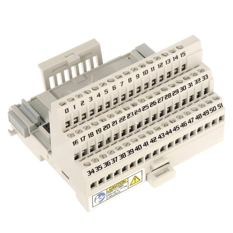
Table of Contents
- Installation Overview of 1440-TB-B Terminal Base
- Role in XM Condition Monitoring System Architecture
- Pre-Installation Inspection & Layout Planning
- DIN Rail Mounting & Mechanical Stability
- Screw Clamp Wiring & Signal Termination Rules
- Grounding & Shielding Strategy
- Commissioning & Channel Continuity Test
- FAQs on 1440-TB-B Installation
- Engineering Summary & Field Practice
Installation Overview of 1440-TB-B Terminal Base
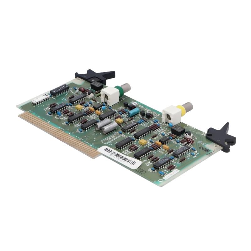
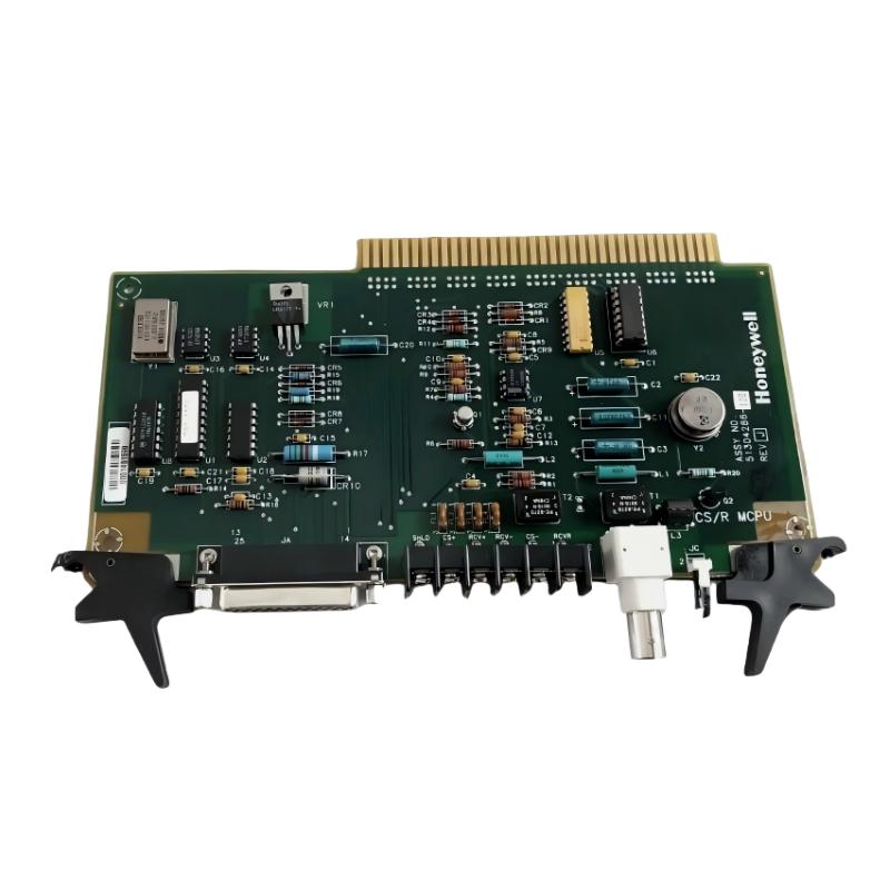
The Allen-Bradley 1440-TB-B terminal base is a screw-clamp termination platform designed for XM series condition monitoring modules. It provides secure electrical connection points for vibration, speed, and dynamic measurement signals in industrial machinery protection systems.
Compared with general terminal blocks, the 1440-TB-B is optimized for low-level analog signals requiring high noise immunity and stable grounding architecture.
Role in XM Condition Monitoring System Architecture
The 1440-TB-B serves as the interface layer between field sensors and XM modules. It ensures organized wiring distribution, stable signal referencing, and proper shielding continuity in condition monitoring cabinets.
Pre-Installation Inspection & Layout Planning
- Verify compatibility with XM series module footprint
- Inspect screw clamp integrity and insulation condition
- Plan channel grouping according to sensor type
- Ensure sufficient space for cable bending radius
- Confirm cabinet grounding layout before installation
DIN Rail Mounting & Mechanical Stability
- Align 1440-TB-B onto standard DIN rail
- Press firmly until locking mechanism engages
- Check for vibration resistance and no lateral movement
- Group terminal bases to match XM module channel layout
Field experience shows that improper DIN rail engagement can cause intermittent signal instability under high vibration environments.
Screw Clamp Wiring & Signal Termination Rules
- Use ferrules for all stranded conductors
- Tighten screw clamps to specified torque level
- Avoid over-tightening that may damage conductor strands
- Maintain consistent wire labeling for channel traceability
TB_B_CHECK /MODEL=1440-TB-B /CONTINUITY_VERIFY /TERMINATION_TEST /CLAMP_TORQUE_VALIDATION
Loose termination is one of the most common causes of intermittent vibration signal noise in XM systems using 1440-TB-B bases.
Grounding & Shielding Strategy
- Implement single-point grounding for all signal shields
- Avoid multiple ground references in cabinet wiring
- Separate analog signal grounding from power grounding paths
- Ensure low impedance earth connection for cabinet chassis
In one field case, correcting a ground loop reduced signal noise by over 50% and stabilized vibration trends significantly.
Commissioning & Channel Continuity Test
- Perform continuity test for each channel before startup
- Verify sensor response through XM module interface
- Check signal stability under operational vibration conditions
- Confirm correct channel mapping in configuration software
FAQs on 1440-TB-B Installation
Is 1440-TB-B interchangeable with other TB series bases?
No. It must match XM module compatibility to ensure correct electrical and mechanical interface.
Can poor tightening affect measurement accuracy?
Yes. Poor screw clamp torque introduces resistance variation and signal instability.
Why is shielding so critical?
Because XM systems process low-level analog signals highly sensitive to EMI interference.
Engineering Summary & Field Practice
The Allen-Bradley 1440-TB-B terminal base is a critical interface component in XM condition monitoring systems. Proper installation depends on correct DIN rail mounting, reliable screw clamp torque, and disciplined grounding strategy. Field experience confirms that most signal issues originate from termination and wiring practices rather than module failure.