
NewsNEWCENTER
Featured products
Contact Us
Allen-Bradley 1440-SDM02-01RA XM-124 Standard Dynamic Measurement Module Installation Guide
2026-06-29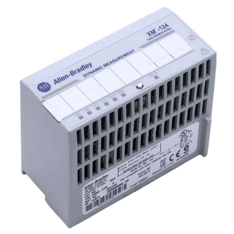
Table of Contents
- Installation Overview of XM-124 Dynamic Measurement Module
- Role in Condition Monitoring System Architecture
- Pre-Installation Electrical & Sensor Checks
- DIN Rail Mounting & Hardware Layout
- Sensor Wiring: Accelerometer, Proximity Probe & Tach Input
- Module Configuration & Channel Setup
- Commissioning & Vibration Baseline Setup
- FAQs on XM-124 Installation
- Engineering Summary & Field Practice
Installation Overview of XM-124 Dynamic Measurement Module
The Allen-Bradley 1440-SDM02-01RA XM-124 Standard Dynamic Measurement Module is a two-channel condition monitoring device used for vibration, pressure, strain, and dynamic signal analysis in rotating machinery. It also supports tachometer input for speed-based diagnostics.
XM-124 modules are widely used in turbine, compressor, pump, and motor protection systems where real-time vibration analysis is required.
Role in Condition Monitoring System Architecture
The XM-124 acts as a signal acquisition and processing node in industrial condition monitoring systems. It collects analog signals from vibration sensors and converts them into diagnostic parameters such as RMS, peak, FFT bands, and speed-related vibration trends.
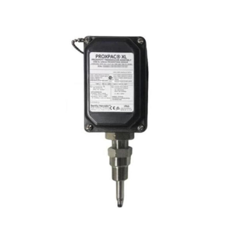
Pre-Installation Electrical & Sensor Checks
- Verify 24V DC power supply stability (Class 2 / SELV recommended)
- Check sensor type compatibility (IEPE accelerometers, proximity probes)
- Confirm cable shielding integrity for vibration signals
- Ensure correct grounding strategy for measurement accuracy
- Validate tachometer signal level and pulse quality
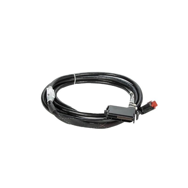
DIN Rail Mounting & Hardware Layout
- Mount XM-124 securely on DIN rail inside control cabinet
- Maintain separation from high-voltage switching devices
- Ensure airflow clearance for thermal stability
- Avoid routing sensor cables alongside VFD output cables
Field practice shows that improper cable routing near VFDs introduces high-frequency noise, affecting vibration signal accuracy.
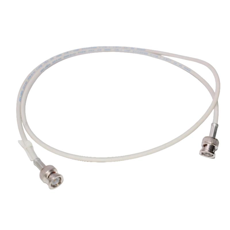
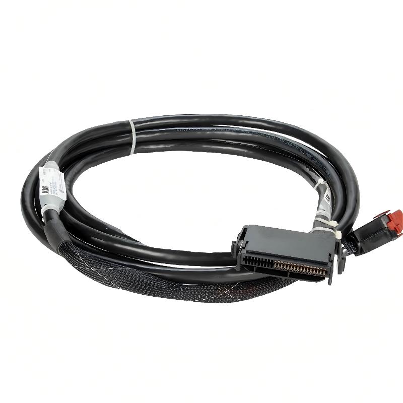
Sensor Wiring: Accelerometer, Proximity Probe & Tach Input
- Channel 1–2: connect vibration sensors (accelerometers or proximity probes)
- Tach input: connect speed sensor for synchronous analysis
- Use shielded twisted-pair cables for all analog inputs
- Ground shield at single point only (control cabinet side)
XM124_WIRING_CHECK /MODEL=1440-SDM02-01RA /CHANNEL_VERIFY /TACH_SETUP /NOISE_TEST
Module Configuration & Channel Setup
- Configure input type: voltage / IEPE / proximity probe
- Set scaling parameters for vibration units (mm/s, g, μm)
- Enable synchronous or asynchronous measurement mode
- Configure alarm thresholds (Alert / Danger levels)
XM-124 supports advanced signal processing including RMS, peak, and FFT-based diagnostics for rotating equipment health assessment.
Commissioning & Vibration Baseline Setup
- Start machine under no-load condition first
- Record baseline vibration signature at stable speed
- Verify tach signal synchronization with vibration channels
- Check noise floor and signal stability
- Confirm alarm logic activation under controlled conditions
In one commissioning case, incorrect tach scaling caused false “high vibration” alarms until recalibration aligned speed reference correctly.
FAQs on XM-124 Installation
Can XM-124 be used without tachometer input?
Yes. It can operate in asynchronous mode, but synchronous vibration analysis will be limited.
Why is shielding important for sensor cables?
Because XM-124 processes low-level analog signals that are highly sensitive to EMI interference.
Does installation affect measurement accuracy?
Yes. Grounding, cable routing, and noise isolation directly impact signal quality and diagnostic reliability.
Engineering Summary & Field Practice
The Allen-Bradley XM-124 (1440-SDM02-01RA) is a high-precision dynamic measurement module used for condition monitoring of rotating machinery. Proper installation requires strict attention to sensor wiring, shielding, grounding, and configuration. Field experience confirms that most measurement errors originate from installation practices rather than module hardware failure.