
NewsNEWCENTER
Featured products


Contact Us
Allen-Bradley 100S-C09EJ14C Safety Contactor Installation Guide
2026-06-09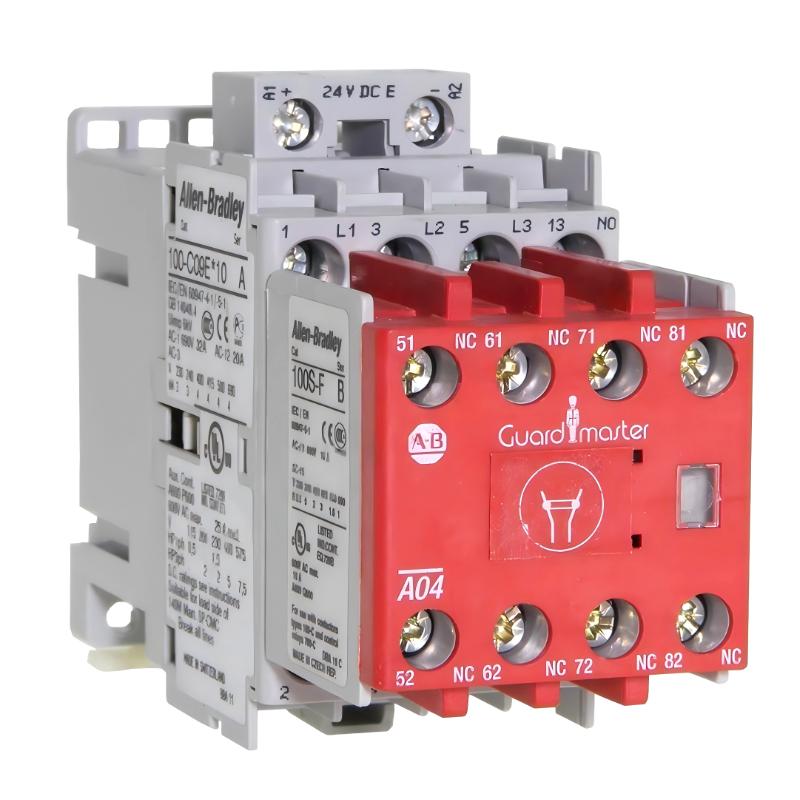
Table of Contents
- Installation Overview of 100S-C09EJ14C Safety Contactor
- Role in Emergency Stop & Safety Control System
- Pre-Installation Checks & Safety Requirements
- Mechanical Mounting & Control Cabinet Layout
- Safety Circuit Wiring & Coil Control Logic
- Commissioning & Functional Safety Testing
- FAQs on 100S-C09EJ14C Installation
- Engineering Summary & Field Practices
Installation Overview of 100S-C09EJ14C Safety Contactor
Allen-Bradley 100S-C09EJ14C safety contactor is designed for emergency stop (E-Stop) and safety interlock circuits. Correct installation is critical because even minor wiring or control logic errors can lead to unsafe machine behavior. Field experience shows that most issues originate from incorrect coil wiring or improper safety relay integration rather than the contactor itself.
Role in Emergency Stop & Safety Control System
The 100S-C09EJ14C ensures safe power isolation of actuators during emergency conditions. It works together with safety relays or safety PLC outputs to disconnect hazardous loads instantly. In real production lines, it is commonly used for motor power isolation, conveyor shutdown, and machine guarding systems.
Pre-Installation Checks & Safety Requirements
- Verify system is fully powered down and locked out (LOTO procedure)
- Confirm safety category requirements (ISO 13849 / IEC 62061)
- Inspect contactor rating vs actual load current
- Check coil voltage specification (typically 24V DC control)
- Prepare arc suppression components for inductive loads
Mechanical Mounting & Control Cabinet Layout
- Mount contactor on DIN rail with firm locking mechanism
- Maintain vertical orientation for proper heat dissipation
- Ensure spacing between contactors to avoid thermal buildup
- Avoid installation near high-vibration components like transformers
In one commissioning case, poor spacing caused overheating and intermittent coil dropouts during continuous operation.
Safety Circuit Wiring & Coil Control Logic
Proper wiring is essential for functional safety performance:
- Connect coil control through certified safety relay output
- Ensure dual-channel safety loop where required
- Use correctly rated wire for coil and load circuits
- Keep safety wiring physically separated from power cables
Field example: incorrect single-channel wiring caused unexpected restart behavior after E-stop reset until corrected to dual-channel configuration.
Commissioning & Functional Safety Testing
- Test E-stop circuit under no-load condition first
- Verify contactor dropout time after safety signal removal
- Measure coil voltage stability during switching cycles
- Check auxiliary contact feedback consistency in safety PLC
- Perform full load shutdown test under operational conditions
SAFETY_COMMISSION /MODEL=100S-C09EJ14C /E_STOP_TEST /COIL_MONITOR /LOAD_SIMULATION
FAQs on 100S-C09EJ14C Installation
Can this contactor be used without a safety relay?
No. It must be controlled by a certified safety relay or safety PLC output for compliance with safety standards.
What happens if coil wiring is reversed?
Coil reversal may prevent proper activation or cause unstable switching behavior in safety circuits.
Is arc suppression necessary?
Yes. Especially for inductive or DC loads, suppression components significantly improve contact life and reliability.
Engineering Summary & Field Practices
The Allen-Bradley 100S-C09EJ14C safety contactor is a critical component in emergency stop systems. Correct installation requires strict adherence to safety standards, proper wiring architecture, and careful commissioning. Field experience shows that most safety-related issues stem from wiring design and integration errors rather than device failure, making structured installation and testing essential for reliable machine safety performance.