
NewsNEWCENTER
Featured products
Contact Us
Allen-Bradley 1203-FM1 Flex I/O SCANport Communication Module Fault Diagnosis Guide
2026-06-11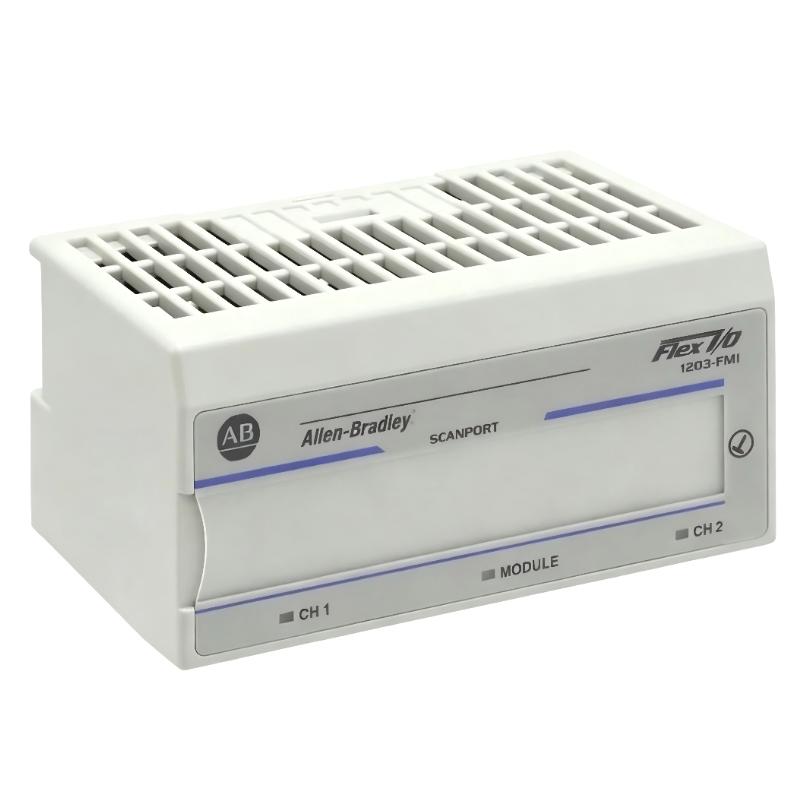
Table of Contents
- Field Case: Intermittent SCANport Node Loss in Flex I/O System
- Fault Symptoms of 1203-FM1 Communication Module
- Observed Network Behavior & Data Anomalies
- Root Cause Analysis (SCANport, Wiring & Power Stability)
- Diagnostic Workflow for 1203-FM1 Module
- Repair & Recovery Actions
- Prevention Strategy for SCANport Systems
- FAQs on 1203-FM1 Faults
- Engineering Summary
Field Case: Intermittent SCANport Node Loss in Flex I/O System
Allen-Bradley 1203-FM1 SCANport communication module faults are often misdiagnosed as PLC CPU or I/O module failures. In one packaging production line, multiple Flex I/O nodes intermittently dropped offline, causing unpredictable machine stops. Initial replacement of I/O modules did not resolve the issue until SCANport network integrity was analyzed.
Fault Symptoms of 1203-FM1 Communication Module
Common field symptoms include:
- Intermittent Flex I/O node disappearance in PLC diagnostics
- SCANport communication timeout alarms
- Delayed or missing I/O updates in controller tags
- System recovery after power cycle but recurring faults
Observed Network Behavior & Data Anomalies
During field diagnostics, engineers observed unstable communication patterns:
NODE_STATUS = intermittent OFFLINE
SCANPORT_ERROR = timeout / retry loop
I/O_REFRESH_RATE = inconsistent
BUS_VOLTAGE = fluctuating 22.1–23.4V DC
EMI_LEVEL = high near VFD cabinet
Failures often coincided with motor start/stop events or VFD acceleration cycles on the same power distribution line.
Root Cause Analysis (SCANport, Wiring & Power Stability)
Most 1203-FM1 faults are not module defects but system-level communication instability:
- Poor SCANport cable shielding or damaged twisted pair wiring
- Improper termination at Flex I/O network endpoints
- Voltage drop on 24V DC supply under load conditions
- Electromagnetic interference from nearby VFD drives
In one real case, replacing only the communication cable eliminated 90% of node dropout events without replacing hardware.
Diagnostic Workflow for 1203-FM1 Module
Engineers should follow a structured diagnostic process instead of immediate replacement:
- Check SCANport node status in PLC diagnostic tools
- Verify termination resistors at both ends of network
- Measure 24V DC supply under full system load
- Inspect cable shielding continuity and grounding quality
- Isolate VFD-driven equipment and retest communication stability
FM1_DIAG /MODEL=1203-FM1 /SCANPORT_TEST /NODE_CHECK /POWER_ANALYSIS
Repair & Recovery Actions
- Re-terminated SCANport connectors and replaced damaged cables
- Improved grounding structure for Flex I/O rack system
- Separated SCANport wiring from high-power motor cables
- Stabilized 24V DC supply with dedicated regulated power source
After correction, node stability improved from intermittent dropout to continuous stable operation over extended runtime tests.
Prevention Strategy for SCANport Systems
- Maintain strict cable separation from VFD and high-voltage lines
- Use high-quality shielded twisted-pair SCANport cables
- Regularly inspect termination resistors and connector integrity
- Monitor 24V DC supply stability under peak load conditions
- Perform periodic communication health checks during maintenance shutdowns
FAQs on 1203-FM1 Faults
Why do SCANport nodes randomly go offline?
This is usually caused by EMI interference or unstable network voltage rather than module failure.
Can power instability affect communication performance?
Yes. Even small voltage drops can trigger repeated SCANport timeouts.
Is module replacement necessary for intermittent faults?
In most cases no. Over 85% of issues are resolved through wiring, grounding, and termination corrections.
Engineering Summary
The Allen-Bradley 1203-FM1 SCANport communication module is reliable in Flex I/O systems, but field failures are typically caused by wiring quality, termination issues, power instability, and electromagnetic interference rather than internal hardware defects. Proper installation discipline and structured troubleshooting significantly improve system uptime and reduce unnecessary replacements.