
NewsNEWCENTER
Featured products
Contact Us
Emerson KL3021X1-BA1 CHARM Analog Input Card Installation Guide
2026-11-19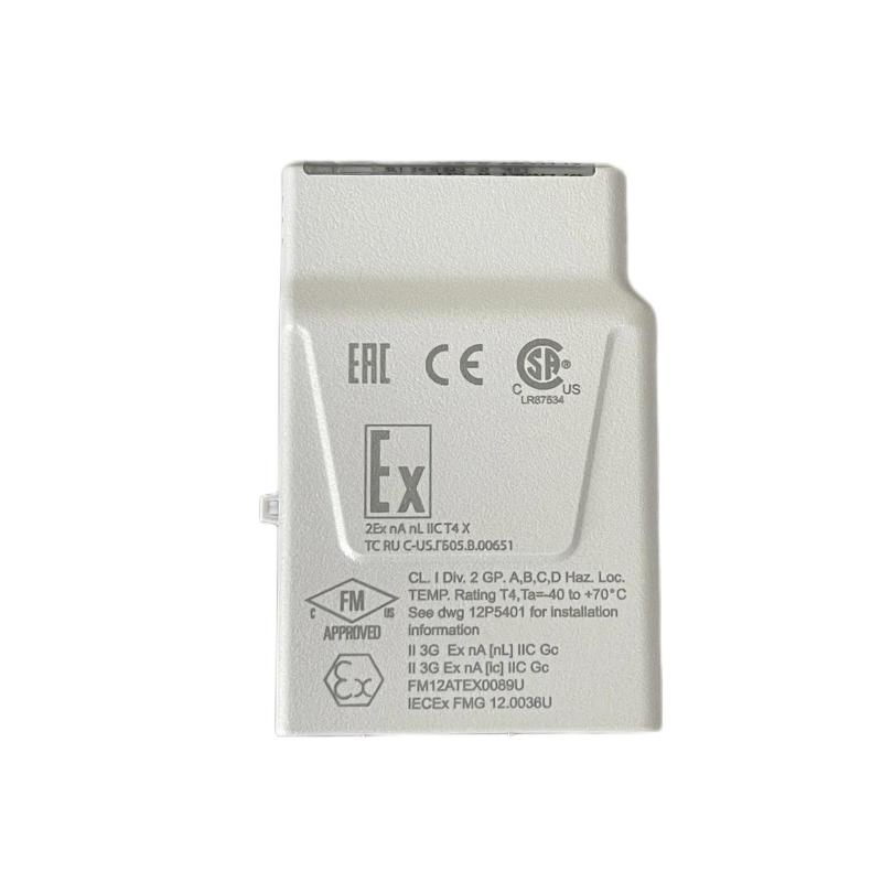
The Emerson KL3021X1-BA1 is a DeltaV CHARM analog input module designed to receive 4–20 mA field signals. It provides a channel-level interface between analog field instruments, such as pressure transmitters, flow transmitters, and temperature transmitters with current outputs, and the DeltaV control system. Correct installation requires a compatible CHARM terminal block, correct mechanical keying, verified field wiring, and accurate channel configuration.
Emerson KL3021X1-BA1 Analog Input CHARM Identification
The KL3021X1-BA1 converts a field-level 4–20 mA measurement into an analog input value available to the DeltaV system. Unlike a conventional multi-channel I/O card, a CHARM is a channel-level I/O component installed on a compatible terminal block within the Electronic Marshalling architecture.
This arrangement allows individual field signals to be terminated and assigned through the CHARM system. The KL3021X1-BA1 is intended for analog current input applications. Its product designation is associated with the AI 4–20 mA HART CHARM, but the availability of HART communication depends on the installed system, interface, and application configuration. Do not assume that every connected device or host application will expose HART functions.
- Manufacturer: Emerson
- Model: KL3021X1-BA1
- Product type: CHARM Analog Input Module
- Signal type: 4–20 mA analog input
- Platform: DeltaV Electronic Marshalling
- Terminal block key position: 1A
KL3021X1-BA1 Electrical and Environmental Specifications
Before installing the module, confirm that the electrical and environmental conditions are compatible with the cabinet and field instrument. The following values are identified in the product instruction information and should be checked against the documentation revision applicable to the installed unit.
| Parameter | Specification |
|---|---|
| Input signal | 4–20 mA |
| CHARM bus power | +6.3 VDC at 32 mA |
| Field circuit rating | +24 VDC at 25 mA |
| Terminal block key position | 1A |
| Ambient operating temperature | -40 °C to +70 °C |
| Relative humidity | 5–95%, non-condensing |
| Shock resistance | 10 g, half-sine wave, 11 ms |
| Vibration resistance | 1 mm peak-to-peak from 2 to 13.2 Hz; 0.7 g from 13.2 to 150 Hz |
| Airborne contaminants | ISA-S71.04-1985 Class G3 |
The field circuit rating is not a substitute for checking the transmitter’s actual power requirements and loop design. Verify the permitted loop arrangement and wiring against the applicable Emerson installation documentation.
KL3021X1-BA1 Pre-Installation Checks
Preparation should begin with the cabinet drawings, I/O assignment schedule, and field loop documentation. Confirm that the intended channel is configured for a 4–20 mA input and that the selected terminal block is compatible with the KL3021X1-BA1.
- Check the complete module part number and product label.
- Confirm the DeltaV CHARM I/O carrier and terminal block arrangement.
- Verify that the terminal block supports the required analog input CHARM.
- Inspect the CHARM contacts and terminal block connector for damage or contamination.
- Review the field instrument’s current output, supply requirements, and loop drawing.
- Check cabinet temperature, humidity, ventilation, and installation conditions.
- Review hazardous-area requirements before handling equipment installed in a classified location.
Do not install the module if the terminal block keying, product identity, or field wiring arrangement is uncertain. Resolve any mismatch using the approved hardware documentation.
Emerson KL3021X1-BA1 CHARM Mounting and Keying
The KL3021X1-BA1 is installed on a compatible CHARM terminal block. The mechanical keying system helps prevent an incompatible CHARM type from being fitted to a terminal block configured for another signal function. The specified key position for this analog input CHARM is 1A.
- Identify the designated terminal block and channel position.
- Verify the terminal block keying against the approved hardware arrangement.
- Inspect the mating contacts and mechanical surfaces.
- Align the CHARM with the terminal block without applying excessive force.
- Seat the module fully and check that it is mechanically secure.
- Confirm that the module identification and channel assignment match the engineering records.
The terminal block keys are automatically set when a CHARM is first installed. Changing the CHARM type requires the prescribed key-reset procedure. Do not modify or force the keying to accommodate an unverified combination.
KL3021X1-BA1 4–20 mA Field Wiring and Loop Connections
The field wiring arrangement must follow the terminal assignment for the specific CHARM terminal block and DeltaV configuration. A typical 4–20 mA loop includes a transmitter, loop power source, field conductors, and the analog input channel. The exact connection method depends on whether the transmitter is two-wire, three-wire, or externally powered.
Wiring preparation
- Confirm the transmitter output is configured for a 4–20 mA signal.
- Identify the positive and return conductors from the approved loop drawing.
- Verify whether the transmitter uses loop power or an independent supply.
- Check cable continuity and insulation using an approved test procedure.
- Use the specified conductor size and termination method.
- Keep analog signal cables routed appropriately in relation to high-noise power wiring.
- Label both ends of the field cable with the correct loop and channel identification.
Do not infer terminal numbers from another CHARM model. Use the terminal block wiring diagram for the exact hardware combination. Incorrect polarity or an incompatible external supply arrangement may prevent a valid input reading or damage connected equipment.
DeltaV System Configuration and KL3021X1-BA1 Commissioning
After mechanical installation and wiring inspection, configure the DeltaV channel according to the project engineering database. The configured signal type, channel assignment, scaling, and engineering units must agree with the field instrument and process documentation.
- Confirm the installed CHARM is recognized by the DeltaV system.
- Verify the module identity and assigned I/O channel.
- Set the channel for the intended 4–20 mA input application.
- Enter the correct process range and engineering units.
- Check alarm limits and signal-quality handling where required.
- Verify the transmitter’s configured output range.
- Review available module diagnostics and communication status.
- Complete the approved loop test before releasing the channel for normal operation.
Where HART functionality is required, confirm that the installed DeltaV hardware, software, and engineering configuration support the intended HART functions. A CHARM product description containing “HART” does not by itself establish that every host system or third-party monitoring application supports HART access.
KL3021X1-BA1 Signal Testing and Installation Validation
Signal validation should confirm that the field transmitter, wiring, CHARM, and DeltaV configuration operate as one complete measurement loop. Use an approved loop calibrator or transmitter test method, following the site’s isolation and process-control requirements.
Typical 4–20 mA scaling reference
| Current signal | Percentage of span | Expected interpretation |
|---|---|---|
| 4 mA | 0% | Lower range value |
| 8 mA | 25% | Quarter scale |
| 12 mA | 50% | Mid-scale |
| 16 mA | 75% | Three-quarter scale |
| 20 mA | 100% | Upper range value |
These are standard linear 4–20 mA scaling reference points, not guaranteed measured readings from a particular installation. The expected process value depends on the configured lower and upper range values.
Final acceptance checks
- Correct KL3021X1-BA1 model and terminal block combination
- Correct key position and secure mounting
- Field wiring checked against the loop diagram
- Correct 4–20 mA channel configuration
- Signal values verified at representative test points
- Engineering units and process scaling confirmed
- No unexplained module or channel diagnostic alarms
- Commissioning results recorded and approved
Emerson KL3021X1-BA1 Installation FAQs
What is the KL3021X1-BA1 used for?
It is a DeltaV CHARM analog input module designed for 4–20 mA field signals. It allows compatible analog transmitters to provide measurement values to the control system.
Does the KL3021X1-BA1 support HART?
The module is identified as an AI 4–20 mA HART CHARM in its product documentation. Actual HART access depends on the DeltaV hardware, software, and application configuration. Some third-party applications specifically list this CHARM without HART support, so confirm the intended host-system capability.
What is the terminal block key position?
The specified terminal block key position is 1A. Confirm the terminal block arrangement before installation.
What is the CHARM bus power requirement?
The documented CHARM bus power rating is +6.3 VDC at 32 mA.
What is the field circuit rating?
The documented field circuit rating is +24 VDC at 25 mA. Check the complete loop design and transmitter requirements before connecting a field device.
Can the KL3021X1-BA1 be installed on any CHARM terminal block?
No. Use a compatible terminal block with the correct mechanical keying and approved hardware arrangement.
Does the module require calibration?
The product instruction information states that calibration is not required. Field transmitters and the overall measurement loop may still require calibration or verification according to the site’s maintenance program.
Can the module be repaired internally?
The product documentation states that the unit contains no user-serviceable parts and should not be disassembled. Replace or service it according to the manufacturer’s instructions.
Can it be inserted or removed while energized?
Hazardous-area restrictions apply. The instruction sheet states that removal or insertion is not permitted with system power energized unless the area is known to be non-hazardous. Follow the applicable site procedure and current product instructions.
What should be checked if the DeltaV reading is incorrect?
Check the transmitter output, loop wiring, polarity, terminal block seating, channel assignment, scaling, engineering units, and system diagnostics.
Emerson KL3021X1-BA1 Installation Conclusion
The Emerson KL3021X1-BA1 CHARM Analog Input Card provides a compact 4–20 mA measurement interface for DeltaV Electronic Marshalling systems. Reliable commissioning depends on compatible terminal block selection, correct 1A keying, verified loop wiring, accurate channel scaling, and appropriate hazardous-area controls. By validating the complete field-to-controller signal path, engineers can establish dependable analog measurement and simplify future maintenance.