
NewsNEWCENTER
Featured products
Contact Us
Emerson KL3021X1-BA1 Analog Input Card Troubleshooting Guide
2026-11-19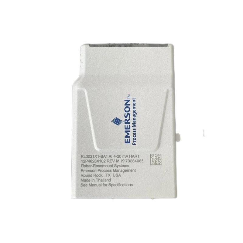
The Emerson KL3021X1-BA1 CHARM Analog Input Card is designed to receive 4–20 mA field signals in a DeltaV Electronic Marshalling system. When a process value is missing, unstable, inaccurate, or accompanied by an I/O diagnostic alarm, troubleshooting should examine the transmitter, field loop, terminal block, CHARM installation, and DeltaV channel configuration together. Replacing the input module without checking these elements can leave the original fault unresolved.
KL3021X1-BA1 Common Analog Input Fault Symptoms
Problems associated with the KL3021X1-BA1 may appear at the instrument, I/O channel, or operator interface. The first task is to determine whether the fault affects one channel, several channels, or the complete CHARM I/O assembly.
- No signal: The DeltaV channel displays no valid process measurement.
- Low input: The reported value remains below the expected process range.
- High input: The displayed value exceeds the expected measurement range.
- Unstable reading: The process value fluctuates despite relatively stable process conditions.
- Incorrect scaling: The displayed engineering value does not correspond to the transmitter output.
- Module diagnostic: The CHARM or I/O channel reports an abnormal hardware or signal condition.
- Communication issue: Expected device information or HART-related functions are unavailable in the host application.
Record the channel number, time of occurrence, alarm text, process condition, and recent maintenance activity. These details help identify whether the issue is continuous, intermittent, or related to a specific operating condition.
Emerson KL3021X1-BA1 Fault: No Signal or Zero Reading
A zero or missing reading can result from a disconnected transmitter, an open loop, missing field power, incorrect polarity, or a problem at the terminal block. It can also occur when the DeltaV channel is assigned or configured incorrectly.
Possible causes
- Transmitter power is unavailable.
- The 4–20 mA loop is open or incorrectly terminated.
- Positive and return conductors are connected incorrectly.
- A field cable or terminal connection is damaged.
- The CHARM is not seated correctly.
- The terminal block is incompatible or incorrectly keyed.
- The channel is assigned to the wrong instrument or configuration.
Diagnostic procedure
- Check the transmitter’s local display or status indication, if available.
- Verify the field-device power supply and loop arrangement.
- Inspect the wiring against the approved loop drawing.
- Check the terminal block and CHARM seating under the approved isolation procedure.
- Use an approved loop test method to determine whether current is present in the circuit.
- Review DeltaV channel status and configuration.
If the transmitter is producing a valid current but the control system does not display the expected measurement, investigate the wiring, CHARM installation, and channel configuration before concluding that the transmitter is defective.
KL3021X1-BA1 Incorrect, Fluctuating, or Out-of-Range Measurements
An analog input may remain operational while reporting an incorrect process value. This type of fault often involves signal scaling, electrical interference, transmitter configuration, grounding, or an unstable loop supply.
Check the transmitter range and DeltaV scaling
A standard linear 4–20 mA signal represents the configured lower and upper range values. For example, if a transmitter is configured for 0–100 engineering units, 4 mA represents 0 units, 12 mA represents 50 units, and 20 mA represents 100 units.
| Input current | Example process value |
|---|---|
| 4 mA | 0 units |
| 8 mA | 25 units |
| 12 mA | 50 units |
| 16 mA | 75 units |
| 20 mA | 100 units |
This is an illustrative linear scaling example. Actual engineering values depend on the configured transmitter range and DeltaV channel settings.
Other possible causes
- Incorrect transmitter lower or upper range values
- Wrong engineering units or scaling parameters
- Electrical noise from nearby switching or motor circuits
- Poor cable shielding or grounding arrangements
- Loose terminals or damaged conductors
- Unstable transmitter power
- Actual process fluctuations or a faulty sensing element
Compare the transmitter output with the value displayed by DeltaV using an approved test method. If the current is stable but the displayed engineering value is wrong, examine the configured range and scaling before replacing hardware.
KL3021X1-BA1 4–20 mA Loop and Wiring Fault Diagnosis
The analog input depends on a complete electrical loop. A fault anywhere between the transmitter and the CHARM terminal block can affect the measurement. Wiring checks should be carried out according to the approved loop drawing and site isolation procedure.
Common wiring-related problems
- Open circuit: A broken conductor or disconnected terminal interrupts the current loop.
- Incorrect polarity: Reversed connections may prevent the expected signal from being received.
- Loose termination: Poor contact can cause intermittent or fluctuating readings.
- Short circuit: Damaged insulation or incorrect termination can disrupt the loop.
- Grounding issue: An unsuitable grounding or shielding arrangement can introduce noise or measurement instability.
- Incorrect external supply: An incompatible power arrangement can prevent correct transmitter operation.
Recommended inspection sequence
- Identify the affected loop from the cabinet wiring schedule.
- Confirm whether the transmitter is loop-powered or externally powered.
- Check the wiring route and terminal assignments.
- Inspect conductors and termination points for physical damage.
- Perform continuity or loop measurements only when permitted by the approved procedure.
- Compare the measured signal with the transmitter’s expected output.
Do not connect an external current source or voltage source directly to the CHARM terminals unless the manufacturer documentation explicitly describes that test arrangement.
Emerson KL3021X1-BA1 CHARM and Terminal Block Problems
The KL3021X1-BA1 must be installed on a compatible CHARM terminal block. The mechanical keying system helps prevent an incompatible CHARM type from being installed on a terminal block intended for another signal type. The specified key position for this model is 1A.
Mechanical and hardware checks
- Verify that the installed module is KL3021X1-BA1.
- Check that the terminal block is compatible with the analog input CHARM.
- Inspect the CHARM contacts and terminal block connector.
- Confirm that the module is fully seated.
- Look for visible signs of corrosion, contamination, or physical damage.
- Compare the installed arrangement with the approved DeltaV hardware drawings.
Do not force the CHARM into a terminal block when the keying does not match. The product instruction information explains that terminal block keys are set when a CHARM is first installed. Resetting the keying for a different CHARM type requires the specified procedure.
The module documentation states that the unit contains no user-serviceable parts and should not be disassembled. It also states that calibration is not required. If an internal module fault is confirmed, follow the manufacturer’s replacement or service procedure.
DeltaV Diagnostics and HART Communication Troubleshooting
DeltaV system diagnostics can help distinguish a field-loop problem from a CHARM or system configuration issue. Review the channel status, module identification, and alarm history before making hardware changes.
DeltaV diagnostic checks
- Confirm that the correct CHARM is recognized by the system.
- Check the assigned I/O channel and instrument tag.
- Review channel-level diagnostic messages.
- Compare the displayed input with the expected transmitter current.
- Verify the configured measurement range and engineering units.
- Check whether the problem is limited to one channel or affects multiple channels.
HART-related considerations
The KL3021X1-BA1 is identified in its product documentation as an AI 4–20 mA HART CHARM. However, HART access is dependent on the installed DeltaV system, host software, and application configuration. Some third-party applications list this CHARM for 4–20 mA input use while explicitly stating that HART is not supported in that application. Therefore, a missing HART diagnostic or device variable should not automatically be treated as an analog input hardware failure.
- Confirm that the connected field instrument supports HART.
- Verify that the loop and host configuration are suitable for HART communication.
- Check the host application’s supported CHARM functions.
- Separate analog current measurement faults from digital communication faults.
KL3021X1-BA1 Step-by-Step Troubleshooting Workflow
Use the following sequence to locate the source of a signal problem while minimizing unnecessary disturbance to the control system.
- Record the symptom: Identify whether the channel has no signal, an incorrect value, an unstable reading, or a diagnostic alarm.
- Check instrument operation: Confirm that the field transmitter is powered and functioning.
- Verify the loop: Review the wiring diagram, polarity, field supply, and termination points.
- Measure the signal: Use an approved loop calibrator or measurement method to check the actual current.
- Inspect the CHARM assembly: Verify module identity, terminal block compatibility, key position, and seating.
- Review DeltaV configuration: Confirm channel assignment, signal type, scaling, and engineering units.
- Check system diagnostics: Record module and channel alarms and compare them with the electrical findings.
- Correct the identified fault: Repair wiring, correct configuration, or replace damaged hardware as appropriate.
- Repeat the loop test: Verify representative current points and confirm the corresponding process values.
- Document the result: Record measurements, corrective actions, and final channel status.
Illustrative engineering scenario: Incorrect process reading
The following is a hypothetical example rather than a report from a specific customer installation. A pressure transmitter is connected to a KL3021X1-BA1 channel. The DeltaV display shows a value that is consistently lower than the expected process measurement. The technician checks the transmitter configuration and confirms that its output is within the expected current range. The next check reveals that the DeltaV channel’s configured upper range does not match the transmitter’s upper range. After the configuration is corrected through the approved engineering process, the technician repeats the loop test and confirms that the displayed value follows the expected scaling.
This scenario illustrates why an incorrect process value should be investigated as both an electrical signal problem and a configuration problem.
Example troubleshooting record
Equipment: Emerson DeltaV CHARM Analog Input
Model: KL3021X1-BA1
Signal type: 4-20 mA
Affected channel: _______________________
Field instrument tag: ___________________
Reported symptom: ______________________
Measured loop current: __________________
Configured lower range: _________________
Configured upper range: _________________
Terminal block key position: 1A
DeltaV diagnostic: ______________________
Corrective action: ______________________
Final loop test result: _________________
Fill in the record using actual measurements and verified configuration data. Do not use assumed terminal assignments or estimated electrical values as proof of successful repair.
Emerson KL3021X1-BA1 Troubleshooting FAQs
Why does the KL3021X1-BA1 show a zero reading?
Possible causes include missing transmitter power, an open current loop, incorrect wiring, poor terminal contact, an incorrectly seated CHARM, or an incorrect channel assignment. Check the field loop before replacing the module.
What causes a fluctuating 4–20 mA input?
Potential causes include unstable transmitter output, loose wiring, electrical interference, poor grounding, or an unstable field supply. Compare the actual loop current with the DeltaV reading.
How can I identify a scaling problem?
Compare the transmitter’s configured lower and upper range values with the DeltaV channel scaling. Use known current test points to verify the corresponding engineering values.
Does the KL3021X1-BA1 require calibration?
The product instruction information states that calibration is not required for the CHARM itself. The connected transmitter and complete measurement loop may still require calibration or verification under the site’s maintenance program.
What is the correct terminal block key position?
The specified key position is 1A. Verify that the terminal block and CHARM are compatible before installation or replacement.
Can a faulty terminal block cause an incorrect analog reading?
Yes. A poor connection, damaged contact, incorrect termination, or incompatible terminal block can interrupt or distort the field signal.
Does the module support HART communication?
The product is identified as an AI 4–20 mA HART CHARM. Actual HART functionality depends on the host system and application. Confirm support in the applicable DeltaV and software documentation.
Can I repair the CHARM by replacing internal components?
The product instructions state that the module has no user-serviceable parts and should not be disassembled. Use the manufacturer’s approved replacement or service process.
Can the module be removed while the system is energized?
Hazardous-area restrictions apply. The instruction sheet states that the unit must not be removed or inserted with system power energized unless the area is known to be non-hazardous. Follow the current product instructions and site safety procedures.
When should the KL3021X1-BA1 be replaced?
Replacement should be considered when the module is correctly identified and installed, the field loop and configuration have been verified, and evidence indicates a hardware fault. The module should not be opened for internal repair.
Emerson KL3021X1-BA1 Troubleshooting Conclusion
Effective troubleshooting of the Emerson KL3021X1-BA1 CHARM Analog Input Card requires a complete review of the 4–20 mA signal path, from the field transmitter to the DeltaV operator display. Check loop power, polarity, wiring, terminal block compatibility, CHARM seating, channel scaling, and system diagnostics before replacing hardware. For HART-related issues, verify host-system support separately from the analog input function. A structured diagnostic process helps restore reliable measurements while reducing unnecessary maintenance work.