
NewsNEWCENTER
Featured products
Contact Us
Foxboro FCM2F2 P0914YZ Fiber Optic Fieldbus Extender Installation and Commissioning Guide
2026-11-12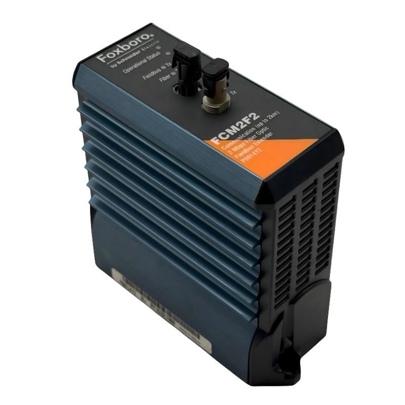
1. Product Overview
The Foxboro FCM2F2 P0914YZ is a Fieldbus Communications Module designed for Foxboro I/A Series distributed control systems. It functions as a fiber optic fieldbus extender, allowing remote 200 Series Fieldbus Modules (FBMs) to communicate with the control system through fiber optic connections.
By extending the fieldbus between separate baseplates, the FCM2F2 makes it possible to locate I/O modules closer to field instruments and process equipment. This arrangement can reduce long copper signal cable runs and simplify the distribution of I/O across multiple control cabinets or plant areas.
The FCM2F2 supports a nominal communication rate of 2 Mbps and a maximum baseplate-to-baseplate fiber distance of up to 2 km under the specified cable and installation conditions. It uses multimode graded-index glass fiber and ST-type optical connectors. Fiber communication also provides electrical isolation between connected locations, helping reduce the effects of electromagnetic interference, lightning-related disturbances, and ground potential differences.
2. Main Functions and Applications
The FCM2F2 is primarily used to extend the Foxboro 200 Series module fieldbus between local and remote I/O baseplates. Typical applications include:
- Connecting remote FBM baseplates to a central control system.
- Distributing I/O modules across separate industrial control cabinets.
- Extending fieldbus communication between different plant areas.
- Reducing long-distance copper fieldbus wiring.
- Providing electrical isolation between geographically separated equipment.
- Supporting redundant fieldbus communication architectures when installed in the required configuration.
3. Technical Specifications
| Parameter | Specification |
|---|---|
| Manufacturer | Foxboro |
| Model | FCM2F2 |
| Part number supplied | P0914YZ |
| Product type | Fieldbus Communications Module |
| System platform | Foxboro I/A Series 200 Series |
| Primary function | Fiber optic fieldbus extension between baseplates |
| Communication rate | 2 Mbps |
| Maximum nominal fiber distance | Up to 2 km baseplate-to-baseplate |
| Fiber type | Multimode graded-index glass fiber |
| Typical fiber core/cladding | 62.5/125 μm |
| Optical connector | ST type |
| Redundancy | Supported through paired module configuration |
| Related model | FCM2F4 and FCM2F10, with different distance and fiber requirements |
Catalog-number markings and associated hardware revisions should be checked against the actual module label and system documentation. Some product documentation identifies the FCM2F2 using the associated designation RH914YZ, while the supplied part number is P0914YZ. Confirm the exact identification before ordering or replacing a module.
4. Pre-Installation Preparation
Before installing the FCM2F2, verify the system architecture and prepare the optical communication path. A fiber extender must be correctly matched to the remote baseplate arrangement; simply connecting two optical cables does not guarantee a working fieldbus link.
Hardware verification
- Confirm that the module is an FCM2F2 and check its complete part number and hardware revision.
- Verify that the receiving baseplate supports the FCM2F2 and the intended FBM configuration.
- Check whether the installation is non-redundant or redundant.
- Confirm the number and position of FCM modules required at each end of the fiber link.
- Check the compatibility of associated 200 Series FBMs and fieldbus equipment.
Fiber cable preparation
- Use multimode graded-index glass fiber suitable for the FCM2F2.
- Confirm the specified 62.5/125 μm fiber characteristics and optical performance.
- Use ST-type connectors at the module interfaces.
- Verify that the total optical path is within the specified 2 km maximum distance.
- Check connector cleanliness, cable condition, routing, and mechanical protection.
Do not substitute single-mode fiber or a different connector type without confirming that the complete optical link is specifically designed and approved for that combination.
5. Safety and Handling Requirements
Installation should be performed by qualified industrial automation technicians familiar with Foxboro I/A Series hardware and fiber optic communication systems.
- Obtain the required maintenance authorization before modifying an operating control system.
- Evaluate process conditions and place affected equipment in an approved maintenance state.
- Isolate electrical power where required by the applicable installation procedure.
- Follow ESD precautions when handling the electronic module.
- Never look directly into an optical fiber or transmitter port.
- Keep fiber connectors covered when disconnected.
- Avoid bending, crushing, twisting, or pulling fiber optic cables beyond their specified limits.
- Do not force the module into the baseplate or apply excessive force to optical connectors.
Do not assume that the FCM2F2 supports hot insertion or removal. Live replacement is permitted only when the exact Foxboro system documentation and approved site procedure explicitly authorize it.
6. FCM2F2 Installation Procedure
Step 1: Identify the baseplate locations
Identify the local and remote baseplates that will be connected through the fiber link. Check the system layout drawings and confirm the designated FCM positions. Make sure the selected baseplates are designed to support the required FCM and FBM combination.
Step 2: Confirm the fieldbus topology
Determine whether the connection is non-redundant or redundant. A non-redundant connection generally requires one FCM2F2 at each end of the fiber link. A redundant arrangement uses separate A and B communication paths, with the corresponding FCM modules installed at both ends.
Step 3: Inspect the baseplate
Check the module mounting position, electrical connectors, retaining hardware, and surrounding components. Remove foreign material only through an approved maintenance method. If the baseplate connector is damaged, stop the installation until the problem is corrected.
Step 4: Install the FCM2F2
Align the module with the designated mounting guides and electrical connector. Insert it evenly and secure it using the specified retaining mechanism. Confirm that the module is fully seated and that no connector damage has occurred.
Step 5: Connect the fiber optic cable
Identify the transmit and receive optical ports on the module. Connect the fiber cable according to the approved system topology and wiring drawings. The transmit path at one end must connect to the corresponding receive path at the other end. Check the A and B path assignments separately in redundant installations.
Step 6: Secure and inspect the cable route
Route the fiber through the designated cable path. Maintain the required bend radius and protect the cable from sharp edges, excessive tension, crushing, and mechanical vibration. Label both ends so that future maintenance personnel can identify the correct communication path.
Step 7: Complete the installation inspection
Check module seating, optical connector engagement, cable identification, and the overall installation condition. Confirm that the local and remote ends follow the same approved topology before restoring the system to operation.
7. Fiber Optic Cable and Network Design
Correct fiber selection is essential to reliable FCM2F2 communication. The module is designed for multimode graded-index glass fiber. The cable characteristics and connector arrangement must match the optical interface requirements.
| Item | Installation consideration |
|---|---|
| Fiber category | Multimode graded-index glass fiber |
| Core and cladding | Typical specified construction: 62.5/125 μm |
| Connector | ST-type optical connector |
| Distance | Up to 2 km between baseplates |
| Optical loss | Must remain within the applicable link budget |
| Cable protection | Protect against bending, crushing, moisture, and mechanical damage |
| Connector maintenance | Keep end faces clean and protected from dust |
Fiber loss should be evaluated using the cable manufacturer’s specifications and the applicable Foxboro optical requirements. Connector losses, splices, patch panels, and other intermediate connections must be included in the overall link assessment.
The FCM2F4 and FCM2F10 are related models, but they are not interchangeable with the FCM2F2 without checking the complete system design. The FCM2F4 supports a different nominal distance using multimode fiber, while the FCM2F10 is intended for a longer-distance single-mode fiber application.
8. Redundant and Non-Redundant Configuration
The FCM2F2 can be used in both non-redundant and redundant fieldbus arrangements. The number of modules and fiber paths depends on the intended system availability design.
Non-redundant configuration
A basic non-redundant connection uses one FCM2F2 on each baseplate. One optical communication path links the local and remote locations. This arrangement is suitable where a single fieldbus path is accepted by the system design.
Redundant configuration
A redundant arrangement uses separate FCM modules for the A and B fieldbus paths. For a fiber connection between two baseplates, this generally requires a pair of FCM modules at each end, giving four modules in total.
Redundant paths should be routed and identified separately according to the approved engineering design. Avoid routing both paths through a single unprotected cable section where a single physical failure could interrupt both connections.
Do not assume that adding a second FCM automatically creates a functional redundant system. The controller configuration, baseplate arrangement, fieldbus topology, and associated equipment must all support the intended redundancy scheme.
9. Power-Up and Commissioning
After installation, restore the system according to the approved startup sequence. The FCM2F2 should be evaluated at both ends of the fiber connection, because a fault at either end can prevent normal communication.
- Confirm that all modules are correctly installed and secured.
- Check that the fiber cables are connected to the intended transmit and receive ports.
- Verify that the optical paths are assigned correctly for the A and B fieldbus connections, where applicable.
- Restore power according to the system startup procedure.
- Observe the FCM2F2 operational status indicators.
- Check the fieldbus transmit and receive activity indicators.
- Confirm that the local and remote baseplates are recognized by the control system.
- Verify communication with the associated FBMs.
- Review the system diagnostic display for communication or module alarms.
- Complete the approved functional checks before returning the process to normal operation.
10. LED Status and Communication Verification
The FCM2F2 front panel includes operational status and fieldbus/fiber communication indicators. These indicators help maintenance personnel determine whether the module is powered, operating, and exchanging communication data.
| Indicator group | What to check |
|---|---|
| Operational Status | Confirm that the module reaches its normal operating condition after startup. |
| Fieldbus Tx | Check for transmit activity associated with the electrical fieldbus interface. |
| Fieldbus Rx | Check for received fieldbus communication activity. |
| Fiber Tx | Check for optical transmit activity toward the remote baseplate. |
| Fiber Rx | Check for optical receive activity from the remote baseplate. |
LED meanings and timing should be interpreted using the exact hardware revision documentation. A communication activity indicator that is temporarily inactive does not by itself prove that the module has failed; the actual state depends on network traffic and system operation.
11. Common Installation Mistakes
- Incorrect fiber type: Using single-mode fiber with an FCM2F2 installation designed for multimode fiber.
- Wrong connector: Installing an optical connector that does not match the module interface.
- Excessive cable distance: Designing a link beyond the specified nominal 2 km limit.
- Transmit/receive reversal: Connecting the optical paths incorrectly between the two ends.
- Incorrect redundancy wiring: Mixing A and B paths or failing to install the required paired modules.
- Dirty optical connectors: Allowing dust or contamination to increase optical loss.
- Incorrect baseplate selection: Installing the module in a position or baseplate that does not support the intended configuration.
- Unverified module substitution: Treating FCM2F2, FCM2F4, and FCM2F10 as interchangeable.
12. Maintenance Recommendations
Regular inspection helps maintain reliable communication between local and remote I/O locations.
- Inspect fiber cable routing and mechanical protection during scheduled maintenance.
- Check optical connectors for contamination or physical damage before reconnection.
- Maintain clear labels for both ends of each fiber path.
- Record module model, part number, revision, and baseplate location.
- Review communication alarms and intermittent fieldbus faults.
- Keep an updated record of redundant A and B path assignments.
- Use approved replacement modules and compatible fiber optic components.
- Verify communication after any cable, baseplate, or FCM replacement.
13. Technical FAQs
1. What is the main function of the Foxboro FCM2F2 P0914YZ?
It extends the Foxboro 200 Series module fieldbus between baseplates through fiber optic communication, allowing remote FBMs to be located closer to field equipment.
2. What is the maximum communication distance of the FCM2F2?
The FCM2F2 supports a nominal maximum baseplate-to-baseplate fiber distance of up to 2 km, subject to the specified cable and optical link requirements.
3. What type of fiber optic cable does the FCM2F2 use?
It uses multimode graded-index glass fiber. The specified installation commonly uses 62.5/125 μm fiber with ST-type connectors.
4. What is the communication speed of the FCM2F2?
The FCM2F2 operates at a nominal communication rate of 2 Mbps.
5. Can the FCM2F2 be used in a redundant fieldbus system?
Yes. Redundancy is supported through paired modules and separate A and B communication paths. The complete baseplate and controller architecture must also support the redundant arrangement.
6. How many FCM2F2 modules are required for a redundant connection between two baseplates?
A typical redundant baseplate-to-baseplate connection requires two FCM modules at each end, for a total of four modules. Confirm the exact arrangement against the system topology.
7. Can I use the FCM2F4 or FCM2F10 instead of the FCM2F2?
Not as an automatic replacement. These models have different distance capabilities and fiber requirements. Check the optical design and system documentation before substitution.
8. Why is there no communication between the two baseplates?
Possible causes include reversed transmit and receive connections, dirty fiber connectors, incorrect fiber type, excessive optical loss, damaged cable, or an incorrectly configured fieldbus path.
9. Does fiber optic communication provide electrical isolation?
Yes. The optical link separates the electrical interfaces at the connected locations, helping reduce ground-loop problems and the effects of electrical interference.
10. What should be checked after replacing an FCM2F2?
Verify the module identity and revision, baseplate compatibility, optical cable connections, A/B path assignments, operational indicators, and communication with the remote FBMs.
Technical Summary
The Foxboro FCM2F2 P0914YZ Fieldbus Communications Module provides a 2 Mbps fiber optic extension for Foxboro I/A Series 200 Series fieldbus networks. It enables remote FBM baseplates to communicate with the control system over multimode graded-index fiber, with a nominal maximum baseplate-to-baseplate distance of 2 km.
Reliable installation depends on correct baseplate selection, compatible fiber cable, ST-type connectors, accurate transmit/receive connections, and appropriate redundancy configuration. During commissioning, verify operational indicators and communication at both ends of the link. Following the approved system topology and revision-specific installation instructions helps maintain stable fieldbus communication across distributed industrial control installations.