
NewsNEWCENTER
Featured products
Contact Us
Foxboro FCM2F2 P0914YZ Fiber Optic Fieldbus Extender Troubleshooting and Fault Diagnosis Guide
2026-11-12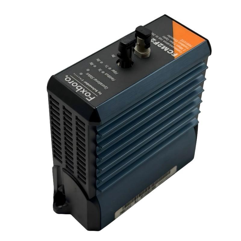
1. Introduction to FCM2F2 Troubleshooting
The Foxboro FCM2F2 P0914YZ Fieldbus Communications Module is used in Foxboro I/A Series control systems to extend communication between 200 Series Fieldbus Module (FBM) baseplates through a fiber optic link. It supports distributed I/O arrangements in which remote baseplates are installed away from the main control cabinet.
Operating at a nominal communication rate of 2 Mbps, the FCM2F2 uses multimode graded-index glass fiber to provide a communication path between baseplates. Its optical interface helps isolate the connected locations electrically while maintaining fieldbus communication.
Communication failures can originate from the FCM2F2 itself, the remote module, fiber optic cable, connector contamination, baseplate connections, or the wider fieldbus configuration. A structured diagnostic procedure is therefore essential before replacing hardware.
2. Common FCM2F2 Fault Symptoms
| Fault symptom | Possible cause | Recommended inspection |
|---|---|---|
| Remote baseplate is unavailable | Fiber link interruption, incorrect connection, or remote FCM fault | Check both FCM modules and the complete optical path |
| Intermittent fieldbus communication | Dirty optical connectors, damaged cable, excessive bending, or unstable module seating | Inspect connectors, cable routing, and module installation |
| No fiber receive activity | Remote transmitter failure, broken fiber, or reversed optical connections | Check the transmit and receive paths at both ends |
| No fiber transmit activity | Module operating condition, fieldbus traffic, or configuration problem | Check operational status and system communication activity |
| Local FBMs communicate but remote FBMs do not | Fault in the extension link or remote baseplate | Separate the local fieldbus and remote optical-link diagnostic paths |
| Redundant path unavailable | A/B path wiring error, failed module, or damaged fiber | Check each redundant path independently |
| Communication alarms after replacement | Incorrect replacement model, module revision, or installation configuration | Verify part number, compatibility, and system configuration |
| Multiple remote modules report faults | Shared baseplate, power, or fieldbus communication problem | Investigate common infrastructure before replacing individual FBMs |
3. Initial Diagnostic Procedure
Before performing detailed tests, establish whether the problem affects one module, one remote baseplate, one fiber path, or the entire fieldbus network.
- Record the exact FCM2F2 part number and hardware revision.
- Identify the local and remote baseplate locations.
- Determine whether the installation is non-redundant or redundant.
- Record the current operational and communication LED conditions.
- Check system diagnostics for fieldbus, FCM, or FBM communication alarms.
- Determine whether local FBMs are still communicating normally.
- Check whether other remote baseplates are affected.
- Review recent maintenance, cable replacement, or configuration changes.
This initial assessment helps distinguish a local FCM problem from a shared network or power issue. If multiple remote baseplates become unavailable at the same time, investigate common communication infrastructure before replacing individual modules.
4. Diagnosing Operational Status Problems
The FCM2F2 front-panel operational indicator provides information about the module’s operating condition. Interpret its state using the documentation for the exact hardware revision and compare the result with the system diagnostic display.
If the module does not appear to reach its normal operating condition, perform the following checks:
- Confirm that the module is installed in the correct baseplate position.
- Inspect the electrical connection between the FCM and the baseplate.
- Check the associated power supply and baseplate power distribution.
- Look for visible connector damage or contamination.
- Review system messages for module initialization or communication errors.
- Check whether the same problem occurs with other modules on the same baseplate.
If the FCM2F2 remains unavailable after power and seating problems have been excluded, arrange an approved diagnostic test or replacement. Avoid repeatedly removing and reinserting the module without first identifying the likely cause.
5. Troubleshooting Fiber Optic Receive Problems
A missing receive signal is a common reason for communication loss between local and remote baseplates. The receive path depends on the remote module’s optical transmitter, the fiber cable, the connectors, and the local module’s optical receiver.
Follow this sequence:
- Check the receive indicator on the affected FCM2F2.
- Inspect the corresponding fiber connector at the local end.
- Inspect the remote-end connector and confirm that it is connected to the correct transmit port.
- Verify that the fiber cable is continuous and has not been crushed, sharply bent, or damaged.
- Confirm that the optical cable is the specified multimode graded-index glass fiber.
- Check whether the optical path exceeds the supported distance or loss limits.
- Review the remote FCM2F2 operational condition.
Where an approved optical test instrument is available, qualified personnel can measure the fiber link and compare the result with the system’s optical budget. Do not look directly into an optical connector or transmitter port to check whether light is present.
6. Troubleshooting Fiber Transmit Problems
If the fiber transmit indicator does not show expected activity, first establish whether the FCM2F2 is operating normally and whether the fieldbus is generating communication traffic.
- Check the module’s operational status.
- Confirm that the local baseplate and associated fieldbus equipment are available.
- Check the fieldbus receive and transmit indicators.
- Review the system diagnostic display for communication or configuration faults.
- Inspect the fiber transmitter connector and cable seating.
- Check whether the remote communication path is correctly assigned.
A temporarily inactive transmit indicator does not necessarily prove that the optical transmitter is defective. Indicator activity depends on communication conditions. Compare the LED behavior with the system’s actual communication status before making a replacement decision.
7. Diagnosing Reversed Transmit and Receive Connections
Optical transmit and receive connections must form a complete communication path between the two FCM modules. If the fiber connections are reversed, the modules may be powered and operational while the remote baseplate remains unavailable.
For a basic point-to-point optical connection:
Local FCM2F2                 Remote FCM2F2

Fiber TX  ----------------->  Fiber RX
Fiber RX  <-----------------  Fiber TX
Check the cable labels and connector assignments at both ends. Do not rely on cable color or the order in which connectors were originally installed. If the system uses patch panels or intermediate optical distribution equipment, verify the complete path against the approved drawings.
8. Fiber Cable and Connector Fault Diagnosis
Optical link quality can deteriorate because of contamination, excessive bending, connector damage, or unsuitable cable specifications. These faults may produce intermittent communication rather than a complete link failure.
| Fiber-related problem | Typical effect | Corrective action |
|---|---|---|
| Dirty connector end face | High optical loss or intermittent communication | Clean using an approved fiber optic cleaning procedure |
| Damaged connector | Unstable or unavailable optical signal | Replace or professionally reterminate the connector |
| Excessive bending | Increased optical attenuation | Correct cable routing and maintain the specified bend radius |
| Crushed fiber cable | Intermittent or permanent link failure | Replace the damaged cable section |
| Incorrect fiber type | Unreliable communication or excessive optical loss | Install the specified multimode fiber |
| Excessive link distance | Insufficient optical signal at the receiving end | Redesign the path within the approved optical limits |
| Loose connector | Intermittent receive activity | Reseat and secure the connector correctly |
The FCM2F2 is intended for a nominal baseplate-to-baseplate distance of up to 2 km using the specified multimode fiber. Actual performance also depends on connector loss, cable quality, splices, and other elements in the optical path.
9. Diagnosing Fieldbus Communication Problems
If the fiber link appears physically intact but remote FBMs remain unavailable, investigate the electrical fieldbus side and the communication configuration.
- Check the local FCM2F2 fieldbus activity indicators.
- Inspect the electrical connection between the FCM and its baseplate.
- Review the status of associated FBMs and remote baseplate components.
- Check for power supply alarms affecting the remote baseplate.
- Review system diagnostics for fieldbus configuration or communication errors.
- Determine whether the failure affects all remote FBMs or only selected modules.
If every FBM on one remote baseplate is unavailable, investigate the common FCM and baseplate communication path. If only one FBM is affected while other modules remain online, the fault may be local to that FBM, its field wiring, or its configuration.
10. Troubleshooting Redundant FCM2F2 Configurations
Redundant fieldbus arrangements use separate A and B communication paths. A typical fiber extension between two baseplates requires paired FCM modules at each end, with the paths maintained separately according to the system design.
If one redundant path fails while the other remains operational, the system may continue communicating but operate with reduced availability. Treat this as a maintenance priority rather than assuming that the remaining path provides permanent protection.
Recommended checks:
- Identify which path, A or B, has reported the fault.
- Check the FCM2F2 modules assigned to that path at both ends.
- Inspect the corresponding transmit and receive fiber connections.
- Verify that the A and B fiber cables have not been interchanged.
- Review the system’s redundancy and communication diagnostics.
- Check whether the unaffected path remains healthy.
- Restore the failed path using the approved maintenance procedure.
Do not disconnect both paths simultaneously during troubleshooting. Avoid moving redundant modules or cables while the process is operating unless the approved procedure explicitly permits the intervention.
11. Power and Baseplate Connection Problems
A communication fault may originate from the baseplate rather than the optical link. The FCM2F2 depends on the correct electrical interface and power distribution of its mounting structure.
Check the following conditions:
- Power supply status and available DC power.
- Baseplate power distribution and electrical connections.
- FCM seating and retention hardware.
- Connector damage or contamination.
- Other module status indicators on the same baseplate.
- Evidence of overheating, moisture, or mechanical stress.
If several modules on the same baseplate report faults, investigate the common power and mounting structure before replacing the FCM2F2. Follow the applicable electrical isolation and verification procedure before inspecting connectors.
12. Module Replacement and Recovery
If testing indicates that the FCM2F2 has an internal hardware fault, replacement may be necessary. Select the replacement carefully because related FCM models may use different optical characteristics and distance requirements.
- Record the installed module’s complete part number and hardware revision.
- Identify whether the module belongs to a non-redundant or redundant path.
- Confirm that the replacement is an approved FCM2F2 for the installed system.
- Record the existing fiber connections and cable labels.
- Place the affected equipment in the approved maintenance state.
- Isolate power where required and follow ESD precautions.
- Remove and replace the module according to the system maintenance procedure.
- Reconnect the optical paths according to the original topology.
- Restore the system and verify module status and communication.
- Confirm that remote FBMs are available and that no new system alarms remain.
Do not substitute an FCM2F4 or FCM2F10 solely because the modules appear similar. Their fiber type and distance requirements differ and must be checked against the system design.
13. Preventive Maintenance Recommendations
- Inspect fiber cable routes during scheduled control system maintenance.
- Keep optical connectors covered whenever they are disconnected.
- Use approved fiber cleaning tools and procedures.
- Maintain clear labels for all local and remote fiber connections.
- Keep A and B redundant paths separately identified.
- Record FCM model, part number, hardware revision, and installation location.
- Monitor recurring communication alarms and investigate their underlying causes.
- Keep replacement modules and fiber components compatible with the installed system.
- Verify the optical link after any cable repair, connector replacement, or module change.
14. Technical FAQs
1. What does the Foxboro FCM2F2 P0914YZ do?
It extends the Foxboro 200 Series fieldbus between baseplates through a fiber optic communication link, supporting remote FBM installations.
2. What is the maximum fiber distance supported by the FCM2F2?
The nominal maximum baseplate-to-baseplate distance is up to 2 km with the specified multimode fiber and compliant optical link conditions.
3. Why can the local baseplate communicate while the remote baseplate is unavailable?
The local fieldbus may still be functioning while the optical extension has failed. Check both FCM modules, the transmit and receive paths, and the complete fiber cable route.
4. What should I check if the fiber receive indicator is inactive?
Inspect the remote transmitter, local receiver connection, fiber continuity, connector cleanliness, and cable assignment. Confirm that the optical path uses the specified fiber type.
5. Can a dirty fiber connector cause intermittent communication?
Yes. Dust or contamination on the connector end face can increase optical loss and cause unstable communication. Use an approved cleaning procedure before reconnecting the fiber.
6. Can I use single-mode fiber with an FCM2F2?
The FCM2F2 is designed for multimode graded-index glass fiber. Do not substitute single-mode fiber unless the complete optical arrangement has been specifically approved for it.
7. Why does only one redundant fieldbus path show a fault?
Possible causes include a damaged cable, contaminated connector, failed FCM, or incorrect A/B path connection. Diagnose the affected path independently while protecting the healthy path.
8. Does a dark fiber activity LED always mean the FCM2F2 is defective?
No. Indicator activity depends on communication conditions. Compare the LED state with the operational status and system diagnostic information before concluding that the module has failed.
9. Can the FCM2F4 or FCM2F10 replace the FCM2F2?
Not automatically. The models have different fiber and distance requirements. Confirm the optical link design and system compatibility before selecting an alternative.
10. When should the FCM2F2 be replaced?
Replace the module when testing confirms an internal hardware problem after fiber, connector, baseplate, power, and configuration issues have been excluded.
Technical Summary
The Foxboro FCM2F2 P0914YZ Fiber Optic Fieldbus Extender provides communication between local and remote 200 Series FBM baseplates through multimode fiber. Its nominal 2 Mbps communication rate and up-to-2-km baseplate extension capability support distributed I/O installations in industrial process control environments.
Effective troubleshooting requires checking operational indicators, optical transmit and receive paths, fiber cable condition, connector cleanliness, baseplate power, and fieldbus configuration. In redundant installations, the A and B communication paths must be diagnosed separately while maintaining the availability of the healthy path.
Before replacing the module, confirm its exact identity and rule out external communication faults. Correct fiber selection, careful connector handling, accurate cable labeling, and revision-specific maintenance procedures are essential for dependable fieldbus operation.