
NewsNEWCENTER
Featured products

Contact Us
GE DS200UPSAG1AGD Mark V UC2000 Power Supply Board: Installation, Setup and Commissioning Guide
2026-11-09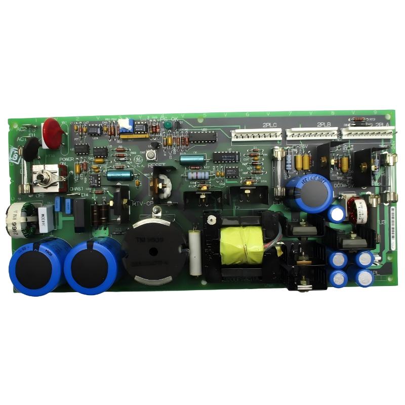
1. Product Overview
The GE DS200UPSAG1AGD is a UC2000 Power Supply Board designed for use in GE Speedtronic Mark V control systems. It carries the functional acronym UPSA and belongs to the DS200 family of industrial control circuit boards. The board is used in the power supply architecture of compatible turbine control equipment. It incorporates onboard power-related circuitry and supporting components, including protective fuses, capacitors, connectors, test points, a status LED, and a reset button. The DS200UPSAG1AGD is also associated with the EX2000 control system product family. Its role in an installed system should be confirmed from the cabinet drawings and original equipment configuration rather than inferred from the general Mark V product designation alone. Correct installation is important for maintaining stable control system operation. Engineers should verify the complete part number, board revision, connector arrangement, fuse specifications, and associated hardware before replacing or commissioning the board.
2. Technical Specifications
| Parameter | Specification |
|---|---|
| Manufacturer | General Electric (GE) |
| Model | DS200UPSAG1AGD |
| Product Type | UC2000 Power Supply Board |
| Functional Acronym | UPSA |
| Product Family | GE DS200 |
| Control System | GE Speedtronic Mark V |
| Related Product Family | EX2000 |
| Reset Button | 1 |
| Protective Fuses | 3 |
| Status Indicator | 1 LED |
| Connectors | 3 × 9-pin connectors |
| Other Components | Capacitors and test points |
| Associated Hardware | System-dependent; verify the installed configuration |
The exact electrical input range, output ratings, fuse ratings, and connector pin assignments should be confirmed using the correct GE documentation and the identification markings on the installed board. These values should not be assumed from specifications for other UPSA or DS200 power supply board revisions.
3. Main Functions and Board Components
3.1 Power Supply Function
The DS200UPSAG1AGD is identified as a UC2000 Power Supply Board. Its role is associated with the power supply arrangement of compatible GE control equipment. Power supply hardware is essential to industrial control systems because the associated electronic circuits require appropriate electrical power to operate. An abnormal supply condition can affect connected control equipment and may lead to system alarms or operational interruptions. The board must therefore be installed in the correct equipment configuration, with its electrical connections and protective components matching the approved design.
3.2 Three Protective Fuses
The board includes three fuses that provide circuit protection. These fuses are important during maintenance because an open fuse may interrupt an associated electrical path. However, a blown fuse can also indicate an underlying problem, such as a short circuit, damaged wiring, or a defective downstream component. Always verify the specified fuse type and rating before replacement. Never install a higher-rated fuse or bypass a protective device.
3.3 Status LED
The DS200UPSAG1AGD includes one LED indicator for visual status monitoring. The LED can provide useful information during installation and troubleshooting. Its exact operating indications should be interpreted using the applicable board documentation and system maintenance procedure. Do not assume that an illuminated LED proves that every power output or connected circuit is functioning correctly.
3.4 Reset Button
A reset button is provided on the board. It is intended for reset-related operations within the applicable hardware design. The reset button should not be used as a substitute for fault diagnosis. Before operating it, confirm the approved reset procedure and determine whether resetting the board could affect connected equipment or the turbine control system.
3.5 Three 9-Pin Connectors
The board contains three 9-pin connectors for its associated electrical and system interfaces. Connector assignments must be verified using the board markings, original wiring records, and the applicable Mark V or EX2000 drawings. Do not assume that connectors with the same physical format have identical electrical functions.
3.6 Capacitors and Test Points
The board contains multiple capacitors and designated test points. Capacitors may retain electrical energy after the equipment has been switched off. Test points provide access for authorized electrical checks, but their expected values and measurement procedures must be obtained from the correct documentation. Never assume that the board is safe to handle immediately after power isolation.
4. Preparation Before Installation
Proper preparation helps reduce the risk of installation errors and protects the control system from avoidable damage.
4.1 Verify the Complete Part Number
Confirm that the replacement board is marked: DS200UPSAG1AGD The complete suffix is important. Boards belonging to the same UPSA family may have different functional revisions, artwork revisions, or system applications. Do not select a replacement based only on the DS200UPSAG1 prefix.
4.2 Check the Physical Condition
Before installation, inspect the replacement board for:
- Cracks or damage to the PCB.
- Burn marks or discoloration.
- Damaged connector pins.
- Corrosion or contamination.
- Loose or damaged fuse holders.
- Leaking, swollen, or visibly damaged capacitors.
- Damaged reset button or LED components.
- Evidence of unauthorized repair or modification.
If the board shows signs of electrical or mechanical damage, do not install it until it has been evaluated by qualified personnel.
4.3 Record the Original Installation
When replacing an existing board, document its configuration before removal. Record:
- Complete board part number and revision markings.
- Installation location within the cabinet.
- All three 9-pin connector positions.
- Connector orientation and cable identification.
- Fuse markings and installed fuse types.
- LED condition before shutdown.
- Relevant system alarms.
- Any visible configuration differences.
Photographs and wiring records can help prevent connector interchange and incorrect installation.
4.4 Verify System Compatibility
Confirm that the DS200UPSAG1AGD is intended for the exact equipment position and control system configuration. Check the associated power supply arrangement, connected boards, wiring drawings, and cabinet documentation. The model number alone is not sufficient to establish compatibility with every Mark V or EX2000 installation.
5. Safety Precautions
The DS200UPSAG1AGD is an electronic power supply board. Its capacitors and connected circuits may retain hazardous electrical energy after the main power source has been disconnected. Before beginning installation:
- Follow the approved turbine or drive maintenance procedure.
- Shut down the affected equipment in the required sequence.
- Isolate all relevant power sources.
- Apply lockout/tagout procedures.
- Verify the absence of hazardous voltage using an appropriately rated instrument.
- Allow capacitors to discharge according to the applicable GE procedure.
- Use ESD protection when handling the PCB.
- Keep tools and loose metal objects away from exposed circuitry.
A waiting period alone does not prove that stored energy has been discharged. Always verify electrical safety before touching the board or its connected circuits. Do not remove or install the board while energized unless an explicitly approved procedure authorizes the operation and defines the necessary precautions.
6. DS200UPSAG1AGD Installation Procedure
6.1 Step 1: Shut Down and Isolate the Equipment
Place the affected turbine control or drive equipment in the approved maintenance condition. Isolate the relevant power sources and apply lockout/tagout requirements. Verify that the board and associated circuits are de-energized before proceeding. Pay particular attention to stored energy in onboard capacitors and connected power circuits.
6.2 Step 2: Document the Existing Board Connections
Before disconnecting the original board, record the position and identification of all three 9-pin connectors. Use clear photographs and cable labels to preserve the original arrangement. Do not rely on memory or connector appearance. Even when connectors are physically similar, their electrical functions may be different.
6.3 Step 3: Inspect the Fuse Arrangement
Check the three onboard fuses and their markings. If the replacement board is supplied with installed fuses, verify that their types and ratings match the approved specification for the exact board revision. Do not use fuse ratings from another UPSA board or from an online listing unless they are confirmed by the applicable technical documentation.
6.4 Step 4: Disconnect the Existing Board
After electrical isolation has been verified, disconnect the three 9-pin connectors carefully. Avoid pulling on the cable itself. Handle the connector housing and follow the correct release method for the installed connector type. Inspect each cable end for:
- Bent or damaged pins.
- Contamination.
- Loose contacts.
- Damaged insulation.
- Signs of overheating.
If a connector or cable is damaged, resolve the problem before installing the replacement board.
6.5 Step 5: Remove the Original Board
Release the board’s mounting hardware according to the cabinet assembly procedure. Support the PCB during removal to prevent bending or mechanical stress. Keep screws and other small hardware away from adjacent electronic assemblies. If the original board is being retained for repair or inspection, place it in ESD-protective packaging.
6.6 Step 6: Install the Replacement Board
Confirm the replacement board’s complete part number and revision before installation. Position the board in the designated mounting location and align its mounting points with the cabinet assembly. Secure the board using the specified hardware. Avoid excessive force and ensure that no cable or component is trapped beneath the PCB.
6.7 Step 7: Reconnect the Three 9-Pin Connectors
Reconnect each cable according to the labels, photographs, and approved system drawings. Before completing the connections, verify:
- Correct connector identification.
- Correct cable orientation.
- Proper alignment of the connector pins.
- Full connector engagement.
- No visible cable or contact damage.
Do not interchange connectors based on physical similarity. Incorrect connections may cause abnormal electrical behavior or prevent the associated system from operating correctly.
6.8 Step 8: Perform a Final Installation Inspection
Before restoring power, inspect the complete installation. Confirm that:
- The board is properly mounted.
- All three connectors are securely connected.
- The fuse arrangement matches the approved specification.
- No loose hardware remains in the cabinet.
- No cables are trapped or under mechanical strain.
- The board and surrounding assemblies show no visible damage.
7. Setup and Configuration Considerations
7.1 Power Supply Compatibility
The board must be used with the electrical supply arrangement specified for its intended equipment position. Before commissioning, verify the applicable input supply, output requirements, and connected load specifications using the correct system documentation. Do not use voltage or current values published for another DS200 power supply board as a substitute for the DS200UPSAG1AGD specification.
7.2 Fuse Configuration
The three onboard fuses must match the approved protection requirements. Check the fuse markings and the applicable parts documentation. If the fuse type or rating cannot be confirmed, do not energize the board until the correct information has been obtained. Repeated fuse failure should be investigated rather than addressed through repeated replacement.
7.3 Connector Configuration
The three 9-pin connectors must be connected according to the original system arrangement. Connector identification should be confirmed from board markings and the applicable wiring drawings. Do not infer pin assignments or electrical functions from connector position alone.
7.4 Reset Operation
The reset button should only be operated when required by the approved startup or maintenance procedure. Before resetting, review system alarms and determine whether the fault condition has been corrected. An unnecessary reset may interrupt normal operation or make fault diagnosis more difficult.
8. Commissioning and Functional Testing
Commissioning should confirm that the replacement board has been installed correctly and that the associated system operates normally.
8.1 Pre-Power Inspection
Before restoring power, check:
- Board part number and revision.
- Mounting security.
- Three connector positions.
- Fuse types and ratings.
- Visible component condition.
- Absence of loose hardware.
Any unexplained difference from the original installation should be resolved before proceeding.
8.2 Controlled Power Restoration
Restore power according to the approved equipment startup procedure. Observe the board and associated control system for abnormal conditions. Pay attention to unexpected alarms, unusual sounds, smoke, overheating, or abnormal electrical indications. If a fault is detected, stop the commissioning procedure and investigate its cause before continuing.
8.3 Check the LED Indicator
Observe the onboard LED during the approved startup sequence. Record whether it illuminates and compare its behavior with the documented status indication for the exact board revision. An illuminated LED should not be treated as proof that every output or connected power circuit is operating correctly. Continue with the required system-level checks.
8.4 Verify Power Circuit Conditions
Where the approved documentation provides test-point assignments and expected electrical values, qualified personnel may perform the specified measurements. For each measurement:
- Identify the correct test point from the board documentation.
- Confirm the expected voltage or electrical parameter.
- Select an appropriately rated measurement instrument.
- Follow the approved live-testing procedure, if applicable.
- Compare the measured result with the specified limits.
Do not probe unidentified test points or apply external voltage to them. Avoid using assumed electrical values from unrelated power supply boards.
8.5 Review Associated System Diagnostics
Review the relevant Mark V or EX2000 diagnostic information after power restoration. Confirm that the associated equipment reports normal operating status and that no new power-related alarms have appeared. If the system does not operate normally, investigate the upstream supply, board connections, fuses, and connected equipment before deciding that the replacement board is defective.
8.6 Confirm Stable Operation
After the initial checks are complete, follow the approved system procedure to confirm stable operation under the required operating conditions. The board should only be accepted after all required electrical and system-level checks have been completed.
9. Application Areas
The DS200UPSAG1AGD belongs to the GE Mark V DS200 product family and is identified as a UC2000 Power Supply Board. Its application should be determined from the installed control system architecture. Potential equipment contexts include:
- Gas Turbine Control: Power supply hardware within compatible GE turbine control arrangements.
- Steam Turbine Control: Electronic control equipment where the specific board configuration is approved.
- EX2000 Systems: Associated control system applications using compatible UPSA hardware.
- Industrial Power Generation: Power-related electronic assemblies used in turbine control cabinets.
The board should not be assumed to be suitable for every Mark V cabinet or EX2000 installation. Always confirm the exact equipment application and revision compatibility.
10. Maintenance Recommendations
A planned maintenance program can help identify deterioration before it affects equipment operation.
| Maintenance Area | Recommended Action | Purpose |
|---|---|---|
| PCB condition | Inspect for cracks, contamination, corrosion, and overheating | Identify physical deterioration |
| Three fuses | Inspect condition and verify approved ratings | Maintain correct circuit protection |
| LED indicator | Observe during scheduled system checks | Monitor the documented status indication |
| Reset button | Check physical condition and operation only under an approved procedure | Maintain reliable reset functionality |
| 9-pin connectors | Inspect contact condition and secure engagement | Prevent connection faults |
| Capacitors | Inspect for visible swelling, leakage, or damage | Identify component deterioration |
| Test points | Perform documented measurements when required | Support electrical condition assessment |
| System diagnostics | Review recurring power-related alarms | Identify developing system faults |
Maintenance intervals should be established according to equipment criticality, operating conditions, and the site’s approved maintenance schedule.
11. Frequently Asked Questions
What is the GE DS200UPSAG1AGD?
The DS200UPSAG1AGD is a GE UC2000 Power Supply Board with the functional acronym UPSA. It belongs to the DS200 product family and is associated with compatible Mark V and EX2000 control system applications.
How many fuses are installed on the board?
The board includes three protective fuses. Their exact types and ratings must be confirmed from the applicable board documentation and installed equipment requirements.
How many connectors does the DS200UPSAG1AGD have?
The board has three 9-pin connectors. Their electrical functions and pin assignments should be verified from the board markings and the relevant system drawings.
What is the function of the reset button?
The reset button provides a reset-related control function. It should only be operated according to the approved maintenance or startup procedure for the installed equipment.
What does the onboard LED indicate?
The LED provides a visual status indication. Its exact meaning should be checked against the documentation for the specific board revision. It should not be used as the only confirmation of power supply health.
How long should technicians wait after switching off the power?
Capacitors may retain electrical energy after shutdown. Follow the applicable discharge procedure and verify that hazardous residual voltage is absent before handling the board. A fixed waiting period alone is not sufficient to establish electrical safety.
Can the DS200UPSAG1AGD replace another UPSA board?
Not automatically. Replacement compatibility depends on the complete part number, functional and artwork revisions, connector arrangement, electrical specifications, and the intended Mark V or EX2000 equipment configuration.
What should be checked after installation?
Verify the board identification, mounting, three connector connections, fuse specifications, LED indication, documented test-point measurements, and associated system diagnostics before returning the equipment to service.
12. Conclusion
The GE DS200UPSAG1AGD UC2000 Power Supply Board is an electronic power-related component used in compatible GE Speedtronic Mark V control system applications. Its onboard fuses, LED indicator, reset button, capacitors, connectors, and test points support its role within the associated equipment architecture. Reliable installation requires accurate board identification, correct connector handling, verified fuse specifications, and careful attention to stored electrical energy. Commissioning should include visual inspection, controlled power restoration, documented electrical checks, and review of the associated system diagnostics. For industrial maintenance teams, following the correct board revision and equipment-specific documentation is essential for reducing installation errors and maintaining dependable turbine control operation.
Technical Summary
The GE DS200UPSAG1AGD is a UC2000 Power Supply Board carrying the UPSA functional acronym and belonging to the DS200 family. It is associated with GE Speedtronic Mark V and compatible EX2000 control system applications. The board includes three protective fuses, one LED indicator, one reset button, three 9-pin connectors, capacitors, and test points. Installation and commissioning must follow the exact equipment configuration and verified electrical documentation. Input ratings, output ratings, fuse values, and connector pin assignments should never be assumed from other board revisions.