
NewsNEWCENTER
Featured products

Contact Us
GE DS200TBQCG1ABB Analog I/O Termination Board: Troubleshooting, Fault Diagnosis and Repair Guide
2026-11-09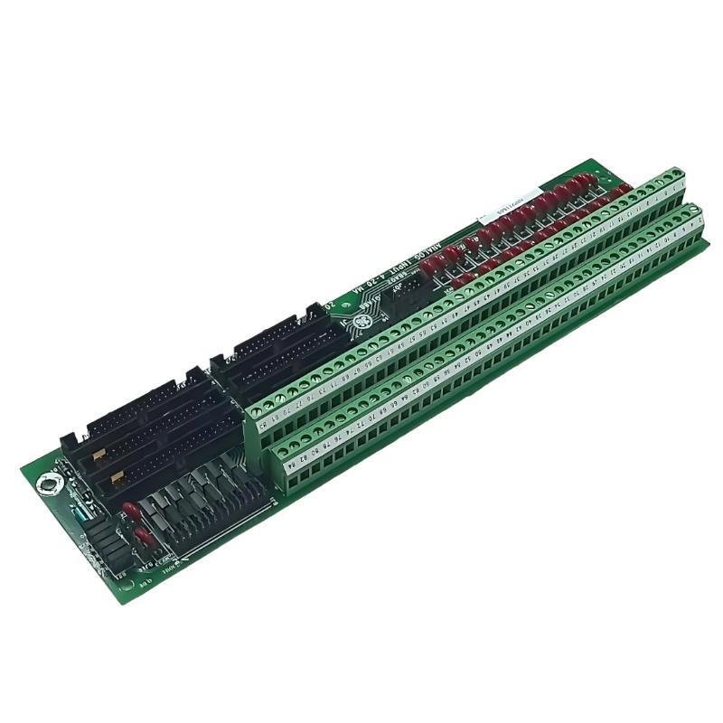
1. Introduction
The GE DS200TBQCG1ABB Analog Input Milliamp I/O Termination Module is part of the GE Mark V Speedtronic turbine control system. Also known as the RST Analog Termination Board, it provides termination and signal routing connections between field instrumentation and associated control electronics. The board is used in analog signal paths, including milliamp input/output circuits and LVDT/R position feedback connections. It works with associated TCQA control boards through dedicated ribbon-cable interfaces. Its terminal connections, jumpers, and connectors must therefore remain consistent with the installed Mark V system configuration. When problems occur, symptoms may include incorrect analog readings, missing input signals, abnormal milliamp outputs, unstable position feedback, or intermittent channel faults. These symptoms do not necessarily mean that the DS200TBQCG1ABB itself has failed. Field instruments, wiring, terminal connections, jumpers, ribbon cables, TCQA electronics, and software configuration can all contribute to similar problems. This guide explains how to diagnose common DS200TBQCG1ABB faults, isolate possible causes, inspect the board, and verify system operation after maintenance.
2. Product Identification and Main Features
Before troubleshooting, confirm the complete model number and hardware revision.
| Parameter | Specification |
|---|---|
| Manufacturer | General Electric (GE) |
| Model | DS200TBQCG1ABB |
| Product Type | Analog Input Milliamp I/O Termination Module |
| Functional Description | RST Analog Termination Board |
| Functional Acronym | TBQC |
| System | GE Mark V Speedtronic |
| Functional Revision | A / B |
| Artwork Revision | B |
| Terminal Blocks | 2 (TB1 and TB2) |
| Terminals | 83 per terminal block |
| Hardware Jumpers | 15, identified as BJ1 through BJ15 and BJ16/BJ17 output configuration positions |
| 40-Pin Connectors | 3 |
| 34-Pin Connectors | 3 |
| Associated Control Board | TCQA |
| Principal Interfaces | JBR, JFR, JBS/T, JFS/T and TEST |
The DS200TBQCG1ABB is a termination and interface board, not a standalone analog signal processor. Its performance depends on the complete signal path and the configuration of the associated Mark V control electronics.
3. Common Fault Symptoms
The following table summarizes typical symptoms that may occur in systems using the DS200TBQCG1ABB.
| Symptom | Possible Cause | Recommended Check |
|---|---|---|
| Analog input value is incorrect | Field transmitter fault, wiring problem, incorrect jumper configuration, or TCQA channel issue | Check field current, terminal connections, jumper settings, and channel diagnostics |
| Analog input remains fixed | Open circuit, short circuit, instrument failure, or incorrect signal routing | Inspect field wiring and compare the field signal with the control system indication |
| No milliamp output | Incorrect BJ16/BJ17 configuration, open load circuit, or TCQA output fault | Verify the documented output configuration and receiving circuit |
| Output current is inaccurate | Incorrect output range, load problem, wiring resistance, or control board fault | Check the configured current range and measure using an approved procedure |
| LVDT/R feedback is unstable | Sensor fault, damaged cable, loose JFR connection, or TCQA issue | Inspect the sensor circuit and connector interface |
| Multiple analog channels fail | Shared wiring, common signal reference, connector, or control electronics problem | Investigate common connections and associated TCQA hardware |
| Intermittent signal behavior | Loose terminals, damaged ribbon cable, contamination, or thermal-related connection problems | Inspect the complete signal path under safe maintenance conditions |
These symptoms are not definitive board fault codes. Diagnosis should establish whether the fault originates in the field device, termination board, control board, or system configuration.
4. Understanding the Main Connectors and Jumpers
Understanding the board’s connection arrangement is important before performing electrical checks.
4.1 JBR Connector
JBR is associated with the milliamp input and output signal interface between the TBQC termination board and the TCQA control board. The documented signal arrangement includes 4–20 mA input signals and milliamp output signals. A fault affecting multiple channels may justify inspecting this interface and the corresponding TCQA connection.
4.2 JFR Connector
JFR is associated with LVDT/R position input signals routed to the TCQA board. If position feedback is missing or unstable, inspect the field sensor circuit, its wiring, the JFR ribbon cable, and the associated TCQA circuitry.
4.3 JBS/T, JFS/T and TEST Connections
These connectors are identified on the board, but they are typically not used in normal operating configurations described for this board family. Do not connect test equipment or additional cables to them simply because a connector is available. Follow the exact Mark V system documentation.
4.4 Jumpers BJ1 Through BJ15
BJ1 through BJ15 are associated with milliamp input signal grounding or DCOM connection configuration. Their positions must match the approved system design. An incorrect jumper position may cause an input channel to behave differently from the intended configuration. Do not move a jumper as an experiment. Record the original configuration and verify the correct position using the applicable drawings and configuration records.
4.5 Jumpers BJ16 and BJ17
BJ16 and BJ17 are associated with the maximum current range selection for the two milliamp output circuits. The documented alternatives are 20 mA and 200 mA maximum output ranges. These settings are particularly important when diagnosing an output that is missing, limited, or inconsistent with the expected control signal. The correct position must be verified against the installed system configuration. Do not assume that both outputs use the same range.
5. Safety Precautions Before Troubleshooting
The DS200TBQCG1ABB is used in turbine control equipment. Incorrect electrical testing or configuration changes may affect process measurements, actuator control, or turbine protection functions. Before inspection or repair:
- Follow the approved turbine maintenance and isolation procedures.
- Apply lockout/tagout requirements to the relevant circuits.
- Verify electrical isolation before disconnecting field wires or ribbon cables.
- Use appropriate ESD protection when handling the PCB.
- Use properly rated and calibrated test instruments.
- Do not short adjacent terminals or connector pins.
- Do not change jumper settings without an approved configuration reference.
- Do not bypass control or protection functions to conceal a fault.
Some milliamp output configurations may have a maximum current range of 200 mA. Treat these circuits according to their documented electrical design. Do not assume that every output is a conventional low-current 4–20 mA loop. Live testing should only be performed by qualified personnel under an explicitly approved procedure that defines the permitted test points, instrument connections, and operational safeguards.
6. Step-by-Step Troubleshooting Procedure
6.1 Step 1: Identify the Affected Signal
Start by identifying the exact analog channel or position feedback circuit involved. Record:
- Field instrument tag number.
- Terminal block identification: TB1 or TB2.
- Terminal number.
- Signal type and expected operating range.
- Associated TCQA board and channel.
- Relevant Mark V alarms or diagnostic indications.
- Whether the fault is continuous or intermittent.
This information helps determine whether the problem is isolated to one field device or affects several channels sharing the same interface.
6.2 Step 2: Inspect Field Wiring and Terminal Connections
With the relevant circuits safely isolated, inspect the terminal connections. Check for:
- Loose terminal screws.
- Incorrect wire placement.
- Damaged conductor insulation.
- Corrosion or contamination.
- Broken or partially inserted conductors.
- Incorrect cable shielding or grounding.
- Signs of overheating around terminal contacts.
Verify every connection against the original wiring drawings. TB1 and TB2 terminal numbers must be treated separately. A wire connected to the wrong terminal can produce an incorrect process value even when the board itself is functioning normally.
6.3 Step 3: Check the Field Instrument Signal
For an analog input problem, verify whether the field instrument is producing the expected signal. Use the approved test procedure to assess the current signal at the designated measurement point. For a 4–20 mA input application, compare the measured current with the field instrument’s configured range and process conditions. If the field signal is already incorrect at the source, investigate the transmitter, instrument power supply, process connection, and field cable before replacing the TBQC board. If the field signal is correct but the control system value is wrong, continue checking the termination path, jumper configuration, ribbon cable, TCQA channel, and software scaling.
6.4 Step 4: Inspect BJ1 Through BJ15
If an input channel shows an abnormal value, inspect the associated input configuration jumpers. The BJ1–BJ15 group is associated with milliamp input signal connections to DCOM. Recommended procedure:
- Obtain the approved jumper configuration for the specific Mark V installation.
- Isolate the relevant equipment before handling the board.
- Record the existing jumper positions.
- Compare the physical configuration with the approved drawing.
- Check for missing, damaged, or incorrectly seated jumper caps.
- Correct discrepancies only under an authorized maintenance procedure.
Do not assume that every input channel uses the same grounding arrangement. The correct configuration depends on the actual system design.
6.5 Step 5: Inspect the JBR Ribbon Cable
If multiple milliamp channels show abnormal behavior, inspect the JBR interface. Check:
- Ribbon cable condition.
- Connector alignment.
- Contact contamination.
- Mechanical damage.
- Correct connection at both the TBQC and TCQA ends.
A damaged or incorrectly seated ribbon cable may affect more than one signal path. If the cable appears damaged, replace it only with the correct approved cable assembly.
6.6 Step 6: Diagnose the Milliamp Output Circuit
For a missing or inaccurate analog output, investigate the output configuration and the complete receiving circuit. Check:
- Whether the correct output channel is being commanded.
- Whether the receiving device and load circuit are connected correctly.
- Whether field wiring is open or damaged.
- Whether the output configuration matches the engineering records.
- Whether BJ16 and BJ17 are set to the required ranges.
- Whether the associated TCQA output channel is functioning correctly.
The output range selection is important because the board documentation identifies 20 mA and 200 mA maximum current configurations for the two milliamp outputs. Do not measure or simulate output current using an improvised connection. Follow the approved circuit-specific test procedure and use suitable instruments and test loads.
6.7 Step 7: Inspect the JFR Interface for LVDT/R Faults
If turbine valve or actuator position feedback is missing, unstable, or inconsistent, investigate the LVDT/R signal path. Check the following:
- Position sensor condition.
- Sensor cable continuity and insulation.
- Terminal assignments.
- Connector seating at JFR.
- Associated TCQA channel condition.
- System configuration and calibration records.
An LVDT/R feedback problem may originate from the sensor or its excitation and signal circuits rather than the TBQC termination board. Do not apply generic excitation voltage or frequency assumptions. Use the exact sensor and Mark V circuit documentation to establish the correct test values.
6.8 Step 8: Compare the Signal with TCQA Diagnostics
If the field signal is correct and the TBQC wiring appears normal, investigate the associated TCQA board. Compare the physical signal condition with the corresponding control system diagnostic information. A useful diagnostic sequence is:
- Verify the field signal at the approved measurement point.
- Confirm the TBQC terminal assignment.
- Check the relevant jumper configuration.
- Inspect the JBR or JFR interface as applicable.
- Review the corresponding TCQA channel diagnostics.
- Check the configured signal type and engineering range.
If the problem remains after the termination and cable checks, the TCQA input or output circuitry may require further evaluation.
7. Troubleshooting Specific Fault Conditions
7.1 Analog Input Value Is Fixed or Abnormal
A fixed or inaccurate analog value may be caused by:
- Failed field transmitter.
- Incorrect transmitter configuration.
- Open or shorted field wiring.
- Loose terminal connection.
- Incorrect BJ1–BJ15 configuration.
- Faulty JBR ribbon cable.
- TCQA channel malfunction.
- Incorrect software scaling or channel assignment.
Begin by checking the actual field current. If the signal is correct at the termination point, continue with the hardware interface and control system diagnostics.
7.2 No Milliamp Output Current
Possible causes include:
- Incorrect BJ16 or BJ17 output range configuration.
- Open receiving circuit.
- Incorrect field wiring.
- Receiving load outside the permitted circuit design.
- Missing or incorrect control command.
- Fault in the associated TCQA output channel.
Confirm the intended output range and receiving circuit design before performing current measurements. Do not change the jumper setting merely to see whether the output begins working.
7.3 Output Current Is Limited or Inaccurate
If an output cannot reach its expected value, compare the actual configuration with the control system design. Check the BJ16/BJ17 settings, output wiring, receiving equipment, and TCQA output channel. Also review whether the control system is commanding the expected value. A mismatch between the configured output range and the receiving circuit can create abnormal behavior or damage connected equipment.
7.4 LVDT/R Position Feedback Is Unstable
Position feedback instability may result from:
- Defective LVDT/R sensor.
- Damaged sensor cable.
- Loose terminal connection.
- Incorrect signal wiring.
- Poor JFR ribbon-cable connection.
- TCQA input circuit fault.
- Mechanical movement or linkage problems.
Compare electrical feedback with the actual mechanical position using the approved turbine maintenance procedure. Do not assume that every unstable feedback indication is caused by the termination board.
7.5 Several Analog Channels Fail at the Same Time
When multiple channels fail together, investigate shared components before replacing individual field instruments. Potential common causes include:
- Shared ribbon-cable connection.
- Common signal reference or grounding issue.
- Incorrect board configuration.
- TCQA interface fault.
- Shared field power or wiring problem.
A fault affecting several channels simultaneously is often a reason to examine common interfaces and system-level configuration.
7.6 Fault Returns After Board Replacement
If the same symptom appears after installing another DS200TBQCG1ABB, verify that the replacement procedure has reproduced the original system configuration. Check the complete part number, revision, terminal wiring, connector arrangement, jumper settings, and associated TCQA hardware. Also investigate whether an external fault remains in the field wiring, sensor, receiving load, or control system. Repeated board replacement without identifying the original cause may not resolve the problem.
8. Distinguishing a TBQC Fault from a TCQA or Field Device Fault
A systematic comparison can help identify which part of the signal path is responsible.
| Observed Condition | Likely Area to Investigate |
|---|---|
| Field instrument output is incorrect | Field instrument, instrument power, process connection |
| Field signal is correct at the source but incorrect at the TBQC terminal | Field cable, terminal connection, wiring assignment |
| Signal reaches the TBQC correctly but control indication is abnormal | Jumper configuration, JBR/JFR interface, TCQA channel, software configuration |
| Several channels associated with one interface fail | Ribbon cable, common connection, TCQA interface |
| Only one output channel fails | Output configuration, field load, wiring, or individual TCQA output circuit |
| Position feedback disagrees with actual mechanical position | LVDT/R sensor, mechanical linkage, wiring, JFR interface, TCQA circuitry |
This comparison is a diagnostic aid, not a substitute for the official Mark V troubleshooting procedure.
9. Board Inspection, Repair and Replacement
9.1 Visual Inspection
After the board has been safely isolated and removed where necessary, inspect:
- PCB surfaces for cracks or damaged tracks.
- Terminal blocks for heat damage.
- Ribbon-cable connectors for damaged contacts.
- Jumper headers for mechanical damage.
- Solder joints for visible cracking.
- Areas affected by corrosion or contamination.
Do not return a visibly damaged board to service without proper evaluation.
9.2 Repair Considerations
The DS200TBQCG1ABB contains multiple signal interfaces and configuration components. Component-level repair should be performed only by qualified electronic repair specialists. Any repair should preserve the original circuit design and be followed by suitable inspection and functional testing. Unauthorized jumper modifications, PCB track changes, or substitute components can affect signal integrity and system reliability.
9.3 Replacement Procedure
If the board is confirmed defective:
- Confirm the complete replacement part number and revision.
- Record all terminal connections and connector positions.
- Photograph and document the original jumper configuration.
- Isolate the equipment and remove the original board safely.
- Inspect the replacement board before installation.
- Install the replacement in the approved location.
- Reconnect the ribbon cables and field wiring according to the drawings.
- Verify jumper settings against the original approved configuration.
- Perform controlled restoration and commissioning checks.
Do not assume that another TBQC model or a board with a similar appearance is automatically compatible.
10. Preventive Maintenance Recommendations
Regular inspection and accurate configuration records help reduce recurring analog signal faults.
| Inspection Area | Recommended Action | Purpose |
|---|---|---|
| Terminal blocks | Inspect connections and wiring condition | Prevent loose or incorrect field connections |
| Ribbon cables | Inspect connector seating and cable condition | Maintain reliable signal routing |
| BJ1–BJ15 | Compare positions with approved configuration records | Maintain correct input signal configuration |
| BJ16 and BJ17 | Verify output range selection | Prevent output range mismatch |
| Field instruments | Review calibration and signal condition | Maintain accurate process measurements |
| TCQA interface | Review channel diagnostics | Identify associated control board faults |
| PCB condition | Inspect for corrosion, contamination, and overheating | Identify physical deterioration |
| Maintenance records | Update wiring, jumper, and replacement records | Improve future troubleshooting accuracy |
Inspection intervals should follow the site’s turbine maintenance plan and equipment criticality requirements.
11. Frequently Asked Questions
What are the common faults associated with the DS200TBQCG1ABB?
Common problems include abnormal milliamp input readings, missing output current, incorrect output ranges, unstable LVDT/R feedback, loose terminal connections, and ribbon-cable interface faults. The source may be the board, field wiring, instruments, or associated TCQA electronics.
What is the function of BJ1 through BJ15?
BJ1 through BJ15 are associated with milliamp input signal connections to DCOM. Their correct positions depend on the installed Mark V configuration and should be verified against the approved drawings.
What do BJ16 and BJ17 control?
BJ16 and BJ17 are associated with the maximum current range selection for the two milliamp output circuits. The documented alternatives are 20 mA and 200 mA maximum ranges. Always confirm the required configuration before changing either jumper.
What should be checked when a 4–20 mA input is incorrect?
Check the field instrument, actual signal current, field cable, terminal assignment, BJ1–BJ15 configuration, JBR connection, associated TCQA channel, and software scaling. Follow the signal path systematically rather than immediately replacing the termination board.
Why is there no milliamp output?
Possible causes include an incorrect output range configuration, an open load circuit, wiring problems, an absent control command, or a fault in the associated TCQA output circuitry.
What causes unstable LVDT/R feedback?
Potential causes include a faulty position sensor, damaged cable, incorrect wiring, poor JFR connector contact, TCQA input problems, or mechanical linkage issues. The complete sensor-to-controller signal path should be inspected.
Can the DS200TBQCG1ABB be replaced by another TBQC board?
Not without compatibility verification. Confirm the full part number, hardware revision, terminal arrangement, connector configuration, jumper positions, associated TCQA hardware, and the Mark V system requirements.
Should all connectors on the board be used?
No. The board has several connector positions, but JBS/T, JFS/T, and TEST are typically unused in the normal operating arrangements described for this board family. Follow the specific system drawings rather than connecting every available interface.
12. Conclusion
The GE DS200TBQCG1ABB Analog I/O Termination Board is an important signal interface component in the Mark V Speedtronic turbine control system. Its two terminal blocks, ribbon-cable interfaces, and hardware jumpers support milliamp analog signals and LVDT/R position feedback connections. Effective troubleshooting requires a complete understanding of the signal path. Engineers should verify field instrument signals, terminal wiring, BJ1–BJ15 input configuration, BJ16/BJ17 output range settings, JBR and JFR connections, and the associated TCQA control electronics. By following a systematic diagnostic process and preserving the approved hardware configuration, maintenance teams can identify the actual source of signal faults, reduce unnecessary board replacement, and support reliable turbine control operation.
Technical Summary
The GE DS200TBQCG1ABB is an RST Analog Termination Board used in the GE Mark V Speedtronic control system. It provides termination and interface connections for milliamp analog signals and LVDT/R position feedback. Troubleshooting should focus on TB1/TB2 field wiring, BJ1–BJ15 input configuration, BJ16/BJ17 output range selection, JBR/JFR ribbon-cable connections, and the associated TCQA circuitry. Always verify the exact board revision and approved system configuration before making wiring or jumper changes.