

ProductPRODUCT
Featured products
Contact Us
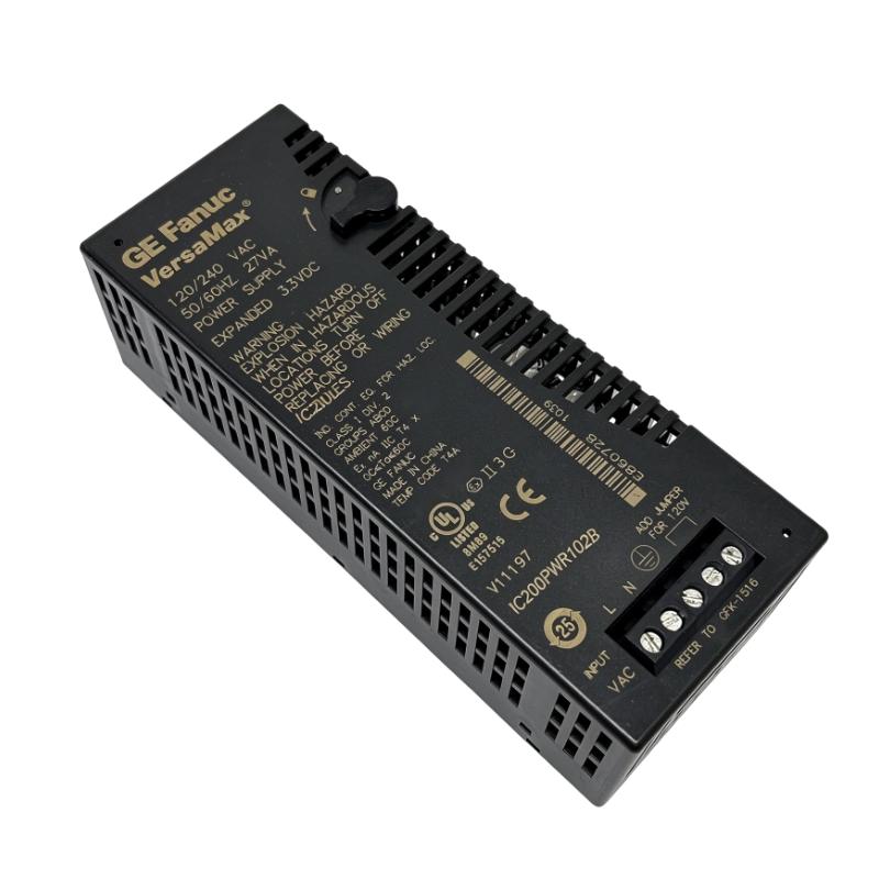
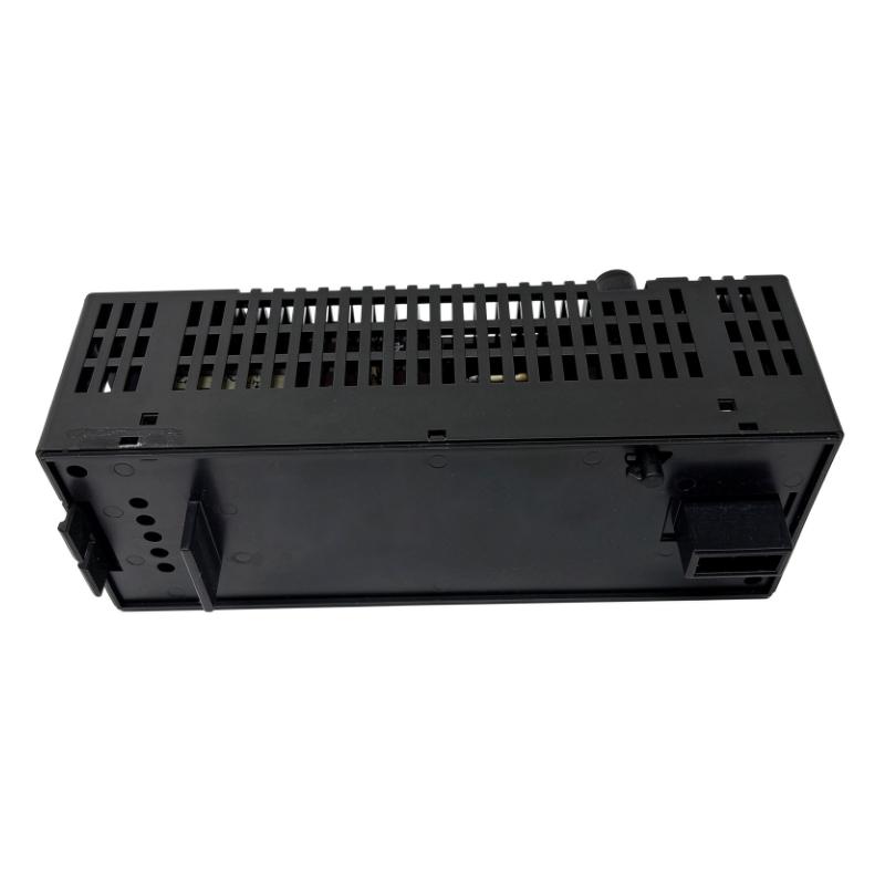
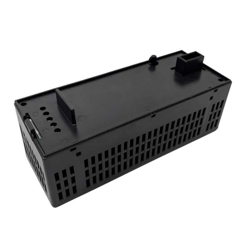
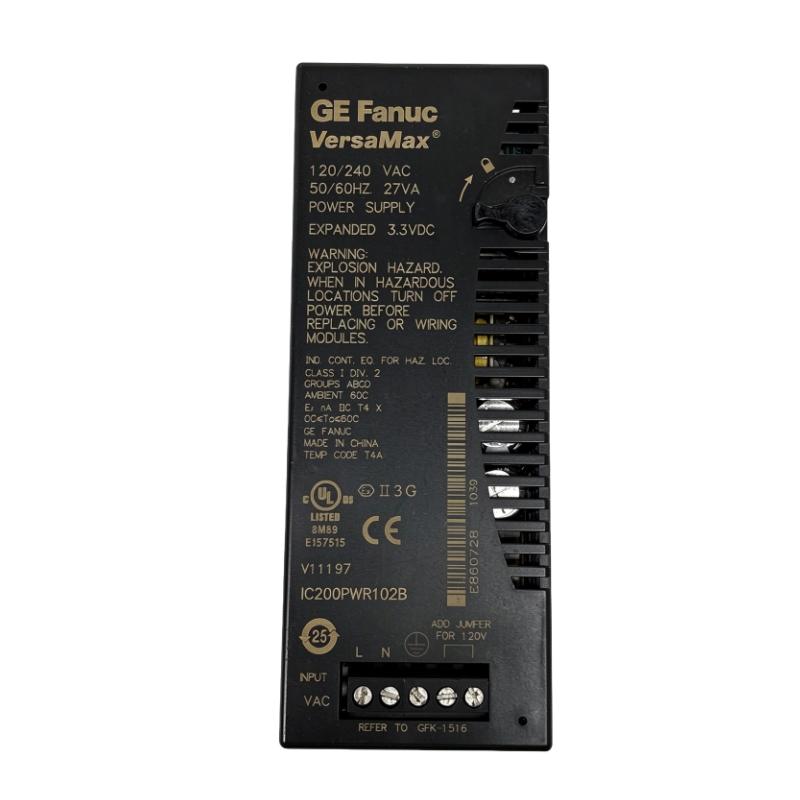
- GE
- IC200PWR102B
- VersaMax Power Module
- USA
- 133.4 x 39 x 49 mm
- 0.118 kg
- Xiamen, China
- New & In Stock
- T/T, PayPal, Western Union
- 1 Year
- 1-3 Working Days
- DHL, UPS, TNT, FedEx and EMS.
- 24-Hour Service
- COO
- 5
Our advantage

Global Logistics
We have a 10-year logistics and express cooperation agreement, so our products can be shipped to any place in the world.

Brand new and original
Our products are imported in bulk from the place of origin. Because of the cooperative relationship, our products are all original and 100% new.

24-hour service
We provide 7*24 hours service to our customers. We will be there whenever you need us.

Price advantage
All our products are priced very favorably because we have our own warehouse and supply.
| Company Information | |||
| [email protected] | |||
| Mobile | +8615980777398 | ||
| +8615980777398 | |||
| 15980777398 |
Product Overview
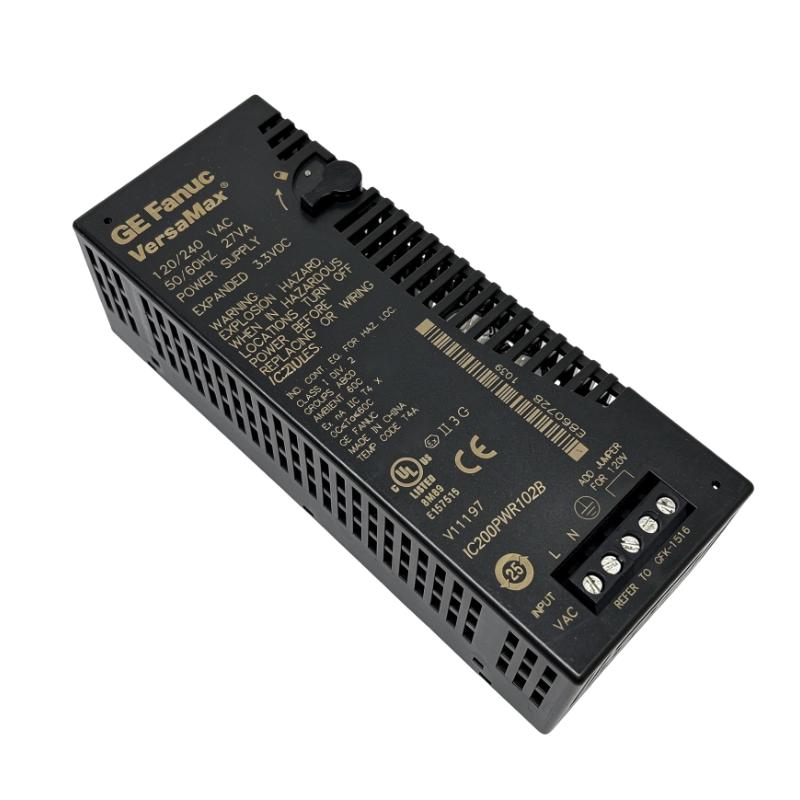
The GE IC200PWR102B VersaMax Power Module is an AC-powered supply module designed for GE Fanuc VersaMax programmable logic controller (PLC) and distributed I/O systems. It provides the DC power required by the controller station’s backplane, supporting the operation of compatible CPU, network interface, and I/O modules.
As part of the IC200PWR102 power supply family, the IC200PWR102B supports both 120 V AC and 240 V AC nominal input operation. It provides 5 V DC and 3.3 V DC outputs, with a combined maximum output current of 1.5 A. Its expanded 3.3 V DC output capability makes it suitable for VersaMax configurations that require power for modules using this voltage.
The module can serve as the primary power supply when mounted on a compatible VersaMax CPU or Network Interface Unit (NIU). It can also be used as a supplemental power source when installed on a compatible power supply booster carrier. This flexibility allows system designers to distribute power across larger I/O configurations where the current requirements exceed the capacity of a single supply.
The IC200PWR102B is designed for industrial control cabinets and modular automation installations. Its compact form factor supports installation in VersaMax systems where available mounting space is limited.
When replacing an existing unit, users should verify the complete model number and revision, input-voltage selection, output-current requirements, and mounting arrangement. Although different IC200PWR102 revisions may share similar electrical specifications, the actual hardware revision and system compatibility should be confirmed before installation.
Technical Specifications
| Parameter | Specification |
|---|---|
| Brand | GE Fanuc / GE Intelligent Platforms |
| Product Family | VersaMax |
| Model | IC200PWR102B |
| Product Type | AC Power Supply Module |
| Module Series | IC200PWR102 |
| Input Voltage | 120/240 V AC nominal |
| Input Voltage Range | 85–132 V AC with jumper; 176–264 V AC without jumper |
| Input Frequency | 47–63 Hz |
| Input Power | 27 VA |
| Output Voltage | 5 V DC and 3.3 V DC |
| Total Output Current | 1.5 A maximum |
| Maximum 3.3 V DC Output Current | 1.0 A |
| 5 V DC Output Current | Up to 1.5 A minus the 3.3 V DC current used |
| Hold-Up Time | 20 ms |
| Protection | Short-circuit and overload protection |
| Voltage Selection | Jumper configuration |
| Mounting | Compatible VersaMax CPU, NIU, or power supply booster carrier |
| Dimensions Provided | 133.4 × 39 × 49 mm |
| Weight Provided | 0.118 kg |
| Typical Application | VersaMax PLC and distributed I/O power supply |
Note: The supplied dimensions are retained as listing specifications. Manufacturer documentation presents the dimensional order as width × height × depth. The module’s mounting carrier and DIN rail are not included in the module dimensions.
Function and Working Principle
The primary function of the IC200PWR102B is to convert incoming AC electrical power into regulated DC power for a VersaMax control station.
Industrial PLC systems contain electronic components that require stable low-voltage DC power. The power supply module provides these voltages through the system’s backplane, allowing compatible controller and I/O modules to operate.
1. AC Input Power Conversion
The IC200PWR102B accepts either 120 V AC or 240 V AC nominal input power. The supported input range depends on the voltage-selection jumper configuration.
For 120 V AC nominal operation, the jumper must be installed as specified by the manufacturer. For 240 V AC nominal operation, the jumper must be removed.
This configuration is important because the module’s input selection is not simply an automatic voltage adjustment. Incorrect jumper placement can damage the power supply and create hazardous conditions.
2. 5 V DC Power Output
The 5 V DC output supplies compatible electronic circuits in the VersaMax station. Depending on the system configuration, this voltage supports the backplane power requirements of installed controller and I/O components.
The available 5 V DC current is affected by the amount of current used by the 3.3 V DC output. The combined output current must remain within the module’s maximum rating of 1.5 A.
3. Expanded 3.3 V DC Power Output
One of the defining characteristics of the IC200PWR102B is its expanded 3.3 V DC output capability.
The module can supply up to 1.0 A on the 3.3 V DC output. This is relevant to VersaMax system configurations containing modules that require this voltage.
The 3.3 V DC and 5 V DC outputs share the same total current limit. For example, if the 3.3 V DC output supplies 1.0 A, the remaining available current for the 5 V DC output is limited to 0.5 A.
4. Hold-Up Time
The documented hold-up time is 20 milliseconds. Hold-up time describes how long the power supply can maintain its output after a brief interruption of the input supply, under the specified operating conditions.
This function can help the control station tolerate short power disturbances. It does not replace an uninterruptible power supply or guarantee continued operation during extended power failures.
5. Protection Functions
The module includes short-circuit and overload protection. These functions help protect the power supply when output conditions exceed normal operating limits.
Correct load calculation, wiring, and module installation remain necessary. Protection features should not be treated as substitutes for proper system design or upstream electrical protection.
Role in VersaMax PLC Systems
The IC200PWR102B is an important component in a VersaMax automation station because it supplies the DC power required by the controller and associated modules.
Powering the Controller Station
A VersaMax PLC installation may contain a CPU, I/O modules, and a network interface unit. These devices depend on the station’s power supply to operate.
The IC200PWR102B can be mounted directly on a compatible CPU or NIU to provide the primary station power source. Its output supports the electronic circuits connected to the system backplane.
Supporting Distributed I/O
Distributed I/O systems allow input and output devices to be located closer to field equipment rather than being concentrated in one control cabinet.
The IC200PWR102B can provide power to a VersaMax station containing compatible I/O modules. The actual number of modules supported depends on their current consumption and the available power budget.
Expanding System Power Capacity
Larger I/O installations may require additional power capacity. The IC200PWR102B can also be used as a supplemental power supply when mounted on a compatible VersaMax power supply booster carrier.
This arrangement allows additional power to be supplied to modules in an expanded station. Engineers must calculate the power requirements of the modules and follow the manufacturer’s booster-carrier installation guidelines.
Supporting Stable PLC Operation
A stable DC supply is essential for reliable controller operation. Voltage fluctuations, excessive loading, incorrect input selection, or poor electrical connections can lead to abnormal operation or unexpected shutdowns.
Using a correctly configured power supply helps maintain the electrical conditions required by the VersaMax controller station.
Industrial Applications
The IC200PWR102B is intended for VersaMax PLC and distributed I/O installations in industrial automation environments.
1. Manufacturing Automation
Manufacturing systems use PLCs to coordinate machines, monitor production conditions, and control equipment sequences.
The IC200PWR102B provides backplane power for compatible VersaMax controller and I/O modules. It can therefore form part of the electrical infrastructure supporting automated production equipment.
2. Process Control Systems
Industrial process-control installations use sensors, actuators, and control logic to monitor and regulate production operations.
A VersaMax station may collect field signals and exchange control information with other system components. The IC200PWR102B supplies the DC power required by compatible modules within that station.
3. Distributed I/O Cabinets
Large facilities often use multiple remote I/O stations to connect field devices in different areas of a plant.
The IC200PWR102B can serve as the power source for a compatible VersaMax I/O station. Its expanded 3.3 V DC output supports configurations with modules requiring that voltage.
4. Packaging and Material Handling
Packaging lines and material-handling systems use PLCs to coordinate conveyors, sensors, motors, and pneumatic equipment.
Where VersaMax controllers are installed, the IC200PWR102B can supply the station’s backplane power and support the operation of connected control modules.
5. Water and Utility Automation
Water treatment facilities, pumping stations, and utility installations may use PLC-based monitoring and control systems.
A VersaMax PLC station can manage signals from field instruments and coordinate equipment operation. The IC200PWR102B supplies the DC power required by compatible modules in the station.
6. Industrial Equipment Maintenance
The IC200PWR102B may also be required in maintenance and spare-parts programs for existing VersaMax installations.
Keeping a correctly specified replacement available can help maintenance teams restore a controller station when its original power supply fails.
Installation and System Integration
Correct installation is essential for the safe and reliable operation of the IC200PWR102B.
1. Verify the Input Voltage
Before applying power, identify the available AC supply voltage.
The module supports:
- 120 V AC nominal input with the specified jumper installed.
- 240 V AC nominal input with the jumper removed.
Never install the 120 V selection jumper when operating the module from a 240 V AC supply. Incorrect configuration can damage the unit and create hazardous conditions.
Always verify the actual module markings and manufacturer installation instructions before energizing the equipment.
2. Confirm Output Power Requirements
Calculate the combined current requirements of the VersaMax modules connected to the power supply.
The total output current must not exceed 1.5 A. The 3.3 V DC output can supply up to 1.0 A, while the available 5 V DC current is reduced by the amount used on the 3.3 V DC output.
For example:
| 3.3 V DC Current Used | Maximum Remaining 5 V DC Current |
|---|---|
| 0.0 A | 1.5 A |
| 0.25 A | 1.25 A |
| 0.5 A | 1.0 A |
| 0.75 A | 0.75 A |
| 1.0 A | 0.5 A |
These values illustrate the shared output-current limit. Actual system loading should be calculated using the current-consumption specifications of every installed module.
3. Mounting and Mechanical Installation
The supplied module dimensions are 133.4 × 39 × 49 mm. The module is designed for compatible VersaMax mounting arrangements.
It can be installed on a supported CPU or NIU as a main power supply, or on a compatible power supply booster carrier for supplemental power applications.
Ensure that the mounting surface, carrier, and DIN rail are correctly installed. Allow adequate space for wiring and maintenance access.
4. Wiring and Grounding
Connect the AC input according to the module’s terminal markings and installation documentation.
Verify line, neutral, and protective grounding connections before energizing the unit. Use appropriately rated conductors and follow applicable electrical safety regulations.
Power wiring should be protected against accidental contact and mechanical damage. All installation and maintenance work should be performed by qualified personnel with the equipment isolated from hazardous electrical sources.
5. System Startup and Testing
After installation, verify the input-voltage selection and inspect all electrical connections.
Energize the power supply according to the commissioning procedure. Confirm that the VersaMax station starts correctly and that the installed CPU, NIU, and I/O modules operate normally.
If the station experiences unexpected resets, module faults, or power-related alarms, check the input supply, jumper configuration, output loading, wiring, and condition of the power supply.
Compatible System Components
The IC200PWR102B is designed to operate within a compatible VersaMax modular automation system.
| Component | Function | Integration Considerations |
|---|---|---|
| VersaMax CPU | Executes PLC logic and controls the automation process | Verify CPU model and power requirements |
| VersaMax Network Interface Unit | Connects a distributed I/O station to the control network | Confirm compatible power supply mounting |
| VersaMax I/O Modules | Receive field signals and control output devices | Calculate the combined backplane current requirement |
| VersaMax Power Supply Booster Carrier | Supports supplemental power distribution | Requires a compatible power supply module |
| DIN Rail | Provides mechanical mounting for the system | Verify rail installation and mechanical stability |
| Industrial AC Supply | Provides the power input to the module | Configure for 120 V or 240 V AC correctly |
| Field Sensors | Provide process measurement signals | Connected through compatible input modules |
| Actuators and Control Devices | Execute commands from the PLC system | Connected through compatible output modules |
| Industrial Control Cabinet | Houses and protects the PLC equipment | Provide suitable environmental protection and ventilation |
The components listed above are examples of equipment used in a VersaMax installation. They are not necessarily included with the IC200PWR102B.
Alternative Models and Replacement Considerations
When replacing an IC200PWR102B, the complete model number and electrical specifications should be checked.
| Model | Description | Main Difference |
|---|---|---|
| IC200PWR102 | VersaMax 120/240 V AC power supply with expanded 3.3 V DC output | Base model designation |
| IC200PWR102A | IC200PWR102 family revision | Verify hardware revision and system requirements |
| IC200PWR102B | VersaMax 120/240 V AC power supply, revision B | Exact model covered in this article |
| IC200PWR102C and later revisions | Later IC200PWR102 family revisions | Confirm revision-specific compatibility |
| IC200PWR201 | VersaMax 12 V DC power supply | Uses DC input rather than AC input |
| IC200PWR202 | VersaMax 12 V DC power supply with expanded 3.3 V DC output | Different input-power arrangement |
A related model should not automatically be treated as a direct replacement. Before substitution, compare:
- Input voltage and voltage-selection requirements.
- Output voltage and total output current.
- 3.3 V DC output capacity.
- Mounting and carrier compatibility.
- Hardware revision and system documentation.
- Installed module current consumption.
- Required primary or supplemental power arrangement.
For maintenance projects, matching the original IC200PWR102B revision is generally the simplest way to reduce configuration uncertainty. If a different revision or model is selected, verify compatibility with the installed VersaMax hardware.
Key Advantages
Dual AC Input Selection
The module supports both 120 V AC and 240 V AC nominal input operation, allowing it to be used with different industrial AC supply arrangements when correctly configured.
Expanded 3.3 V DC Output
The expanded 3.3 V DC output supports VersaMax system configurations that require additional power at this voltage.
Combined 5 V DC and 3.3 V DC Outputs
The module supplies two DC output voltages through a single power supply unit, supporting compatible controller and I/O electronics.
Flexible Mounting Arrangement
It can be used as a primary power source on a compatible CPU or NIU, or as a supplemental supply on a power supply booster carrier.
Short-Circuit and Overload Protection
Built-in protection functions help protect the power supply against specified abnormal output conditions.
Compact Installation
The module’s compact dimensions support installation in modular VersaMax control systems and industrial cabinets.
Established VersaMax Compatibility
The IC200PWR102B is designed for the VersaMax automation platform, making it relevant to maintenance and spare-parts requirements for existing installations.
Technical FAQs
1. What is the GE IC200PWR102B?
The GE IC200PWR102B is a VersaMax AC power supply module. It converts incoming AC power into 5 V DC and 3.3 V DC outputs for compatible PLC and distributed I/O station components.
2. What input voltage does the IC200PWR102B support?
It supports 120 V AC and 240 V AC nominal input. The specified input ranges are 85–132 V AC with the jumper installed and 176–264 V AC without the jumper.
3. What is the output voltage?
The module provides 5 V DC and 3.3 V DC outputs. These outputs supply power to compatible VersaMax backplane components.
4. What is the maximum output current?
The combined maximum output current is 1.5 A. The 3.3 V DC output can provide up to 1.0 A, and the available 5 V DC current depends on the current consumed by the 3.3 V DC output.
5. Can the IC200PWR102B operate at both 120 V and 240 V AC?
Yes, but the voltage-selection jumper must be configured correctly. Install the jumper for 120 V AC nominal operation and remove it for 240 V AC nominal operation.
6. Can this module be used as a supplemental power supply?
Yes. It can be mounted on a compatible VersaMax power supply booster carrier and used as a supplemental power source for an expanded I/O installation.
7. Does the module include overload protection?
Yes. The documented protection functions include short-circuit and overload protection.
8. What is the hold-up time?
The specified hold-up time is 20 milliseconds under the manufacturer’s stated operating conditions.
9. Is IC200PWR102B compatible with all VersaMax I/O modules?
Not automatically. Compatibility depends on the mounting arrangement and the power requirements of the installed modules. The combined current consumption must remain within the power supply’s output limits.
10. What should be checked before purchasing a replacement?
Verify the complete model number, revision, input-voltage configuration, output ratings, physical condition, and compatibility with the installed CPU, NIU, and I/O modules.
Procurement and Maintenance Recommendations
When purchasing the GE IC200PWR102B, confirm that the product label matches the required catalog number and revision. The IC200PWR102 family includes different hardware revisions, so checking only the base model number may not be sufficient for every replacement project.
For new, surplus, or refurbished units, request clear photographs of the front label, terminal area, and overall module condition. Confirm whether the module has been tested and whether any warranty or return conditions apply.
Before installation, calculate the power consumption of the complete VersaMax station. Ensure that the combined 5 V DC and 3.3 V DC current remains within the module’s 1.5 A maximum rating.
During maintenance, inspect the AC input wiring, voltage-selection jumper, grounding connection, mounting carrier, and module terminals. Check for signs of overheating, loose connections, or physical damage.
It is also advisable to keep a record of the installed module revision and the power requirements of the connected I/O modules. This information can simplify future troubleshooting and help maintenance teams identify a suitable replacement.
Conclusion
The GE IC200PWR102B VersaMax Power Module is a compact AC power supply designed for compatible VersaMax PLC and distributed I/O systems. It accepts 120 V AC or 240 V AC nominal input, depending on the jumper configuration, and provides 5 V DC and 3.3 V DC outputs with a combined maximum current of 1.5 A.
Its expanded 3.3 V DC output, flexible mounting arrangement, and short-circuit and overload protection make it a useful power component in VersaMax automation installations. For replacement and maintenance applications, correct input-voltage selection, output-load calculation, and hardware revision verification are essential for reliable operation.