

ProductPRODUCT
Featured products
Contact Us
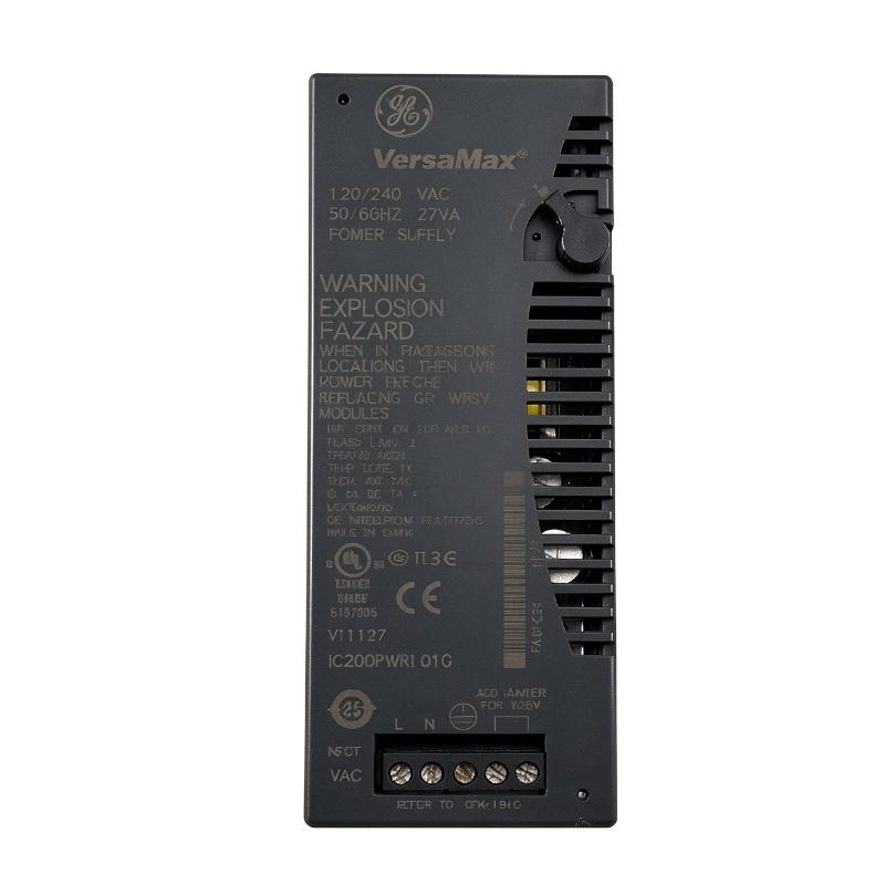
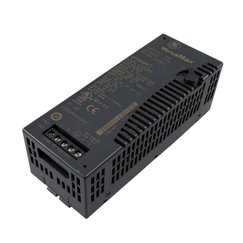
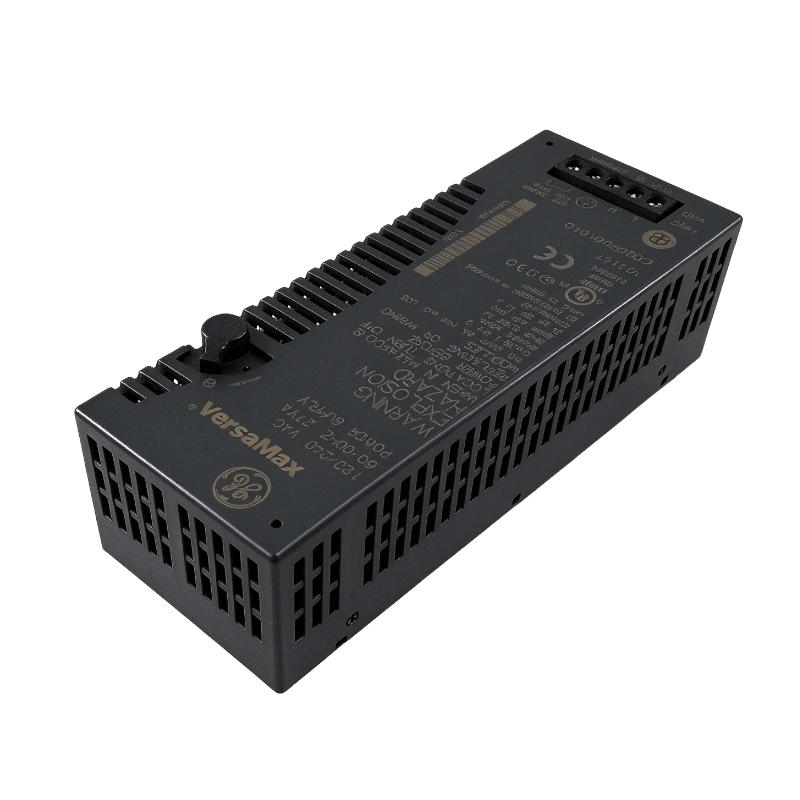
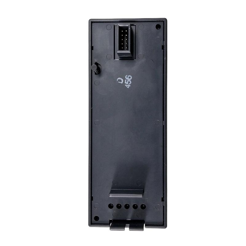
- GE
- IC200PWR101G
- VersaMax Power Module
- USA
- 133.4 x 39 x 49 mm
- 0.25 kg
- Xiamen, China
- New & In Stock
- T/T, PayPal, Western Union
- 1 Year
- 1-3 Working Days
- DHL, UPS, TNT, FedEx and EMS.
- 24-Hour Service
- COO
- 5
Our advantage

Global Logistics
We have a 10-year logistics and express cooperation agreement, so our products can be shipped to any place in the world.

Brand new and original
Our products are imported in bulk from the place of origin. Because of the cooperative relationship, our products are all original and 100% new.

24-hour service
We provide 7*24 hours service to our customers. We will be there whenever you need us.

Price advantage
All our products are priced very favorably because we have our own warehouse and supply.
| Company Information | |||
| [email protected] | |||
| Mobile | +8615980777398 | ||
| +8615980777398 | |||
| 15980777398 |
Product Overview
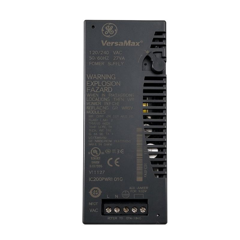
The GE IC200PWR101G VersaMax Power Module is an AC-input power supply designed for GE Fanuc VersaMax programmable logic controller systems. It provides regulated DC power to the internal backplane of a VersaMax control station, supporting the operation of CPUs, network interface units, and input/output modules.
In an industrial automation system, a stable power supply is essential for reliable PLC operation. The power module converts incoming AC electrical power into the DC voltages required by the control system. These voltages are distributed through the backplane to compatible modules installed in the station.
The IC200PWR101G supports 120 V AC and 240 V AC nominal input configurations. Its input range is selected through the appropriate jumper arrangement. The module provides 5 V DC and 3.3 V DC outputs, with a maximum combined output current of 1.5 A. The 3.3 V DC output supports up to 0.25 A, while the available 5 V DC current depends on the current consumed by the 3.3 V output.
The module can serve as the primary power source when mounted on a compatible VersaMax CPU or network interface unit. It can also function as a supplemental power source when installed on a suitable power supply booster carrier.
The IC200PWR101G is designed for VersaMax distributed I/O and PLC applications where an AC-powered backplane supply is required. Its compact form supports installation in industrial control cabinets and distributed automation stations.
Technical Specifications
| Parameter | Specification |
|---|---|
| Brand | GE Fanuc / GE |
| Product Series | VersaMax |
| Model | IC200PWR101G |
| Product Type | AC Power Supply Module |
| Input Voltage | 120/240 V AC nominal |
| Input Voltage Range | 85–132 V AC with 120 V jumper setting; 176–264 V AC without jumper |
| Input Power | 27 VA |
| Input Frequency | 47–63 Hz |
| Output Voltage | 5 V DC and 3.3 V DC |
| Total Output Current | 1.5 A maximum |
| 3.3 V DC Output Current | 0.25 A maximum |
| 5 V DC Output Current | 1.5 A minus the current used by the 3.3 V output |
| Hold-Up Time | 20 ms |
| Protection | Short-circuit and overload protection |
| Extended Power | Not supported |
| Typical Mounting | Compatible VersaMax CPU, NIU, or power supply booster carrier |
| Dimensions Provided | 133.4 × 39 × 49 mm |
| Weight Provided | 0.25 kg |
| Application | VersaMax PLC and distributed I/O power supply |
Note: The dimensions and weight above are the supplied product-listing values. Manufacturer dimensional data may use a different measurement orientation and may exclude the carrier or DIN rail.
Function and Working Principle
The IC200PWR101G supplies the DC power required by VersaMax control-system modules. It receives AC input power, converts it into regulated DC outputs, and distributes those outputs to compatible components through the system backplane.
1. AC-to-DC Power Conversion
The module accepts AC electrical power from an industrial control cabinet supply. Its internal power-conversion circuitry generates the DC voltage levels required by the VersaMax backplane.
The two output voltages serve different electronic power requirements within the control station. The 5 V DC and 3.3 V DC supplies support compatible CPUs, communication interfaces, and I/O modules.
Stable output power is important because PLC processing, communication, and I/O operations depend on reliable electronic supply conditions.
2. Dual-Voltage Output
The IC200PWR101G provides two DC output levels:
- 5 V DC: Supplies compatible backplane circuits and modules.
- 3.3 V DC: Supports modules that require the lower-voltage supply.
The maximum combined output current is 1.5 A. The 3.3 V output can supply up to 0.25 A, while the available 5 V current decreases according to the amount of current used by the 3.3 V output.
For example, if a connected system consumes 0.20 A from the 3.3 V output, the maximum available current from the 5 V output is 1.30 A, subject to the total 1.5 A limit.
This current-sharing arrangement should be considered when calculating the power requirements of a VersaMax station.
3. Input Voltage Selection
The module supports both 120 V AC and 240 V AC nominal input operation.
The input configuration is determined by the jumper arrangement:
- For 120 V AC nominal operation, the specified jumper must be installed.
- For 240 V AC nominal operation, the jumper must not be installed.
The corresponding input ranges are 85–132 V AC and 176–264 V AC.
Correct voltage selection is essential. An incorrect jumper arrangement can damage the power module, particularly if a 120 V configuration jumper is used during 240 V AC operation.
4. Power Hold-Up Capability
The module has a specified hold-up time of 20 ms. This represents the period during which the power supply can maintain its output following a brief interruption or reduction in input power, under the manufacturer’s specified test conditions.
This capability can help the control station tolerate short supply disturbances. It does not replace the need for a stable incoming supply or an appropriately designed backup power system.
5. Short-Circuit and Overload Protection
The IC200PWR101G includes short-circuit and overload protection. These functions help protect the power supply and connected system against certain abnormal output conditions.
Protection features should be considered part of an overall electrical design. Correct upstream protection, grounding, wiring, and module loading remain necessary for safe and reliable operation.
Role in Industrial Control Systems
The IC200PWR101G provides the electrical foundation for a VersaMax PLC station. Although it does not execute control logic or process field signals, its output power enables the station’s electronic modules to operate.
1. Supporting PLC CPU Operation
A PLC CPU performs program execution, logic processing, data handling, and control decisions. These operations require stable DC power.
When installed in a compatible VersaMax station, the IC200PWR101G supplies the backplane power needed by the control hardware. A suitable power supply helps maintain normal CPU operation and system availability.
2. Powering Network Interface Units
VersaMax network interface units connect distributed I/O stations with higher-level controllers or industrial communication networks.
The power module provides the required backplane supply for compatible NIU configurations. This allows the network interface and associated I/O modules to operate as part of a distributed control architecture.
3. Supporting Digital and Analog I/O
Industrial I/O modules receive signals from sensors and switches or send control signals to actuators and other field devices.
The IC200PWR101G supplies the internal power required by compatible modules installed in the VersaMax station. The field devices themselves may require separate field power, depending on their electrical design.
4. Maintaining Distributed I/O Stations
In distributed automation systems, I/O stations may be installed near machines, production equipment, or process areas.
A VersaMax power supply module allows a compatible station to receive AC input power and generate the DC backplane voltages required by its electronic modules. This supports modular control-system layouts and distributed equipment installation.
Industrial Applications
The GE IC200PWR101G is suitable for VersaMax PLC installations where a 120/240 V AC-powered backplane supply is required.
1. Manufacturing Automation
Manufacturing lines use PLC systems to coordinate motors, sensors, actuators, conveyors, and machine sequences.
The IC200PWR101G supplies the internal DC power required by compatible VersaMax control stations. It helps support the operation of the CPU and I/O modules involved in production control.
2. Process Automation
Industrial process systems rely on PLCs to monitor and control operating conditions such as temperature, pressure, flow, and equipment status.
A stable backplane power supply supports the operation of compatible analog and digital I/O modules used for process monitoring and control.
3. Material Handling Systems
Conveyors, sorting equipment, transfer stations, and automated storage systems often use distributed I/O stations.
The IC200PWR101G can supply a compatible VersaMax station installed near the controlled equipment, supporting communication and field-signal processing within the automation architecture.
4. Packaging Machinery
Packaging machines require coordinated control of feeding, filling, sealing, labeling, and product handling equipment.
VersaMax PLC stations can provide the control infrastructure for these operations. The IC200PWR101G supplies the backplane power needed by compatible control and I/O modules.
5. Building and Utility Automation
Industrial utility systems may use PLCs to monitor pumps, ventilation equipment, water systems, and auxiliary machinery.
Where VersaMax hardware is installed, the IC200PWR101G can provide the required DC backplane power for compatible system components.
Installation and System Integration
Correct installation is essential for the safety and reliability of the IC200PWR101G.
1. Verify the AC Input Voltage
Before connecting the module, determine whether the control cabinet supply is configured for 120 V AC or 240 V AC nominal operation.
Check the input voltage range and jumper arrangement:
- 120 V AC nominal: install the specified jumper.
- 240 V AC nominal: remove the jumper.
Never assume that the module is correctly configured based on its previous installation. Verify the actual input voltage and jumper position before energizing the equipment.
2. Confirm Mounting Compatibility
The IC200PWR101G is designed for compatible VersaMax CPU, network interface, or power supply booster carrier installations.
Confirm the mounting arrangement and hardware compatibility before installation. The module should be securely attached to the correct carrier or station component.
The supplied dimensions are 133.4 × 39 × 49 mm. Allow additional space for the mounting arrangement, wiring, and access to the input terminals.
3. Check Backplane Power Requirements
Before connecting the power supply to a VersaMax station, calculate the DC current requirements of the installed modules.
The total output current must not exceed 1.5 A. The 3.3 V output is limited to 0.25 A, and the available 5 V current is reduced by the current consumed from the 3.3 V output.
If the station requires additional power, review the system configuration and determine whether a suitable power supply booster arrangement or another approved solution is necessary.
4. Inspect Input Wiring and Grounding
Use conductors and protective devices suitable for the AC input supply and installation environment.
Verify terminal connections, grounding, and cabinet wiring before energizing the module. Follow the manufacturer’s installation instructions and applicable electrical regulations.
Power should be isolated before wiring, removal, or replacement. Maintenance personnel should follow appropriate lockout and voltage-verification procedures.
5. Monitor Module Loading
Avoid operating the power supply beyond its specified output-current limits.
When adding I/O modules or communication hardware to an existing station, recalculate the backplane current requirements. A system expansion that exceeds the available supply capacity may result in unstable operation or power-related faults.
6. Commission the Control Station
After installation, verify the AC input configuration and inspect all connections.
Energize the station according to the commissioning procedure. Confirm that the power supply and connected VersaMax modules operate normally, then check the CPU, network interface, and I/O status.
Record the final wiring and configuration information for future maintenance.
Compatible System Components
The IC200PWR101G operates as part of a VersaMax control station. It is designed to provide backplane power for compatible components rather than directly power every field device connected to the PLC.
| Component | Function | Integration Considerations |
|---|---|---|
| VersaMax CPU | Executes PLC control logic | Confirm CPU and power-supply mounting compatibility |
| VersaMax Network Interface Unit | Connects the station to an industrial network | Check the required backplane supply and station configuration |
| VersaMax Digital Input Module | Receives discrete field signals | Verify module current consumption and field power requirements |
| VersaMax Digital Output Module | Controls discrete output devices | Confirm backplane and field-side power requirements |
| VersaMax Analog Input Module | Reads analog process signals | Include module current consumption in the power budget |
| VersaMax Analog Output Module | Provides analog control signals | Verify module compatibility and backplane loading |
| Power Supply Booster Carrier | Supports supplemental power arrangements | Confirm the correct carrier and installation configuration |
| Industrial Control Cabinet | Houses the PLC and related equipment | Provide suitable ventilation, wiring access, and electrical protection |
Compatibility should be checked against the exact VersaMax hardware configuration and the relevant module documentation.
Alternative Models and Replacement Considerations
When replacing the IC200PWR101G, selecting a power supply based only on physical appearance is not sufficient. The input voltage, output capacity, output isolation, and mounting configuration must all be considered.
| Related Model | Main Configuration | Replacement Considerations |
|---|---|---|
| IC200PWR101 | 120/240 V AC input power supply | Closely related base model; verify revision and exact requirements |
| IC200PWR102 | 120/240 V AC power supply with expanded power capability | Check the additional power features and system compatibility |
| IC200PWR001 | 24 V DC input power supply | Different input supply type; not a direct AC-input substitute |
| IC200PWR002 | 24 V DC input power supply with expanded 3.3 V capability | Check input voltage and output requirements |
| IC200PWR011 | Isolated 24 V DC input power supply | Different input and isolation configuration |
| IC200PWR012 | Isolated 24 V DC power supply with expanded 3.3 V capability | Requires compatibility review before substitution |
Before selecting a replacement, verify:
- AC input voltage and frequency.
- Jumper configuration.
- 5 V DC and 3.3 V DC output requirements.
- Maximum combined output current.
- 3.3 V output current consumption.
- Module mounting and carrier compatibility.
- Backplane load and available power capacity.
- Revision and physical condition of the replacement unit.
A 24 V DC-input VersaMax power supply should not be substituted for the IC200PWR101G without redesigning the input power arrangement.
Key Advantages
Dual AC Input Configuration
The module supports 120 V AC and 240 V AC nominal input operation, allowing it to be used in different industrial electrical environments when correctly configured.
Regulated DC Backplane Power
It supplies 5 V DC and 3.3 V DC outputs for compatible VersaMax CPUs, network interface units, and I/O modules.
Main or Supplemental Power Application
The module can serve as the main power supply on a compatible CPU or NIU, or as a supplemental source when installed on an appropriate booster carrier.
Integrated Protection
Short-circuit and overload protection help manage abnormal output conditions.
20 ms Hold-Up Time
The specified hold-up time supports tolerance of brief input disturbances under the manufacturer’s test conditions.
Compact VersaMax Design
The module is designed for integration into VersaMax control stations and industrial automation cabinets.
Technical FAQs
1. What is the GE IC200PWR101G?
The IC200PWR101G is a VersaMax 120/240 V AC power supply module. It converts incoming AC power into 5 V DC and 3.3 V DC outputs for compatible PLC backplane components.
2. What input voltage does the IC200PWR101G support?
It supports 120 V AC or 240 V AC nominal input. The specified jumper arrangement determines the input configuration.
3. What are the output voltages?
The module provides 5 V DC and 3.3 V DC outputs for compatible VersaMax control-system components.
4. What is its maximum output current?
The maximum combined output current is 1.5 A. The 3.3 V output supports up to 0.25 A, while the available 5 V current depends on the 3.3 V current consumption.
5. Can the IC200PWR101G power a VersaMax CPU?
Yes. When installed on a compatible CPU, it can serve as the main power source for the station.
6. Can it be used as a supplemental power supply?
Yes. It can serve as a supplemental power source when installed on a compatible power supply booster carrier.
7. Does the module support 24 V DC input?
No. The IC200PWR101G is an AC-input model. Its nominal input configurations are 120 V AC and 240 V AC.
8. What protection functions are included?
The module provides short-circuit and overload protection.
9. What is the hold-up time?
The specified hold-up time is 20 ms. This helps the power supply maintain its outputs during brief input interruptions under specified operating conditions.
10. What should be checked before replacing this module?
Verify the complete model number, input voltage, jumper configuration, output-current requirements, mounting arrangement, and compatibility with the installed VersaMax CPU or network interface unit.
Procurement and Maintenance Recommendations
When purchasing the GE IC200PWR101G VersaMax Power Module, verify the complete model number and revision printed on the product label. The IC200PWR101 series includes different configurations, so the input voltage and output capabilities should be confirmed before ordering.
For replacement projects, compare the existing module’s input voltage, jumper arrangement, output-current requirements, and mounting configuration. Confirm that the selected unit can support the total backplane load of the installed VersaMax modules.
For used or refurbished products, request clear photographs of the label, input terminals, mounting interface, and overall condition. Where the module will be used in a critical control system, ask for appropriate functional testing and confirm the supplier’s warranty and return terms.
During maintenance, inspect the AC input wiring, grounding, mounting connection, and surrounding cabinet environment. Keep the power supply free from dust and ensure that the control cabinet maintains suitable operating conditions.
When expanding a VersaMax station, calculate the current requirements of all installed modules before adding additional hardware. Keep the system’s total output current within the specified 1.5 A limit and ensure that the 3.3 V output remains within its 0.25 A maximum rating.
Conclusion
The GE IC200PWR101G VersaMax Power Module is a 120/240 V AC-input power supply designed to provide 5 V DC and 3.3 V DC backplane power for compatible VersaMax PLC systems. With a maximum combined output current of 1.5 A, 20 ms hold-up time, and short-circuit and overload protection, it supports the operation of CPUs, network interface units, and I/O modules in industrial automation stations.
For maintenance and replacement applications, correct input-voltage selection, jumper configuration, backplane load calculation, and mounting compatibility are essential. Verifying these details helps ensure that the IC200PWR101G can operate reliably within the intended VersaMax control system.