
NewsNEWCENTER
Featured products
Contact Us
Emerson A6110 Shaft Relative Vibration Monitor Troubleshooting and Fault Diagnosis Guide
2026-11-04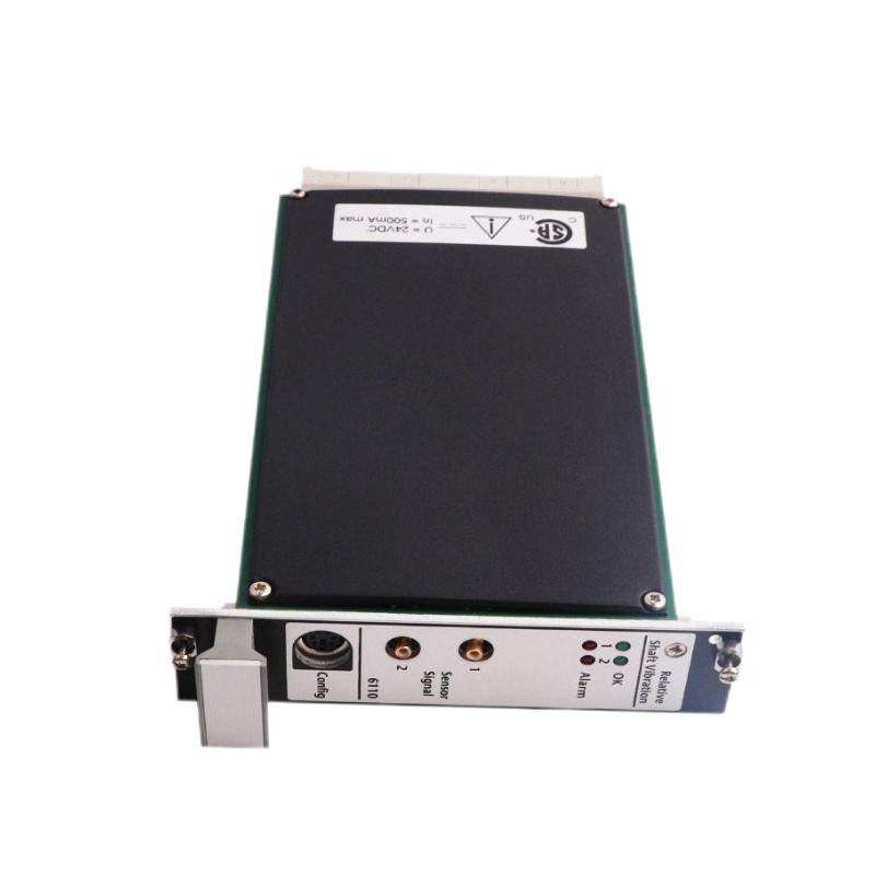
1. Introduction
The Emerson A6110 Shaft Relative Vibration Monitor is a protection and monitoring module designed for use in the AMS 6500 Machinery Health Monitor system. It measures shaft relative vibration through eddy-current displacement sensor systems and provides machinery condition information for monitoring, alarm management, and protection functions. The A6110 is used in applications where reliable shaft vibration measurement is essential, including steam turbines, gas turbines, compressors, pumps, and other rotating machinery. Its measurement performance depends on the complete signal chain: the proximity probe, extension cable, sensor driver, field wiring, monitor input, configuration parameters, and rack power supply. When an abnormal reading or alarm occurs, replacing the monitor immediately is not always the best approach. A systematic inspection can help identify whether the problem originates in the sensor system, wiring, configuration, monitor hardware, or connected protection equipment. This guide explains practical troubleshooting procedures for Emerson A6110 modules. Exact diagnostic behavior and configuration details should always be checked against the installed module revision and the applicable AMS 6500 system documentation.
2. Common A6110 Fault Symptoms
The following symptoms are useful starting points when diagnosing an A6110 installation.
| Observed Symptom | Possible Cause | Recommended Inspection |
|---|---|---|
| No channel measurement | Missing sensor supply, disconnected probe, wiring fault, or channel configuration issue | Check rack power, sensor driver, field cable, and channel status |
| Unstable vibration reading | Loose connections, damaged cable, electrical interference, or mechanical vibration changes | Inspect the complete sensor circuit and compare with independent measurements |
| Incorrect shaft vibration value | Incorrect probe gap, calibration mismatch, measuring range, or sensor configuration | Verify probe installation, driver compatibility, and monitor settings |
| Unexpected Alert or Danger alarm | Actual machine vibration, incorrect setpoints, signal disturbance, or configuration error | Confirm the process condition before changing alarm settings |
| Channel OK indication abnormal | Sensor circuit fault, monitor self-check issue, or channel configuration problem | Review channel diagnostics and inspect the probe, cable, and driver |
| Buffered output unavailable | Output connection problem, incorrect test arrangement, or internal module fault | Check the approved output connection and compare with monitor readings |
| Both channels affected | Shared power, rack, configuration, or common wiring issue | Inspect common system components before replacing individual sensors |
3. Safety Precautions Before Troubleshooting
The A6110 may form part of a machinery protection system. Incorrect intervention can affect alarm availability or protective shutdown functions. Troubleshooting must therefore follow the site’s machinery safety and maintenance procedures.
- Confirm the operating condition of the protected machine before working on the monitoring system.
- Do not disable trips, bypass protection channels, or alter alarm limits without authorization.
- Follow lockout/tagout procedures before disconnecting field wiring or removing equipment where required.
- Verify that the rack and connected circuits are safe to work on before handling connectors.
- Use suitable electrostatic discharge protection when handling the A6110 module.
- Do not assume that a hot-swappable design permits live removal in every installation. Follow the approved site procedure and assess the protection risk first.
- Never connect test equipment to unidentified terminals or pins. Use the correct wiring documentation for the installed revision.
4. Troubleshooting Sensor and Probe Problems
The eddy-current probe system is a critical part of the A6110 measurement chain. A defective probe, incorrect installation gap, incompatible driver, or damaged extension cable can produce incorrect readings or channel fault indications.
4.1 Inspect the Proximity Probe
Check the probe for physical damage, contamination, loose mounting, and signs of overheating. Confirm that the probe is installed securely and that its sensing surface is not damaged. An incorrect probe-to-shaft gap can cause the monitor to report an abnormal displacement value. If the measured gap voltage is outside the expected range, verify the probe installation and calibration using the manufacturer’s specified procedure. Do not adjust the probe gap simply to eliminate an alarm. First establish whether the alarm represents a genuine machine condition or a measurement-system problem.
4.2 Check Probe and Driver Compatibility
The A6110 is intended for use with compatible Emerson eddy-current displacement sensor systems, including applicable PR6422, PR6423, PR6424, and PR6425 probe families and their corresponding driver arrangements. Check the complete probe, extension cable, and driver combination. Similar-looking components are not necessarily interchangeable. Confirm the exact model and calibration characteristics before replacing any part.
4.3 Inspect the Extension Cable
A damaged or incorrectly connected extension cable may cause unstable readings, signal loss, or channel faults.
- Inspect connectors for corrosion, contamination, and mechanical damage.
- Check that cable connections are secure at both ends.
- Look for crushed, sharply bent, or abraded cable sections.
- Verify that the installed cable length and type match the approved sensor arrangement.
- Check cable routing for possible electrical interference from power cables or high-current equipment.
Where permitted by the maintenance procedure, compare the suspect circuit with a known-good compatible sensor circuit. Change only one component at a time so that the source of the fault can be identified.
5. Troubleshooting Signal and Measurement Problems
The A6110 processes the sensor signal to calculate shaft relative vibration. A correct sensor signal can still produce an incorrect measurement if the channel settings do not match the installed sensor system or the required measurement range.
5.1 Verify the Measurement Range
The A6110 supports configurable measuring ranges. If the selected range does not match the intended application, the displayed value may be scaled incorrectly or may reach the measurement limit unexpectedly. Review the configured channel range and compare it with the engineering requirements. Confirm the measurement units, scaling, and sensor calibration before making adjustments.
5.2 Check Frequency Filtering
The monitor provides configurable frequency response settings. Incorrect lower or upper frequency limits may cause relevant vibration components to be excluded or may allow unwanted signal content into the measurement. When vibration readings differ from another instrument, check that both measurement systems use comparable frequency ranges and measurement definitions. Do not change filtering parameters without understanding their effect on the machinery protection strategy.
5.3 Investigate Unstable Readings
If the displayed value fluctuates unexpectedly, inspect the following:
- Probe mounting and mechanical stability.
- Probe gap and shaft surface condition.
- Extension cable and connector integrity.
- Electrical grounding and shielding arrangements.
- Potential interference from nearby drives, contactors, or high-current wiring.
- Changes in actual machine speed, load, bearing condition, or operating state.
Compare the A6110 reading with other available machinery measurements. A vibration change that appears simultaneously in independent monitoring channels may indicate a real machine condition rather than an electronic fault.
6. Alert and Danger Alarm Troubleshooting
The A6110 supports machinery condition alarm functions, including Alert and Danger thresholds. An alarm may indicate genuine vibration exceeding the configured limit, but it can also result from an incorrect setpoint, signal disturbance, or sensor circuit problem.
6.1 Confirm Whether the Alarm Is Genuine
Before changing any alarm setting, check the machine’s operating condition and compare the reading with historical trends and other available measurements. Consider whether the alarm occurred during startup, shutdown, a load change, or another operating transition. Review the vibration trend rather than relying only on a single instantaneous value.
6.2 Review Alarm Configuration
Verify the configured Alert and Danger setpoints, delay, hysteresis, and any applicable channel logic. Compare the configuration with the approved machinery protection documentation. Do not increase an alarm threshold merely to suppress repeated alarms. If the reading is genuine, changing the threshold may reduce the effectiveness of machinery protection.
6.3 Check Remote Functions and Bypass Conditions
Where the installation uses remote limit multiplication or trip-bypass functions, verify the associated control logic and field input status. Confirm that any bypass is authorized, documented, and removed when the maintenance activity is complete.
7. Diagnosing Channel Status and Monitor Self-Checks
The A6110 includes internal monitoring functions intended to detect problems involving the module and its measurement channels. Status LEDs and system diagnostics can help distinguish a channel-level issue from a rack or module-level problem. If a channel OK indication is abnormal, inspect the sensor circuit first. Check the probe, driver, extension cable, wiring, and configured channel parameters. If both measurement channels show abnormal behavior, investigate common causes such as rack power, shared wiring, grounding, or a module-level fault. If the module reports an internal diagnostic problem after external connections and configuration have been verified, record the module identification and diagnostic information. A qualified technician should determine whether the module requires repair, testing, or replacement.
8. Buffered Output and Proportional Output Problems
The A6110 can provide buffered sensor signals and configured proportional outputs for integration with other monitoring or control equipment. A problem at an output does not automatically mean that the primary vibration measurement is faulty.
8.1 Check the Buffered Sensor Output
If the buffered output is missing or appears abnormal, compare it with the channel measurement and check the approved output connection. Confirm that the test instrument is suitable for the signal and that the measurement is performed using the correct procedure.
8.2 Check the Proportional Output
For installations using current or voltage proportional outputs, verify the configured output type and the receiving device’s input requirements. Check field wiring, loop continuity where applicable, and the receiving system’s scaling. Do not assume that every A6110 installation uses the same output configuration. Confirm the actual configuration before testing or replacing connected equipment.
9. Rack Power and Module-Level Troubleshooting
If the A6110 does not start normally or several channels are affected, inspect the rack and power system.
- Confirm that the AMS 6500 rack power supply is operating normally.
- Check for rack-level diagnostic indications or other modules reporting related faults.
- Inspect the A6110 for visible physical damage, contamination, or signs of overheating.
- Confirm that the module is correctly seated in its assigned slot.
- Review whether recent maintenance, wiring changes, or configuration downloads preceded the problem.
The A6110 uses a 24 VDC supply arrangement within its system design. Verify the actual supply condition using the approved rack test procedure rather than probing unidentified module contacts. If the rack has a known power problem, resolve it before condemning the monitor module.
10. A6110 Replacement and Post-Repair Verification
If troubleshooting confirms that the A6110 itself is defective, replacement should be carried out by qualified personnel using an approved maintenance procedure. Before removing the original module, record its identification, slot position, channel configuration, alarm settings, and relevant system status. Confirm that a suitable replacement has the correct hardware revision and system compatibility. After replacement:
- Verify that the module is installed in the correct rack slot.
- Confirm that the rack recognizes the module and that its status indications are normal.
- Check the sensor connections and channel configuration.
- Verify measurement scaling and frequency settings.
- Confirm that Alert and Danger settings match the approved configuration.
- Check buffered and proportional outputs where they are used.
- Verify alarm and relay behavior using the approved commissioning procedure.
- Document the repair and confirm that all temporary bypasses or maintenance overrides have been removed.
Do not return the machinery protection function to normal service until the responsible personnel have confirmed that the required monitoring and protection functions are available.
11. Preventive Maintenance Recommendations
Routine inspection can reduce avoidable A6110 faults and improve the reliability of the complete machinery monitoring system.
- Inspect probe mounting, cable routing, and connector condition during scheduled maintenance.
- Maintain accurate records of probe, extension cable, and driver model numbers.
- Keep a backup of approved channel and alarm configurations.
- Review vibration trends to identify gradual changes before they develop into serious faults.
- Check rack condition and power supply status during planned system inspections.
- Use compatible replacement components and verify calibration after sensor-system changes.
- Record recurring channel faults and investigate common environmental or wiring causes.
12. Frequently Asked Questions
What does the Emerson A6110 monitor?
The A6110 measures shaft relative vibration using compatible eddy-current displacement sensor systems. It is designed for machinery condition monitoring and protection applications within the AMS 6500 platform.
Why does the A6110 show an abnormal vibration value?
Possible causes include a genuine change in machine vibration, incorrect probe gap, sensor or cable damage, incompatible driver components, incorrect channel scaling, or unsuitable frequency settings. The complete measurement chain should be checked before replacing the monitor.
Can a faulty proximity probe cause an A6110 channel alarm?
Yes. A disconnected, damaged, incorrectly installed, or incompatible probe system can affect the channel signal and may cause abnormal status indications or measurements.
Why are the two A6110 channels both showing problems?
When both channels are affected, check common system components such as rack power, shared wiring arrangements, grounding, and module-level diagnostics. Two simultaneous sensor failures are not the only possible explanation.
Should the A6110 be replaced when an alarm occurs?
Not necessarily. First determine whether the alarm represents a real machine condition, a sensor-system fault, a configuration issue, or an internal monitor problem. Replace the module only when the diagnostic evidence supports that decision.
Can the A6110 be removed while the system is powered?
Although the module is designed for an industrial rack environment, live removal must not be assumed to be safe in every installation. Follow the approved AMS 6500 and site-specific maintenance procedure, including protection-system risk controls.
13. Technical Summary
The Emerson A6110 Shaft Relative Vibration Monitor is an important component of the AMS 6500 machinery monitoring and protection system. Reliable operation depends on the correct interaction of the proximity probe, extension cable, driver, field wiring, channel configuration, rack power, and connected output equipment. Effective troubleshooting should begin with the complete sensor signal chain and proceed through measurement settings, alarm configuration, module diagnostics, and rack-level checks. This approach helps maintenance personnel distinguish genuine machinery vibration from instrumentation faults and avoid unnecessary module replacement. For industrial facilities maintaining Emerson AMS 6500 systems, correct diagnosis, compatible replacement components, and documented post-repair verification are essential to maintaining dependable shaft vibration monitoring.