

ProductPRODUCT
Featured products
Contact Us
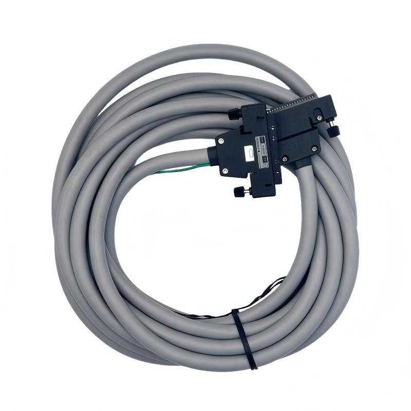
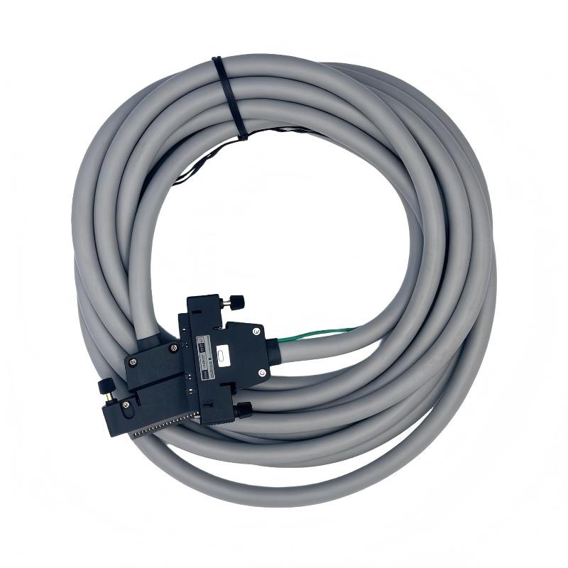
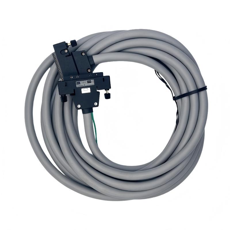
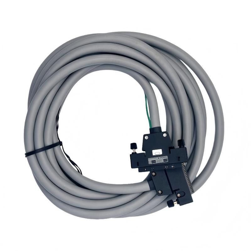
- Yokogawa
- AKB651-M015
- Signal Cable
- Japan
- 15 meters
- 3 kg
- Xiamen, China
- New & In Stock
- T/T, PayPal, Western Union
- 1 Year
- 1-3 Working Days
- DHL, UPS, TNT, FedEx and EMS.
- 24-Hour Service
- COO
- 18
Our advantage

Global Logistics
We have a 10-year logistics and express cooperation agreement, so our products can be shipped to any place in the world.

Brand new and original
Our products are imported in bulk from the place of origin. Because of the cooperative relationship, our products are all original and 100% new.

24-hour service
We provide 7*24 hours service to our customers. We will be there whenever you need us.

Price advantage
All our products are priced very favorably because we have our own warehouse and supply.
| Company Information | |||
| [email protected] | |||
| Mobile | +8615980777398 | ||
| +8615980777398 | |||
| 15980777398 |
Product Overview
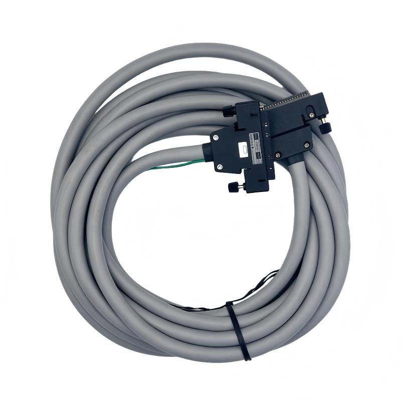
The Yokogawa AKB651-M015 Signal Cable is an industrial connection cable designed for signal transmission between compatible control modules and terminal boards in Yokogawa automation systems. It belongs to the AKB651 cable series and features a 50-pin to 50-pin connector arrangement.
With a specified cable length of 15 meters, the AKB651-M015 supports installations where the connected control equipment and terminal board are positioned at a distance from each other. It helps establish an organized electrical connection between designated system interfaces while supporting the structured wiring requirements of industrial automation installations.
In process automation, signal cables are essential components of the connection infrastructure. They link control-system modules with terminal boards and other designated interfaces, allowing electrical signals to pass between different parts of an automation installation. The correct cable model, connector arrangement, and length are important for maintaining system compatibility.
The AKB651 series is documented for connections between designated Yokogawa digital output modules and terminal boards. The AKB651-M015 is a 15-meter version of this cable family. Depending on the selected equipment configuration, applicable module models include SDV521, SDV531-L, SDV53A, and SDV541.
The cable should not be treated as a universal connection cable for all Yokogawa modules. Before installation or replacement, users should confirm the module model, connector type, pin assignment, and any required special cable option.
Technical Specifications
| Parameter | Specification |
|---|---|
| Brand | Yokogawa |
| Manufacturer | Yokogawa Electric Corporation |
| Model | AKB651-M015 |
| Product Type | Signal Cable |
| Cable Series | AKB651 |
| Connector Configuration | 50-pin to 50-pin |
| Cable Length | 15 meters |
| Shipping Weight | 3 kg |
| Typical Connection | Compatible digital output module to terminal board |
| Applicable Module Families | SDV521, SDV531-L, SDV53A, SDV541, subject to configuration |
| Product Application | Industrial automation signal connection |
Note: The 3 kg figure is the supplied shipping weight, not a confirmed cable net weight. Confirm the actual package weight and dimensions with the supplier before arranging transportation.
Function and Working Principle
The AKB651-M015 provides a physical electrical connection between compatible automation-system interfaces. Its role is to carry designated signals through a multi-pin cable assembly.
1. Signal Transmission
Industrial automation systems rely on electrical signals to exchange information between control modules, terminal boards, and field wiring. The AKB651-M015 provides the cable path for the signals assigned to its connector pins.
The cable’s 50-pin to 50-pin arrangement allows it to connect compatible interfaces without requiring individually wired conductors for each signal.
2. Module-to-Terminal Board Connection
The AKB651 series is designed for specific connections between Yokogawa digital output modules and terminal boards. In a typical arrangement, one end connects to the designated module interface while the other connects to the corresponding terminal-board interface.
The correct connection depends on the module and terminal-board configuration. Users should follow the applicable Yokogawa wiring documentation rather than relying on connector appearance alone.
3. Multi-Channel Signal Interconnection
A multi-pin connector arrangement allows multiple signal paths to be carried within a single cable assembly. This can simplify wiring organization and reduce the need for separate individual connections between compatible equipment.
The actual signals carried by each pin depend on the connected module and its assigned terminal-board wiring.
4. Connection Reliability
A correctly selected and installed cable helps maintain a stable electrical connection between system components. Proper connector engagement, cable routing, strain relief, and protection from mechanical damage are important for long-term operation.
Cable condition should be inspected during maintenance, especially in installations subject to vibration, repeated movement, or frequent equipment access.
Role in Yokogawa Industrial Control Systems
The AKB651-M015 can form part of the connection infrastructure in a Yokogawa industrial control system. It supports the physical signal path between designated control modules and terminal boards.
Digital Output Module Integration
Digital output modules provide switching signals to external devices such as relays, solenoid valves, and other control equipment. The AKB651 series is documented for use with selected Yokogawa digital output modules.
When installed in the specified configuration, the cable connects the module interface to the terminal board, supporting the transfer of the module’s assigned output signals.
Terminal Board Integration
Terminal boards provide an organized interface between control-system modules and external field wiring. They help arrange signal connections and simplify the wiring structure of industrial control cabinets.
The AKB651-M015 provides the cable connection required for compatible module-to-terminal-board arrangements.
Distributed Control System Wiring
In a distributed control system, equipment is often installed across different sections of a control cabinet or system enclosure. Suitable cable lengths help accommodate the physical arrangement of the components.
The 15-meter length of the AKB651-M015 can be considered where the installation requires a longer cable route than shorter AKB651 versions. The cable length must still comply with the system’s electrical and application-specific limitations.
Process Automation Maintenance
During maintenance or equipment replacement, identifying the correct signal cable is important. A cable with the same number of pins may still have a different pin assignment or intended application.
Using the exact model number helps maintenance teams reduce the risk of incorrect connections and unnecessary wiring modifications.
Industrial Applications
1. Process Automation Systems
Process plants use control modules and terminal boards to manage signals associated with production equipment. The AKB651-M015 can be used in compatible Yokogawa system configurations where the specified cable connection is required.
Typical environments include chemical processing, manufacturing, energy production, and other process-control installations.
2. Digital Output Signal Connections
Digital output modules control external devices through discrete electrical signals. The AKB651 series supports designated connections between compatible output modules and terminal boards.
The exact module and terminal-board combination must be confirmed before selecting the cable.
3. Industrial Control Cabinets
Control cabinets contain PLCs, DCS components, terminal boards, power supplies, and other automation equipment. The 15-meter cable length can accommodate suitable layouts where the connected interfaces are separated by a longer routing distance.
Proper routing and cable management help maintain cabinet organization and simplify future maintenance.
4. Yokogawa ProSafe-RS Installations
The AKB651 series has documented applications involving selected Yokogawa modules used in ProSafe-RS configurations. Special cable options are available for certain module types.
When the cable is used with SDV521, SDV531-L, SDV53A, or SDV541, the applicable model and option code must be checked. The cable length must also meet the system’s connection limitations.
5. Equipment Replacement and System Maintenance
The AKB651-M015 may be used in maintenance projects where an existing 15-meter AKB651 cable needs replacement. It is important to verify the original part number and system configuration before ordering.
A replacement should match the connector arrangement, cable type, pin assignment, and required length.
Installation and System Integration
Correct installation is important for maintaining signal integrity and preventing connection problems.
1. Verify the Equipment Model
Before installation, identify the exact Yokogawa module and terminal board. The AKB651 series is intended for designated connections, not unrestricted use with every 50-pin interface.
Check the relevant system documentation to confirm that the cable is approved for the intended module combination.
2. Confirm Connector Compatibility
Inspect both cable connectors and compare them with the equipment interfaces. Check connector type, pin arrangement, keying, and mechanical condition.
Never force a connector into an interface. Incorrect alignment or excessive insertion force can damage connector contacts.
3. Check the Cable Route
The AKB651-M015 has a nominal length of 15 meters. Plan the cable route before installation and avoid unnecessary tension, sharp bends, and excessive mechanical stress.
The cable should be routed so that it does not interfere with cabinet doors, moving equipment, maintenance access, or other wiring.
4. Separate Signal and Power Wiring
Where required by the system design, keep signal cables separated from high-power conductors and sources of electrical interference.
Follow the applicable wiring instructions for cable routing, grounding, shielding, and separation distances. Do not assume that every installation uses the same grounding arrangement.
5. Inspect and Secure the Cable
Check the cable jacket, connector housing, and contact area for visible damage. Ensure the connectors are fully engaged and that the cable is supported to prevent strain on the connection points.
Avoid tight cable ties that may deform or damage the cable assembly.
6. Perform Connection Verification
After installation, verify that the connected equipment recognizes the intended signals and that the system operates correctly.
For digital output applications, perform appropriate functional checks of the relevant output channels and connected field devices. Any testing should follow the plant’s approved maintenance and safety procedures.
Compatible System Components
The AKB651-M015 is used as part of a specific Yokogawa connection arrangement. The following components describe its typical system context.
| Component | Function | Compatibility Considerations |
|---|---|---|
| Yokogawa SDV521 | Digital output module | Confirm the applicable AKB651 special cable option and system requirements |
| Yokogawa SDV531-L | Digital output module | Verify the specified cable option and module configuration |
| Yokogawa SDV53A | Digital output module | Check the module and terminal-board connection documentation |
| Yokogawa SDV541 | Digital output module | Confirm the applicable cable option and connection limitations |
| Terminal Board | Provides an interface for field wiring | Verify the exact terminal-board model and connector assignment |
| Yokogawa Control System | Coordinates industrial process signals | Confirm the cable’s role in the installed system architecture |
| Field Wiring | Connects terminal-board channels to external devices | Follow the assigned terminal and signal specifications |
Compatibility depends on the complete hardware configuration. A 50-pin connector alone does not establish that two devices can be connected safely.
Alternative Models and Replacement Considerations
The AKB651 cable series offers multiple length options. These models share the same general cable family but differ in length and may require different special options depending on the connected equipment.
| Model | Cable Length | Application Consideration |
|---|---|---|
| AKB651-M001 | 1 m | Short-distance connection |
| AKB651-M002 | 2 m | Compact cabinet connection |
| AKB651-M003 | 3 m | Short equipment interconnection |
| AKB651-M005 | 5 m | Medium-distance connection |
| AKB651-M007 | 7 m | Medium-distance system wiring |
| AKB651-M010 | 10 m | Longer control-cabinet routing |
| AKB651-M015 | 15 m | Extended connection distance |
| AKB651-M020 | 20 m | Longer equipment separation |
| AKB651-M025 | 25 m | Extended system installation |
| AKB651-M030 | 30 m | Maximum listed AKB651 length |
The suffix identifies the nominal cable length. It does not independently confirm compatibility with every module.
Before choosing an alternative, compare:
- Cable series and model number.
- Connector arrangement and pin configuration.
- Connected module and terminal-board models.
- Required cable length.
- Any special module-specific cable option.
- System connection limitations.
- Cable routing and environmental conditions.
Do not replace the AKB651-M015 with another Yokogawa signal cable simply because the connector appears similar. Other cable families may have different pin arrangements and intended applications.
Key Advantages
15-Meter Cable Length
The AKB651-M015 provides a nominal 15-meter connection length for installations where a longer cable route is required.
50-Pin to 50-Pin Connection
Its connector arrangement is designed for compatible 50-pin interfaces, supporting organized interconnection between designated Yokogawa components.
Dedicated AKB651 Series Identification
The model number identifies the cable family and length, helping maintenance personnel select the correct spare part.
Support for Yokogawa System Wiring
The AKB651 series is documented for specific digital output module and terminal-board connections.
Simplified Cable Management
A multi-pin cable assembly can reduce the need for separate individual connections between compatible interfaces and help maintain an organized wiring layout.
Maintenance and Replacement Use
The exact model number supports equipment identification and replacement planning in existing Yokogawa installations.
Technical FAQs
1. What is the Yokogawa AKB651-M015?
The AKB651-M015 is a Yokogawa 50-pin to 50-pin signal cable with a nominal length of 15 meters. It is designed for designated connections between compatible control modules and terminal boards.
2. What does M015 mean in the model number?
The suffix M015 identifies the cable length as 15 meters.
3. What type of connectors does the cable use?
The AKB651 series is specified as a 50-pin to 50-pin signal cable. Confirm the physical connector details and pin assignment against the connected equipment documentation.
4. Which Yokogawa modules can use the AKB651 series?
The documented applications include connections involving SDV521, SDV531-L, SDV53A, and SDV541 digital output modules and their designated terminal boards. The correct special cable option and configuration must be verified.
5. Can the AKB651-M015 be used with any Yokogawa 50-pin interface?
No. Connector pin count alone does not establish compatibility. The module model, pin assignment, electrical characteristics, and intended application must match.
6. Is the AKB651-M015 suitable for ProSafe-RS systems?
The AKB651 series has documented applications in selected ProSafe-RS configurations. Confirm the exact module and required special cable option before installation.
7. What is the shipping weight?
The supplied shipping weight is 3 kg. This should be treated as the package weight rather than a confirmed cable net weight.
8. Can a shorter AKB651 cable replace the M015 version?
A shorter version may be suitable only if it reaches the connected interfaces and meets the system’s cable-length limitations. The correct length should be selected according to the installation and applicable Yokogawa documentation.
9. What should be checked before replacing the cable?
Confirm the original model number, connector arrangement, pin assignment, cable length, connected module, terminal board, and any special option code.
10. How should the cable be maintained?
Inspect the cable jacket, connectors, and routing condition periodically. Avoid sharp bends, excessive pulling force, and exposure to conditions outside the cable’s specified operating environment.
Procurement and Maintenance Recommendations
When purchasing the Yokogawa AKB651-M015, verify the complete model number and ensure that the cable is the 15-meter version of the AKB651 50-pin to 50-pin series.
For replacement projects, obtain the original cable identification and confirm the connected module and terminal-board models. If the cable is used with SDV521, SDV531-L, SDV53A, or SDV541, check the required special cable option and any applicable connection limitations.
For warehouse management, distinguish the cable’s nominal length from its shipping weight. The supplied 3 kg value should be used as a shipping reference only after confirming the actual package information.
During maintenance, inspect connectors for bent contacts, contamination, or physical damage. Check the cable jacket for cuts, crushing, and abrasion. Keep the cable properly supported and routed away from sources of mechanical damage and electrical interference.
For critical control-system connections, use the specified cable model and follow the manufacturer’s installation documentation. Accurate part-number verification helps reduce wiring errors and supports reliable maintenance of Yokogawa automation equipment.
Conclusion
The Yokogawa AKB651-M015 Signal Cable is a 15-meter, 50-pin to 50-pin connection cable designed for specific industrial automation applications. The AKB651 series supports designated connections between compatible Yokogawa digital output modules and terminal boards, including selected ProSafe-RS configurations.
Its correct use depends on the connected module, terminal-board model, pin assignment, and any required special cable option. For maintenance and procurement projects, verifying these details is essential to selecting a suitable replacement and maintaining reliable signal connections in industrial control systems.