
NewsNEWCENTER
Featured products
Contact Us
GE DS215TCQBG1BZZ01A (DS200TCQBG1BBA) Extended Analog I/O Board Troubleshooting and Fault Diagnosis Guide
2026-11-02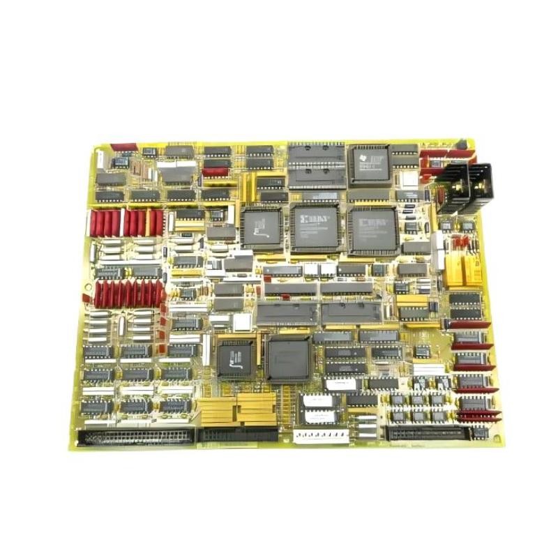
1. Introduction
The **GE DS215TCQBG1BZZ01A (DS200TCQBG1BBA) Extended Analog I/O Board** is associated with the GE Mark V Speedtronic turbine control system. It provides extended analog I/O capability in applicable turbine control configurations and supports the acquisition and handling of analog signals required for equipment monitoring and control. Faults involving this board may appear as abnormal analog readings, board diagnostic alarms, missing input signals, or inconsistencies between redundant control cores. However, these symptoms do not automatically indicate that the TCQB board itself has failed. Field wiring, connected instruments, configuration settings, memory devices, connectors, and other Mark V components can also contribute to similar problems. This guide explains a practical troubleshooting process, common symptoms, inspection methods, and replacement considerations for maintenance engineers and industrial control technicians.
2. Understanding the Board Before Troubleshooting
The TCQB is an RST Extended Analog I/O Board used in compatible GE Mark V installations. Depending on the system architecture, the board may be installed in the R, S, and T control cores. Simplex and redundant configurations do not necessarily use the same hardware arrangement. Before diagnosing a fault, confirm the complete assembly identification:
| Item | Identification |
|---|---|
| Manufacturer | General Electric (GE) |
| Assembly Number | DS215TCQBG1BZZ01A |
| Functional Board Number | DS200TCQBG1BBA |
| Functional Acronym | TCQB |
| Product Type | RST Extended Analog I/O Board |
| Control Platform | Mark V Speedtronic |
| Primary Role | Extended analog I/O functionality |
Always check the complete part number and revision. Other TCQB assemblies may look similar but should not be assumed to have identical hardware or configuration.
3. Common Symptoms and Possible Causes
3.1 Analog Input Values Are Missing
One or more configured analog values may appear unavailable, invalid, or frozen in the control system. Possible causes include:
- Loose or damaged field wiring.
- Incorrect connector seating.
- Faults in the connected field instrument.
- Incorrect channel assignment or system configuration.
- Board hardware failure.
- A problem elsewhere in the signal path.
Recommended checks: 1. Identify the affected channel and compare its current value with the expected field condition. 2. Review Mark V diagnostic information for related channel or board alarms. 3. Inspect the field instrument and wiring using approved procedures. 4. Check the corresponding board connections and termination path. 5. Compare related readings in other control cores where the architecture supports this comparison. Do not replace the TCQB board before checking the complete signal path.
3.2 Analog Readings Are Unstable
Unstable readings may appear as continuous fluctuations, intermittent spikes, or values that change unexpectedly. Potential causes include electrical interference, poor shielding, grounding problems, damaged cables, unstable field instruments, or incorrect hardware configuration. Recommended checks: – Inspect cable routing and separation from high-power conductors. – Check shielding and grounding against the plant wiring design. – Examine terminals and connectors for corrosion or looseness. – Compare the signal with an independent measurement where practical. – Review whether the problem affects one channel or several channels. If several channels show similar behavior, investigate common wiring, grounding, power, or hardware-interface conditions before concluding that multiple input channels have failed.
3.3 Board Diagnostic Alarm
A board-related alarm may indicate a hardware problem, configuration mismatch, connection issue, or another abnormal condition detected by the Mark V system. Recommended troubleshooting: 1. Record the exact alarm text and occurrence time. 2. Determine whether the alarm is continuous or intermittent. 3. Check whether other boards in the same control core report related faults. 4. Review the board’s installation position and connector engagement. 5. Verify the installed board identity and revision. 6. Consult the applicable Mark V diagnostic documentation before taking corrective action. Avoid clearing alarms without recording their original status. Repeatedly resetting the system without identifying the cause can make fault diagnosis more difficult.
3.4 R, S, and T Core Readings Do Not Match
In applicable redundant Mark V configurations, inconsistent readings between control cores may indicate a difference in signal acquisition, configuration, wiring, or board condition. Possible causes include: – Different hardware revisions or configurations. – A connector or cable problem affecting one core. – Incorrect channel mapping. – A field signal problem. – A fault in one of the associated boards. – A difference in the signal path between cores. Recommended checks: Compare corresponding signal values and diagnostic records across the configured cores. Identify whether the discrepancy is limited to one core, one channel, or a group of related signals. Do not assume that every difference represents a TCQB hardware failure. The complete signal path and system configuration must be evaluated.
3.5 Fault Appears After Board Replacement
If a fault begins immediately after replacing the board, review the replacement process carefully. Common possibilities include: – Incorrect replacement assembly or revision. – Incorrect board position. – Poorly seated connectors. – Incorrectly transferred EPROM devices, where applicable. – Different hardware configuration or jumper settings. – Wiring returned to the wrong connector. – Incompatible application configuration. Compare the installed replacement with the original board and the approved turbine-specific documentation. Check every connection and configuration element before considering further hardware changes.
4. Step-by-Step Troubleshooting Procedure
Step 1: Collect Diagnostic Information
Before touching the hardware, collect the available control-system information. Record:
- Exact board and assembly identification.
- Control-core location and installation position.
- Alarm messages and diagnostic codes.
- Affected analog channels.
- Whether the problem is continuous or intermittent.
- Whether the fault appeared after maintenance or a hardware change.
- Differences between the R, S, and T cores, where applicable.
This information helps distinguish a board-level fault from a field-device or configuration problem.
Step 2: Check the Field Signal Path
Trace the affected signal through the approved wiring drawings. Inspect the field instrument, cable, termination points, and associated connections. Use suitable calibrated instruments only under approved plant procedures. Do not disconnect live signal wiring or perform measurements on energized circuits unless the procedure specifically authorizes the work.
Step 3: Inspect Board Connections
If the signal-path inspection does not identify the problem, arrange an approved shutdown and electrical isolation before inspecting the board. Check: – Connector seating and locking features. – Cable condition and visible insulation damage. – Signs of corrosion or contamination. – Discolored components or evidence of overheating. – Cracked solder joints or damaged PCB areas. – Loose mounting hardware or mechanical damage. The TCQB board is commonly identified by its OK LED, 50-pin connector, and hardware jumpers. Use the correct board revision documentation to interpret any status indication or configuration feature.
Step 4: Verify Hardware Configuration
Check all applicable jumper settings against the original installation records and approved configuration documentation. Certain TCQB applications involving proximity transducers or accelerometers may require specific hardware settings. Incorrect settings can affect signal interpretation and lead to abnormal readings. Do not move jumpers experimentally. Record the original positions before making any approved adjustment.
Step 5: Check EPROM and Firmware Configuration
Some replacement board arrangements may require EPROM devices to be transferred from the original board. If this applies to the installed assembly, verify device identification, compatibility, orientation, and installation position. Incorrect or incomplete memory-device installation can prevent the replacement from operating as intended. Handle EPROM devices using ESD precautions and the approved replacement procedure. Never assume that memory devices from a different TCQB revision are interchangeable.
Step 6: Evaluate the Board
If field wiring, connectors, and configuration have been checked but the fault remains, the board may require specialist testing. Possible evaluation areas include: – PCB inspection for damaged components. – Connector and solder-joint condition. – Power and interface circuit condition. – Hardware configuration verification. – Memory-device condition, where applicable. – Comparison with a verified compatible assembly. Board-level testing should be carried out by qualified personnel using appropriate equipment and revision-specific procedures.
5. Troubleshooting Reference Table
| Symptom | Possible Cause | Recommended Action |
|---|---|---|
| Analog signal missing | Field wiring, instrument, connector, or board fault | Trace the complete signal path and inspect connections. |
| Unstable analog value | Electrical noise, grounding, shielding, or instrument problem | Inspect wiring, grounding, and field signal quality. |
| Board alarm | Hardware, configuration, or interface issue | Record diagnostics and inspect the board installation. |
| RST core disagreement | Different signal paths or configuration conditions | Compare corresponding core diagnostics and channel settings. |
| Fault after replacement | Wrong revision, connection error, or configuration mismatch | Verify the complete assembly identity and installation records. |
| Intermittent fault | Loose connector, damaged cable, or temperature-related component issue | Review event history and inspect hardware during an approved shutdown. |
| Board not operating normally | Board damage, memory-device issue, or incompatible assembly | Arrange qualified board-level inspection and compatibility verification. |
6. When Should the TCQB Board Be Replaced?
Replacement should be considered when diagnostic evidence indicates a persistent board-level problem and the field wiring, connected instruments, configuration, and external interfaces have been checked. Typical reasons for replacement include:
- Visible PCB damage or component overheating.
- Persistent board-related diagnostics after external causes have been eliminated.
- Confirmed internal circuit failure during specialist testing.
- Physical damage to connectors or the PCB.
- Unrecoverable hardware malfunction confirmed by qualified technicians.
Before ordering a replacement, confirm the complete DS215TCQBG1BZZ01A and DS200TCQBG1BBA identification, revision markings, system architecture, and required configuration. A similar-looking TCQB board is not necessarily an approved substitute.
7. Replacement and Post-Repair Verification
After replacing or repairing the board, follow the approved Mark V maintenance and commissioning procedures.
Hardware Verification
Confirm that the replacement is installed in the correct position, connectors are properly seated, and all wiring matches the original drawings.
Configuration Verification
Check the applicable jumper positions, memory-device arrangement, and system configuration records. Confirm that any required configuration restoration has been completed by authorized personnel.
Diagnostic Verification
Review the Mark V diagnostic interface for board-related alarms. Confirm that no new abnormal conditions have appeared following installation.
Analog Signal Verification
Check the affected analog channels against expected operating conditions and approved test values. Confirm that readings are stable and plausible.
Redundant-Core Verification
For RST installations, verify the relevant signal and diagnostic consistency across the configured cores. Complete the required functional checks before returning the affected equipment to normal operation.
8. Preventive Maintenance Recommendations
A structured maintenance program can reduce unexpected failures and improve the reliability of the Mark V analog I/O system. Recommended practices include: 1. Inspect the PCB and connectors during scheduled maintenance. 2. Keep the control cabinet clean and free from conductive dust or contamination. 3. Check for corrosion, overheating, and mechanical damage. 4. Review recurring analog signal alarms and intermittent faults. 5. Maintain accurate records of board revisions and configuration changes. 6. Keep photographs and wiring records before removing installed hardware. 7. Store spare TCQB boards in suitable antistatic packaging. 8. Verify replacement assemblies before installation rather than relying on partial model numbers. Avoid unnecessary board removal, repeated connector handling, and unapproved jumper changes.
9. Frequently Asked Questions
What is the GE DS215TCQBG1BZZ01A used for?
It is an assembly associated with the DS200TCQBG1BBA TCQB RST Extended Analog I/O Board used in compatible GE Mark V Speedtronic turbine control systems.
What are the common symptoms of a faulty TCQB board?
Possible symptoms include missing or abnormal analog readings, board-related diagnostic alarms, intermittent signal problems, and inconsistencies between redundant control cores. These symptoms can also originate from field wiring, instruments, or configuration issues.
Does an analog signal fault always mean the TCQB board needs replacement?
No. Field instruments, termination connections, cables, shielding, grounding, and system configuration should be checked before replacing the board.
What should be checked when installing a replacement?
Verify the complete assembly number, revision, board position, connectors, applicable jumper settings, and EPROM configuration where required.
Can I use another DS200TCQB board as a direct replacement?
Not without verification. The complete part number, revision, hardware configuration, and turbine-specific compatibility must be checked before substitution.
Does the TCQB board require routine calibration?
Do not assume that a generic calibration procedure applies to this board. Signal verification and any adjustment requirements should follow the installed Mark V configuration and the relevant field-device procedures.
Can the board be removed while the turbine control system is energized?
Do not remove or insert the board under power unless an approved site-specific procedure explicitly authorizes it. Follow the plant’s isolation, lockout/tagout, and stored-energy safety requirements.
10. Technical Summary
The GE DS215TCQBG1BZZ01A (DS200TCQBG1BBA) Extended Analog I/O Board is an important component in compatible GE Mark V turbine control configurations. Troubleshooting should begin with diagnostic records and the complete analog signal path, followed by connector inspection, hardware configuration verification, and qualified board-level testing where necessary. The most effective maintenance approach is to identify the actual source of the fault before replacing hardware. Accurate revision matching, correct configuration, careful handling of connectors and memory devices, and thorough post-repair signal verification help maintain reliable operation of the Mark V control system.