

ProductPRODUCT
Featured products
Contact Us
- Ingersoll Rand
- 47553887001 24266025
- Hydraulic Hose Assembly
- USA
- 56 in
- 3 kg
- Xiamen, China
- New & In Stock
- T/T, PayPal, Western Union
- 1 Year
- 1-3 Working Days
- DHL, UPS, TNT, FedEx and EMS.
- 24-Hour Service
- COO
- 6
Our advantage

Global Logistics
We have a 10-year logistics and express cooperation agreement, so our products can be shipped to any place in the world.

Brand new and original
Our products are imported in bulk from the place of origin. Because of the cooperative relationship, our products are all original and 100% new.

24-hour service
We provide 7*24 hours service to our customers. We will be there whenever you need us.

Price advantage
All our products are priced very favorably because we have our own warehouse and supply.
| Company Information | |||
| [email protected] | |||
| Mobile | +8615980777398 | ||
| +8615980777398 | |||
| 15980777398 |
Product Overview
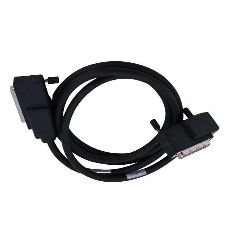
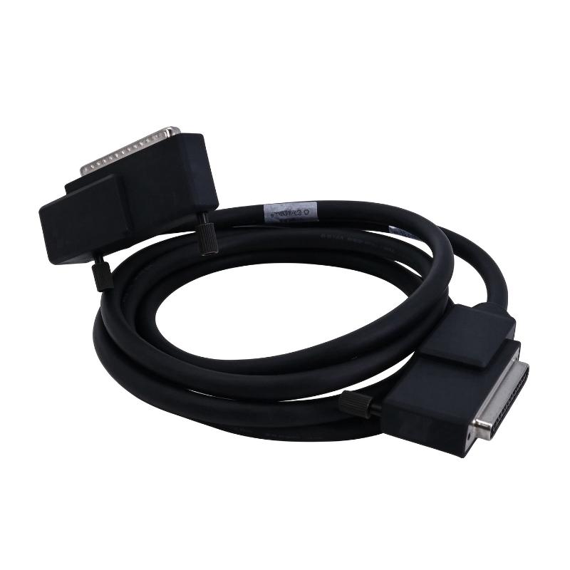
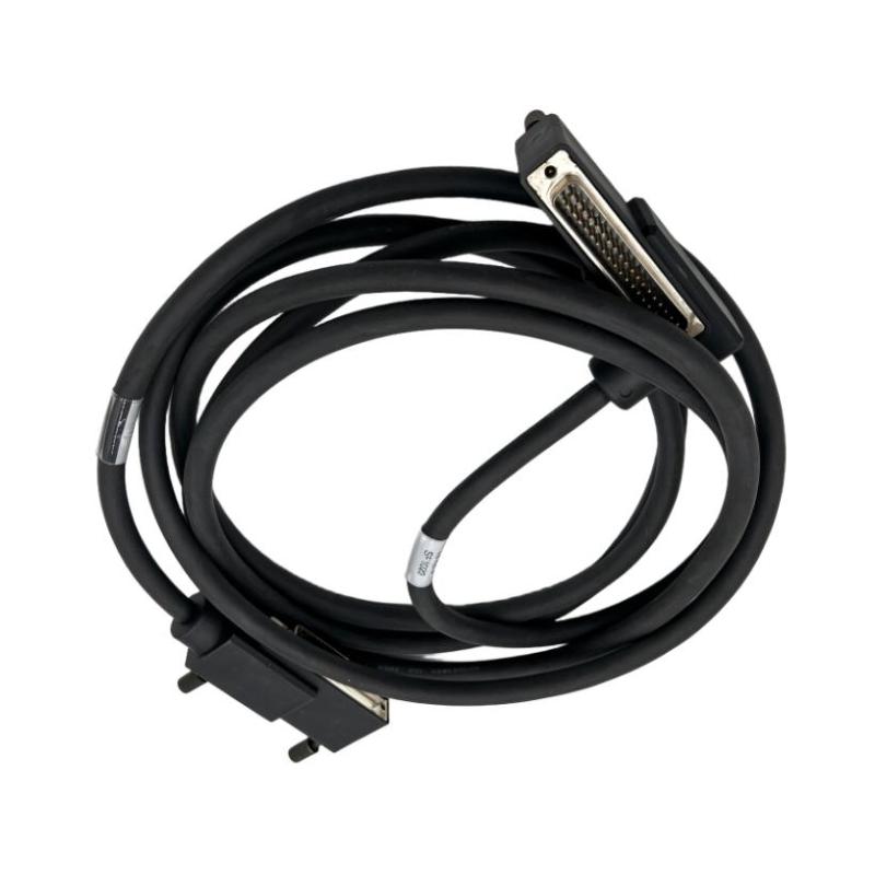
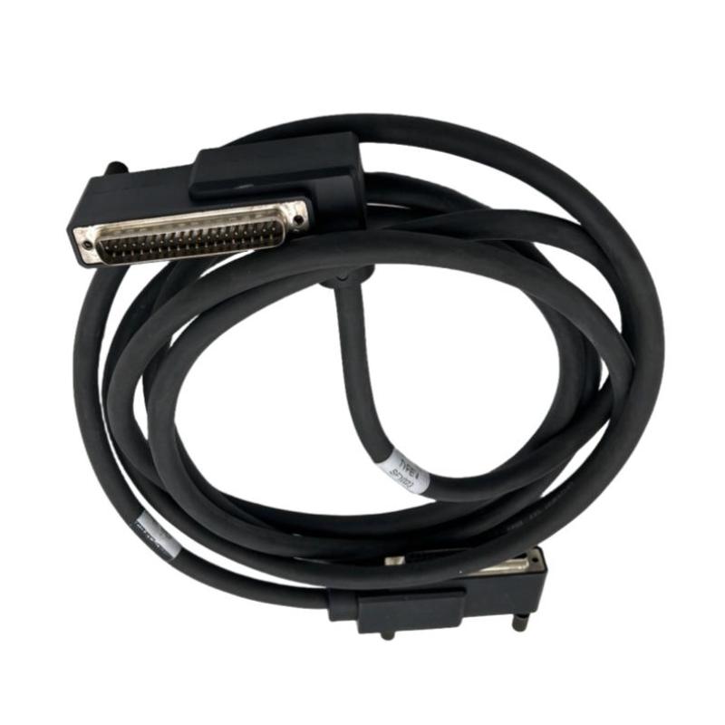
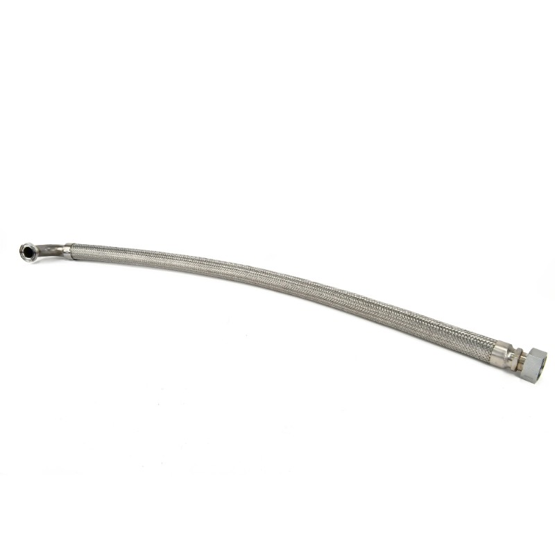
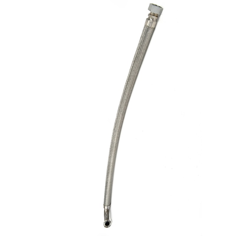
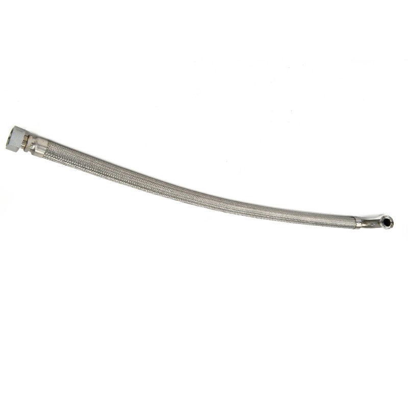
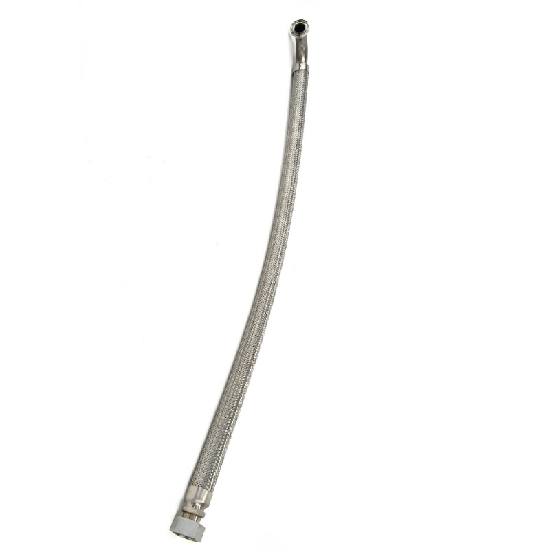
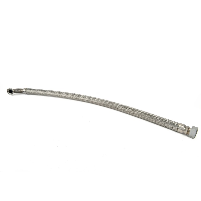
The Ingersoll Rand 47553887001 24266025 Hose is a hydraulic hose assembly used in compatible Ingersoll Rand industrial compressor systems. Identified as a 1.5-inch hydraulic hose with a 56-inch length, part number 24266025 features a 90-degree elbow connection at one end and a straight ORFS connection at the other. This configuration is relevant when routing a large-bore hose through a confined machinery installation.
In a rotary screw compressor, hydraulic hoses can form part of the oil circulation, cooling, or other fluid-handling arrangements, depending on the machine configuration. These connections must accommodate operating pressure, temperature changes, and vibration without developing leaks or restricting flow. A hose with an incorrectly oriented fitting can also create installation problems, even when its nominal length and diameter appear suitable.
The 24266025 configuration is identified as a 1.50-inch hose with an SF 90-degree elbow using an ISO 6162 connection at one end and an ORFS straight connection at the other. This combination distinguishes it from hoses that use straight fittings at both ends or different flange and thread arrangements.
When replacing this component, technicians should verify the full part number, fitting orientation, connection standards, and hose routing against the original assembly. The stated 56-inch length is useful for identification, but matching the connection geometry and pressure requirements is equally important. A hose that fits physically but does not match the original hydraulic specification may compromise the installation.
Technical Specifications
| Parameter | Specification |
|---|---|
| Manufacturer | Ingersoll Rand |
| Product Type | Hydraulic Hose Assembly |
| Part Number | 47553887001 |
| Component Number | 24266025 |
| Hose Type | Hydraulic Hose |
| Nominal Hose Size | 1.50 in |
| Hose Length | 56 in |
| End Connection 1 | 90° Elbow, ISO 6162 |
| End Connection 2 | Straight ORFS |
| Shipping Weight | 3 kg |
Product Features
- Large-bore hydraulic passage: The 1.50-inch nominal hose size identifies the intended connection class for the specified assembly.
- Mixed-end configuration: Combines a 90-degree ISO 6162 elbow connection with a straight ORFS connection.
- Defined routing length: The 56-inch hose length helps technicians compare the replacement against the original installation.
- Angled connection at one end: The elbow fitting can accommodate routing arrangements where a straight flange connection would create clearance problems.
- Assembly-specific identification: The 24266025 component number distinguishes this hose from other hydraulic hose variants.
- Replacement suitability checks: Matching the end connections and routing geometry helps avoid unnecessary strain during installation.
- Hydraulic circuit application: Suitable for the intended compressor circuit when the pressure, temperature, and fluid requirements are met.
Working Principle
The 24266025 hose carries fluid between two connected points in the hydraulic circuit for which it is specified. Its flexible body accommodates the required routing, while the end fittings create the mechanical connections to the associated equipment.
The 90-degree ISO 6162 elbow and straight ORFS end serve different installation geometries. The elbow allows the hose to change direction at the flange connection, while the straight ORFS fitting connects to a compatible port or mating assembly. This arrangement can be useful when the hose must pass around structural members or other compressor components.
A typical hydraulic connection follows this path:
Hydraulic Source → ISO 6162 90° Elbow → Hose 24266025 → Straight ORFS Connection → Receiving Component
When the compressor is operating, the associated circuit moves fluid through the hose under its specified conditions. The hose must maintain the required flow path without excessive bending, twisting, or contact with nearby components. Properly seated fittings and undamaged sealing surfaces help prevent leakage at the connections.
During replacement, the technician should inspect both mating ports and confirm the orientation of the original hose before tightening the new assembly. Incorrect fitting alignment can place torsional stress on the hose body or make it difficult to achieve proper sealing.
The hose itself does not regulate system pressure or control fluid flow. Its performance depends on the complete assembly, including the hose construction, end fittings, sealing interfaces, and compatibility with the operating fluid.
Role in a Compressor Hydraulic System
The 24266025 hose provides a flexible connection between two components in the applicable hydraulic circuit. Its precise position depends on the compressor model and the circuit layout, so the original assembly documentation should be used to identify the connected components.
Hydraulic Circuit Component → ISO 6162 Elbow Connection → 24266025 Hose → ORFS Straight Connection → Connected Equipment
| System Element | Function |
|---|---|
| Hydraulic Source | Supplies fluid to the designated circuit |
| ISO 6162 Flange Connection | Provides the specified connection at the elbow end |
| 24266025 Hose | Carries fluid between the two connection points |
| ORFS Connection | Provides the straight-end connection and sealing interface |
| Receiving Component | Accepts fluid delivered through the hose |
| Hydraulic Circuit | Supports the fluid-handling function assigned to the assembly |
| Maintenance Inspection | Checks fitting integrity, hose condition, and leakage |
Correct hose selection helps preserve the original connection geometry and reduces the risk of installation stress. The precise circuit function must be confirmed for the compressor being serviced.
Industrial Applications
| Application | Typical Use |
|---|---|
| Rotary Screw Compressors | Connecting components within the specified hydraulic or fluid-handling circuit |
| Industrial Compressor Maintenance | Replacing a damaged hose assembly during scheduled service |
| Compressor Overhauls | Renewing hydraulic connections after component removal |
| Large Industrial Machinery | Routing fluid between components with different connection orientations |
| Manufacturing Facilities | Maintaining compressor fluid circuits used in production support |
| Process Industry Equipment | Replacing hoses subject to operating pressure, temperature, and vibration |
| Hydraulic Connection Maintenance | Restoring a specified ISO 6162-to-ORFS hose arrangement |
| Spare Parts Management | Identifying the correct hose through its part number and connection details |
The 24266025 hose should be used only where its connection configuration and operating specifications match the installation. The intended circuit and fluid compatibility should be verified before fitting the replacement.
Installation and Maintenance
- Verify the part number: Confirm that 47553887001 and 24266025 match the hose specified for the compressor assembly.
- Identify the hydraulic circuit: Establish the hose’s original function and connected components before removing it.
- Isolate the equipment: Shut down the compressor, isolate the relevant energy sources, and release stored hydraulic pressure according to the service procedure.
- Record the hose orientation: Note the position of the 90-degree elbow and the direction of the straight ORFS fitting.
- Inspect the replacement hose: Check for cuts, crushing, abrasion, or other damage sustained during storage or handling.
- Check the end fittings: Inspect the ISO 6162 flange interface and ORFS connection for damaged sealing surfaces, contamination, or deformation.
- Clean the mating ports: Remove dirt and residual fluid using an approved method to prevent contamination of the hydraulic circuit.
- Confirm connection compatibility: Verify the fitting standards and dimensions against the original installation before assembly.
- Route the hose correctly: Maintain the intended path and avoid sharp bends, twisting, or contact with hot or moving components.
- Tighten the connections properly: Follow the specified assembly procedure for the flange and ORFS connections rather than relying on an assumed torque value.
- Check for leakage: After assembly, perform the approved inspection or pressure test and check the hose for interference throughout the operating range.
- Document the replacement: Record the installed part number, connection orientation, inspection results, and any defects found during removal.
Never check for hydraulic leaks with bare hands while the system is pressurized. High-pressure fluid can penetrate the skin. Depressurize the circuit before adjusting or removing connections, and follow the site’s hydraulic safety procedures.
Compatible System Components
The 24266025 hose must match the fittings and fluid circuit of the compressor assembly. The following component categories may form part of the surrounding installation, depending on the equipment configuration.
| Component | Function |
|---|---|
| Hydraulic Manifold | Distributes fluid through the designated circuit |
| ISO 6162 Flange Port | Provides the mating connection for the 90-degree elbow end |
| ORFS Port or Fitting | Connects to the straight hose end through the specified sealing interface |
| Hydraulic Pump or Fluid Supply Component | Supplies fluid where the circuit uses a powered fluid source |
| Hydraulic Filter | Removes contaminants from fluid in systems equipped with filtration |
| Fluid Cooler | Controls fluid temperature where incorporated into the circuit |
| Hose Clamps or Supports | Maintain the required routing where specified by the assembly |
Recommended Related Models
| Model | Product Type | Relevance |
|---|---|---|
| Ingersoll Rand 24266017 | Hydraulic Hose | 1.50-inch hose with a 52-inch length and a similar 90-degree ISO 6162-to-ORFS connection arrangement |
| Ingersoll Rand 24266033 | Hydraulic Hose | 1.50-inch hose with a 26-inch length and a 90-degree ISO 6162-to-ORFS configuration |
| Ingersoll Rand 24266041 | Hydraulic Hose | 1.50-inch hose with straight ORFS connections at both ends |
| Ingersoll Rand 24265902 | Hydraulic Hose | 1.25-inch hydraulic hose with a 46-inch length |
| Ingersoll Rand 24265936 | Hydraulic Hose | 1.25-inch hose with a straight ORFS end and a 45-degree ORFS elbow |
| Ingersoll Rand 24265944 | Hydraulic Hose | 1.50-inch hose with a 46-inch length and ORFS connections |
Key Advantages
- Combines a 90-degree ISO 6162 elbow with a straight ORFS connection.
- Provides a specified 56-inch hose length for replacement identification.
- Supports routing between compatible hydraulic connection points.
- Helps maintain the original connection geometry when the correct configuration is selected.
- Simplifies spare-parts identification through the 24266025 component number.
Technical FAQs
What is the difference between the two end connections on the 24266025 hose?
One end uses a 90-degree elbow with an ISO 6162 flange connection, while the other uses a straight ORFS connection. These ends have different connection geometries and must be matched to their respective mating ports.
Can the 24266025 be replaced with another 1.50-inch hydraulic hose?
Not based on nominal hose size alone. The replacement must also match the hose length, fitting standards, elbow orientation, pressure rating, fluid compatibility, and required routing arrangement.
Why does the 90-degree elbow orientation matter during installation?
The elbow determines the direction in which the hose leaves the flange connection. Incorrect orientation can cause interference with nearby equipment or introduce twisting and bending stress into the hose assembly.
What should be inspected if leakage occurs at the ORFS end?
Check the sealing surfaces, fitting alignment, connection condition, and assembly procedure. Contamination, damaged sealing faces, or incorrect tightening can prevent the ORFS connection from sealing correctly.