

ProductPRODUCT
Featured products
Contact Us
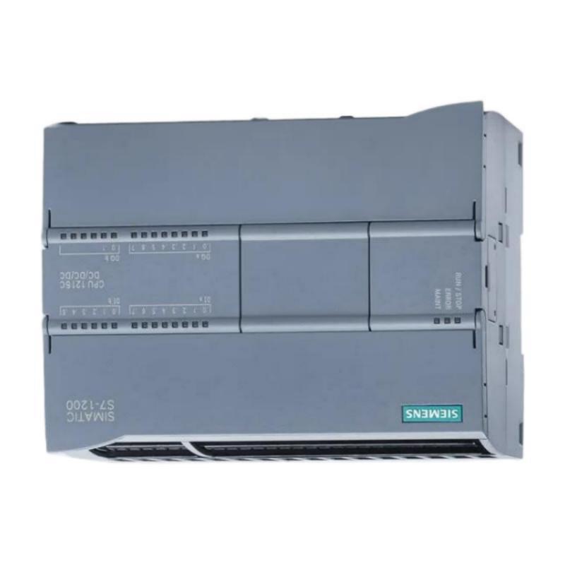
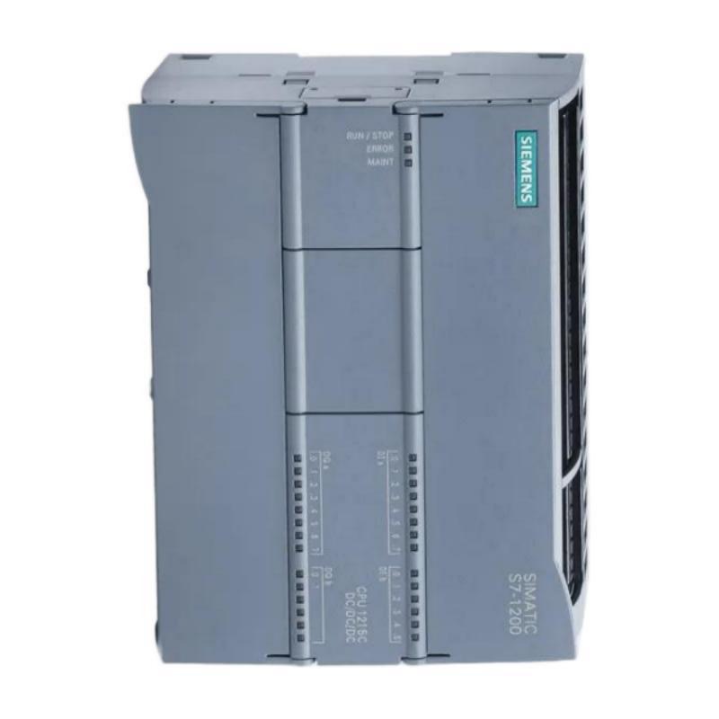
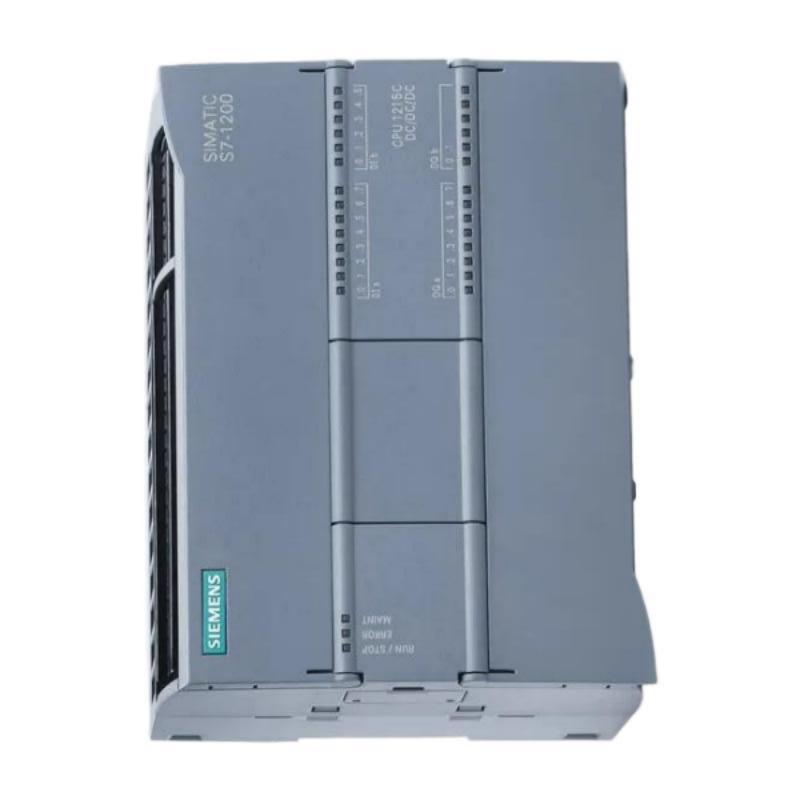
- Siemens
- 6AG1223-1PH32-2XB0
- SIPLUS S7-1200 SB 1223 2DI/2DQ
- Germany
- 45 × 100 × 75 mm
- 0.22kg
- Xiamen, China
- New & In Stock
- T/T, PayPal, Western Union
- 1 Year
- 1-3 Working Days
- DHL, UPS, TNT, FedEx and EMS.
- 24-Hour Service
- COO
- 6
Our advantage

Global Logistics
We have a 10-year logistics and express cooperation agreement, so our products can be shipped to any place in the world.

Brand new and original
Our products are imported in bulk from the place of origin. Because of the cooperative relationship, our products are all original and 100% new.

24-hour service
We provide 7*24 hours service to our customers. We will be there whenever you need us.

Price advantage
All our products are priced very favorably because we have our own warehouse and supply.
| Company Information | |||
| [email protected] | |||
| Mobile | +8615980777398 | ||
| +8615980777398 | |||
| 15980777398 |
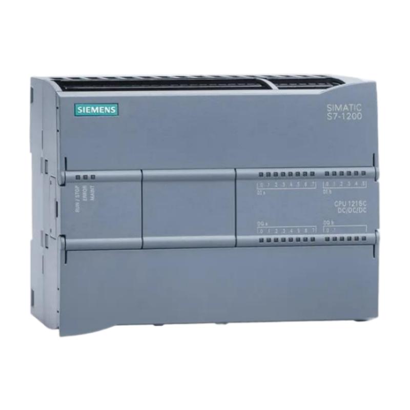
Siemens 6AG1223-1PH32-2XB0 Digital Input/Output Module — Product Overview and Technical Specifications
1. Product Introduction
The Siemens 6AG1223-1PH32-2XB0 is a digital input/output module in the SIPLUS S7-1200 automation product family. It is designed to expand the digital signal-handling capability of a compatible programmable logic controller (PLC), allowing a control system to receive signals from field devices and send switching commands to external equipment.
Digital I/O modules are commonly used between the PLC CPU and devices such as push buttons, selector switches, limit switches, proximity sensors, indicator lamps, relays, contactors, and other control components. By consolidating these connections into one module, the control cabinet can be arranged more clearly, making wiring, commissioning, and maintenance easier to manage.
The SIPLUS designation identifies an environmental variant within the S7-1200 ecosystem. When selecting this module, it is important to confirm the exact electrical configuration, output type, temperature range, and compatibility with the installed CPU. The complete order number should be checked before purchasing or replacing a unit, because modules with similar model numbers may have different output technologies or environmental specifications.
The product is intended for industrial automation applications where reliable digital signal exchange is an important part of machine operation. Its practical value lies in expanding the PLC’s ability to monitor operating conditions, respond to input signals, and control connected devices as part of an automated sequence.
2. Brand and Product Series
| Item | Description |
|---|---|
| Brand | Siemens |
| Product model | 6AG1223-1PH32-2XB0 |
| Product family | SIPLUS S7-1200 |
| Product series | SM 1223 digital input/output module family |
| Product category | PLC digital signal expansion module |
| Main function | Digital signal acquisition and switching control |
| System type | Programmable logic controller automation system |
| Installation environment | Industrial control cabinet or approved mounting arrangement |
| Typical system role | Expansion of CPU digital I/O capacity |
| Main application areas | Machine automation, equipment control, process monitoring, production lines |
| Compatibility requirement | Must be verified against the specific S7-1200 CPU and system configuration |
Model identification note: The model number is similar to other SM 1223 modules, but the exact electrical configuration of 6AG1223-1PH32-2XB0 should be confirmed against its product label or technical datasheet before using the detailed electrical values below for design or replacement. The tables distinguish general application information from specifications that require exact model confirmation.
3. Detailed Technical Specifications
The following specifications describe the module’s identified configuration: 8 digital inputs, 8 relay outputs, a 24 V DC input circuit, and relay switching outputs. These details are useful when planning PLC expansion, selecting field devices, and checking the suitability of the module for an existing control cabinet.
| Parameter | Technical specification |
|---|---|
| Model number | 6AG1223-1PH32-2XB0 |
| Product type | SIPLUS S7-1200 SM 1223 |
| Module function | Digital input and relay output |
| Number of digital inputs | 8 |
| Number of digital outputs | 8 |
| Input signal type | 24 V DC |
| Input configuration | Sink/source compatible |
| Output type | Relay |
| Rated DC supply voltage | 24 V DC |
| Permissible DC supply range | 20.4–28.8 V DC |
| Maximum switching current per relay output | 2 A, subject to load and operating conditions |
| Switching voltage range | 5–30 V DC or 5–250 V AC, subject to the specified load limits |
| Maximum switching power | Up to 30 W DC / 200 W AC, subject to the applicable output ratings |
| Backplane current consumption | Approx. 145 mA at 5 V DC |
| Typical power dissipation | Approx. 5.5 W |
| Input characteristic | IEC 61131 Type 1 |
| Input signal at logic 0 | Up to 5 V DC at 1 mA |
| Input signal at logic 1 | From 15 V DC at 2.5 mA |
| Typical input current at logic 1 | Approx. 4 mA |
| Minimum input current at logic 1 | Approx. 2.5 mA |
| Input grouping | Groups of 2 |
| Configurable input delay | 0.2, 0.4, 0.8, 1.6, 3.2, 6.4 or 12.8 ms |
| Output technology | Electromechanical relay contacts |
| Integrated output short-circuit protection | No |
| Environmental protection feature | Conformal coating |
| Operating temperature | -40°C to +70°C |
| Startup temperature | -25°C minimum startup temperature |
| Mounting arrangement | S7-1200-compatible module mounting |
| Product dimensions (W × H × D) | 45 × 100 × 75 mm |
| Approximate product net weight | 0.222 kg |
| Approximate weight for planning | 0.23 kg |
Important: Relay outputs have different electrical limits for AC and DC loads. The maximum switching current must not be interpreted as permission to switch every voltage and load type at that current. Inductive loads, such as contactor coils and solenoid valves, may require appropriate suppression components.
4. Digital Input Specifications
The digital input section receives binary signals from external devices and passes their states to the PLC. Each input can represent a condition such as a machine guard being closed, a product reaching a sensor, a push button being pressed, or a mechanism reaching its end position.
| Input parameter | Specification |
|---|---|
| Model number | 6AG1223-1PH32-2XB0 |
| Number of inputs | 8 digital inputs |
| Rated input voltage | 24 V DC |
| Permissible module supply range | 20.4–28.8 V DC |
| Input signal type | DC digital signal |
| Input characteristic | IEC 61131 Type 1 |
| Logic 0 reference | Up to 5 V DC at 1 mA |
| Logic 1 reference | From 15 V DC at 2.5 mA |
| Typical current at logic 1 | Approx. 4 mA |
| Minimum current at logic 1 | Approx. 2.5 mA |
| Maximum permissible quiescent current at logic 0 | Approx. 1 mA |
| Input grouping | 2 inputs per group |
| Configurable input delay | 0.2–12.8 ms, using the supported preset values |
| Typical connected devices | Push buttons, proximity switches, limit switches, photoelectric sensors |
| Dimensions (W × H × D) | 45 × 100 × 75 mm |
| Approximate weight | 0.222 kg |
How the Digital Inputs Are Used
Push buttons and selector switches: Operators can use push buttons to start or stop a machine, acknowledge an alarm, or select a manual operating mode. Selector switches can provide local control choices to the PLC.
Position and limit sensing: Limit switches can indicate whether a cylinder, conveyor mechanism, or moving assembly has reached a required position. The PLC can use this information to decide when the next operation should begin.
Proximity and photoelectric sensors: These sensors can detect the presence of a workpiece, the movement of a component, or the arrival of a product at a defined station. The PLC processes the input states according to the control program.
Machine status monitoring: Digital inputs can collect feedback from safety-related status contacts, auxiliary contacts, or equipment condition switches. Safety functions themselves must use appropriately rated safety equipment and an approved safety design; an ordinary digital input alone does not provide a safety-rated function.
5. Digital Relay Output Specifications
The module has eight relay outputs. Unlike transistor outputs, relay outputs use switching contacts, which can be suitable for a wider range of AC and DC control loads when those loads remain within the specified electrical limits.
| Output parameter | Specification |
|---|---|
| Model number | 6AG1223-1PH32-2XB0 |
| Number of outputs | 8 relay outputs |
| Output technology | Electromechanical relay |
| Maximum switching current | 2 A per output under specified conditions |
| DC switching voltage range | 5–30 V DC |
| AC switching voltage range | 5–250 V AC |
| Maximum switching power, DC | Up to 30 W |
| Maximum switching power, AC | Up to 200 W |
| Output isolation characteristics | Relay-contact switching; confirm detailed isolation ratings for the installation |
| Integrated short-circuit protection | No |
| Typical controlled devices | Pilot lamps, interface relays, contactor coils, small control loads |
| Recommended design practice | Verify load current, inrush current, electrical life, and suppression requirements |
| Dimensions (W × H × D) | 45 × 100 × 75 mm |
| Approximate weight | 0.222 kg |
Why Relay Outputs Matter
Relay outputs are useful when the control design requires contact-based switching rather than a transistor output. They can accommodate suitable AC or DC control circuits, allowing one PLC module to serve different types of control equipment.
They are often used to switch interface relays, signal lamps, small solenoids, and contactor control circuits. However, the correct output rating depends on the actual load, switching frequency, and whether the load is resistive, capacitive, or inductive.
Relay contacts are mechanical components, so they have a finite electrical and mechanical service life. Applications involving frequent switching, high inrush current, or large inductive loads should be assessed carefully. An external relay, contactor, or suitable suppression circuit may be appropriate.
6. Environmental and Mechanical Specifications
One of the main reasons to consider the SIPLUS version is its environmental design. The module includes conformal coating and an extended operating-temperature range compared with many standard S7-1200 signal modules.
| Parameter | Specification |
|---|---|
| Model number | 6AG1223-1PH32-2XB0 |
| Environmental product family | SIPLUS S7-1200 |
| Conformal coating | Yes |
| Minimum operating temperature | -40°C |
| Maximum operating temperature | +70°C |
| Minimum startup temperature | -25°C |
| Width | 45 mm |
| Height | 100 mm |
| Depth | 75 mm |
| Dimensions (W × H × D) | 45 × 100 × 75 mm |
| Approximate net weight | 0.222 kg |
| Installation location | Industrial control cabinet or approved enclosure |
| Intended system | Compatible S7-1200 PLC configuration |
| Installation consideration | Maintain suitable ventilation and wiring clearance |
| Environmental design consideration | Confirm humidity, condensation, contamination, and cabinet requirements for the actual site |
The extended temperature range can be helpful in installations where the control cabinet experiences temperature fluctuations or operates in a demanding industrial environment. Conformal coating also provides additional protection for electronic assemblies against certain environmental contaminants.
This does not mean the module can be installed without considering its surroundings. The control cabinet should still be designed to manage heat, moisture, dust, vibration, wiring quality, and electromagnetic interference. The final installation must remain within the applicable product and system requirements.
7. Product Applications
7.1 Machine Automation
In automated machinery, the module can collect operating signals from switches and sensors and send output commands to appropriate control devices. For example, the PLC can detect that a workpiece has arrived at a station, operate an actuator through an interface device, and monitor the resulting machine state.
The eight-input and eight-output arrangement is suitable for compact control tasks where a moderate number of binary signals must be handled in a limited cabinet space.
7.2 Packaging Equipment
Packaging machinery commonly relies on digital signals to detect product position, confirm the state of guards, monitor material movement, and coordinate operating sequences. Relay outputs can be used for suitable control loads, such as indicator circuits and interface relays, while the PLC manages the overall sequence.
For high-speed counting, pulse generation, or very frequent switching, the designer should check whether a different signal module or output technology is more appropriate.
7.3 Conveyor Systems
Conveyor installations use digital signals to monitor product arrival, end-of-line conditions, equipment status, and operator commands. A PLC can combine those signals to determine when a conveyor should run, pause, or transfer a product to another station.
The relay outputs can switch suitable external control circuits. Motor power should normally be handled by correctly rated motor starters, contactors, drives, or other appropriate power equipment rather than being supplied directly through a small PLC relay output.
7.4 Assembly and Production Lines
Assembly lines often need to monitor several stations, each with a group of sensors and control devices. The module can be used where eight inputs and eight relay outputs provide enough signal capacity for a section of the process.
Typical uses include workpiece detection, station-ready signals, operator push buttons, status lamps, and commands to interface devices. Where more signals are needed, additional compatible I/O modules may be required.
7.5 Equipment Status Monitoring
The input channels can monitor the status of suitable auxiliary contacts, local switches, and equipment feedback signals. This can help a PLC program distinguish between a command being issued and the expected equipment state being reached.
For example, a controller may energize a contactor coil through an appropriate interface circuit and then monitor an auxiliary contact to confirm that the contactor has changed state.
7.6 Environmental and Demanding Industrial Installations
The SIPLUS version is worth considering for applications with a broader operating-temperature requirement or where conformal coating is an important design feature. Potential applications include industrial machinery in less temperature-controlled locations and equipment exposed to environmental conditions that must be assessed as part of the overall design.
The module should not be treated as universally suitable for every harsh environment. Chemical exposure, condensation, corrosive gases, vibration, and enclosure protection all require an application-specific assessment.
8. Product Advantages
8.1 Combined Digital Inputs and Outputs
The module combines eight digital inputs and eight relay outputs in one compact unit. This allows a single module to collect external status signals and control suitable switching loads, reducing the need to split a small application across separate input-only and output-only modules.
For machines with a relatively modest number of binary signals, this arrangement can simplify the I/O layout and make the wiring plan easier to understand.
8.2 Relay Switching Flexibility
Relay outputs can switch suitable AC or DC circuits, subject to the module’s ratings. This is useful when the application includes different types of control loads and contact-based switching is preferred.
The actual load must be checked carefully. Voltage, current, inrush, power, load type, and switching frequency all affect whether a relay output is appropriate.
8.3 Extended Environmental Capability
The SIPLUS variant features conformal coating and a specified operating range of -40°C to +70°C, with startup specified down to -25°C. These characteristics can provide additional flexibility when designing systems for challenging temperature conditions.
They are particularly relevant when the control equipment cannot always be kept within a typical indoor ambient-temperature range.
8.4 Compact Installation
With dimensions of approximately 45 × 100 × 75 mm and a net weight of approximately 0.222 kg, the module can be integrated into a compact PLC assembly.
The relatively small form factor helps when cabinet space is limited, although the complete design must still provide adequate wiring space, cooling, separation from noise-generating equipment, and access for maintenance.
8.5 Integration with the S7-1200 Platform
As part of the S7-1200 ecosystem, the module can be considered for compatible PLC configurations that require additional digital signal capacity. The PLC program can use its inputs and outputs as part of a larger sequence involving sensors, actuators, operator commands, and equipment feedback.
The exact CPU, firmware, engineering software, hardware configuration, and electrical supply arrangement should be checked before commissioning.
8.6 Useful for Retrofit and Expansion Projects
For an existing machine, a combined I/O module may provide a practical way to expand the signal count without redesigning the entire control system. This is especially useful when adding a few sensors, status contacts, or relay-switched control circuits.
For replacement work, the complete part number and terminal arrangement should be checked. A similar-looking module may use transistor outputs rather than relay contacts, or may have a different environmental specification.
9. Recommended Related Models
The following models are related to the same S7-1200 digital I/O family or provide a similar function. The best choice depends on the required number of signals, output technology, input voltage, and environmental operating conditions.
Dimensions and weights below are included for planning purposes. Where a figure is approximate or a variant differs, confirm the exact order number before finalizing a cabinet layout.
| Model | Product type and key parameters | Dimensions (W × H × D) | Weight (kg) |
|---|---|---|---|
| 6ES7223-1PH32-0XB0 | Standard SM 1223; 8 digital inputs at 24 V DC and 8 relay outputs; base model associated with the SIPLUS variant | 45 × 100 × 75 mm | Approx. 0.230 |
| 6AG1223-1PH32-4XB0 | SIPLUS SM 1223; 8 DI / 8 relay outputs; environmental variant with a different specified temperature range | 45 × 100 × 75 mm | Approx. 0.230 |
| 6AG1223-1QH32-2XB0 | SIPLUS SM 1223; 8 AC digital inputs and 8 relay outputs; intended for applications requiring AC input signals | Approx. 45 × 100 × 75 mm | Approx. 0.227 |
| 6AG1223-1BH32-2XB0 | SIPLUS SM 1223; 8 digital inputs at 24 V DC and 8 transistor outputs; suitable where electronic switching is preferred | 45 × 100 × 75 mm | Approx. 0.210 |
| 6AG1223-1PL32-2XB0 | SIPLUS SM 1223; 16 digital inputs at 24 V DC and 16 relay outputs; provides a larger signal count | 70 × 100 × 75 mm | Approx. 0.350 |
How to Choose Between These Related Models
– Choose 6ES7223-1PH32-0XB0 when a standard environmental variant with the same general 8 DI / 8 relay arrangement meets the application’s requirements.
– Choose 6AG1223-1PH32-4XB0 when the specific environmental range and protection characteristics of that variant are appropriate for the installation.
– Consider 6AG1223-1QH32-2XB0 when the field input signals are AC rather than 24 V DC. Verify the signal voltage and wiring arrangement before selection.
– Consider 6AG1223-1BH32-2XB0 when transistor outputs meet the load requirements and electronic switching is preferable to relay contacts.
– Consider 6AG1223-1PL32-2XB0 when the project requires more input and output points and relay switching is still appropriate.
These are related choices rather than automatic drop-in replacements. In particular, the input type and output technology must match the field wiring and control design.
10. Five Popular Siemens Models for Broader Automation Applications
The models below are common choices across the S7-1200 automation platform. They perform different functions, so they should be viewed as complementary options rather than direct replacements for the 6AG1223-1PH32-2XB0.
| Model | Product category | Main parameters and typical use | Dimensions (W × H × D) | Weight (kg) |
|---|---|---|---|---|
| 6ES7212-1AE40-0XB0 | S7-1200 CPU 1212C | Compact PLC CPU for smaller control systems; onboard digital I/O and expansion capability depend on the exact CPU variant | Approx. 90 × 100 × 75 mm | Approx. 0.295 |
| 6ES7214-1AG40-0XB0 | S7-1200 CPU 1214C | PLC CPU for more involved machine-control applications; supports system expansion within the platform’s limits | Approx. 110 × 100 × 75 mm | Approx. 0.320 |
| 6ES7221-1BH32-0XB0 | SM 1221 digital input module | 16 digital inputs at 24 V DC; suitable when additional input points are needed without adding output channels | Approx. 45 × 100 × 75 mm | Approx. 0.150–0.200 |
| 6ES7222-1BH32-0XB0 | SM 1222 digital output module | 16 transistor outputs at 24 V DC; suitable for compatible electronic switching loads | Approx. 45 × 100 × 75 mm | Approx. 0.200–0.250 |
| 6ES7231-4HF32-0XB0 | SM 1231 analog input module | Analog signal acquisition for compatible sensors and transmitters; channel configuration and supported signal ranges should be checked | Approx. 45 × 100 × 75 mm | Approx. 0.180 |
Note: The dimensions and weights in this table are indicative planning values for the listed product families and order numbers. Verify exact mechanical data against the selected hardware revision and datasheet before using them for a formal design.
10.1 CPU 1212C — Compact Controller
The CPU 1212C is suited to compact automation tasks where a PLC needs to manage a limited number of inputs and outputs, execute a control program, and communicate with compatible system devices. It can form the central controller for small machinery, simple assembly equipment, and compact process stations.
A separate digital I/O module can be considered when the built-in signal capacity does not meet the requirements. The CPU and expansion modules must be selected as a compatible hardware configuration.
10.2 CPU 1214C — Expanded Control Capability
The CPU 1214C is often considered for machine-control projects that require greater I/O capacity or a more extensive control program than a smaller CPU can comfortably support.
It can be used as the central controller for conveyor systems, production machinery, and equipment with several operating stations. When adding a relay-output module, check the CPU’s supported expansion configuration and the electrical requirements of the connected loads.
10.3 SM 1221 — Digital Input Expansion
An input-only module such as the SM 1221 is useful when the control system needs more sensors, switches, and status signals but does not require additional output points.
It may be a better choice than a combined module when most of the required I/O consists of inputs. The exact input voltage, channel count, and dimensions depend on the model selected.
10.4 SM 1222 — Digital Output Expansion
An output-only module such as the SM 1222 is designed to provide additional digital output points. A transistor-output model can be suitable for compatible DC loads and applications where electronic switching is appropriate.
Transistor outputs are not interchangeable with relay contacts in every application. Before selecting a module, confirm the load type, current requirement, switching frequency, and whether AC switching is needed.
10.5 SM 1231 — Analog Input Expansion
Analog input modules serve a different purpose from digital I/O modules. They can receive supported analog signals from compatible transmitters and sensors, such as signals representing temperature, pressure, level, or flow.
The appropriate module depends on the sensor’s output type, signal range, resolution, and wiring requirements. A digital relay-output module cannot directly replace an analog input module where continuous measurement data is needed.
11. Installation and Wiring Considerations
Correct installation is essential for reliable operation. Even when the module is suitable for the application, wiring errors, inadequate power supplies, incorrect load selection, or poor cabinet design can cause intermittent faults or damage.
11.1 Confirm the Exact Model
Check the complete order number printed on the module and compare it with the intended hardware configuration. The 6AG1223-1PH32-2XB0 is an 8-input, 8-relay-output environmental variant. Do not confuse it with a transistor-output model or a 16-channel-per-direction model.
11.2 Check the 24 V DC Supply
The input section uses a 24 V DC signal arrangement. Confirm that the supply voltage remains within the specified operating range under normal and transient operating conditions.
The power supply must also be sized for the PLC CPU, expansion modules, sensors, and other connected loads. Pay attention to voltage drop in long field cables and to common reference or grounding arrangements.
11.3 Verify Relay Loads
Check each output load against the specified voltage, current, and switching-power limits. The maximum switching current does not override the separate voltage and power limits.
For inductive loads, use an appropriate suppression method where required. Depending on the circuit, this may include a suitable diode, RC network, or other correctly rated suppression component. The choice depends on the load’s AC or DC supply and its switching characteristics.
11.4 Separate Control and Power Wiring
Keep low-level signal wiring appropriately separated from high-current and noise-generating circuits. Use correct terminal identification, suitable wire sizes, proper strain relief, and a consistent wiring-label system.
This makes commissioning easier and reduces the chance of incorrect connections during maintenance.
11.5 Plan for Heat and Accessibility
The module’s compact dimensions help conserve cabinet space, but the installation should still allow for ventilation, cable routing, terminal access, and future servicing.
The control cabinet must be designed for the total heat generated by all installed components, not just the module itself.
11.6 Configure and Test the PLC Program
After installation, verify that the hardware configuration recognizes the correct module. Test each input channel with its intended field device and check each output using a suitable test load.
Before energizing external equipment, confirm the PLC program’s logic, interlocks, startup behavior, and fault response. Any safety-related functions require a suitable safety design and approved safety equipment.
12. Troubleshooting Guide
| Symptom | Possible cause | Recommended check |
|---|---|---|
| Input signal does not change in the PLC | Incorrect wiring, missing field supply, wrong common reference, or faulty sensor | Check the field voltage, wiring, sensor output, and input address |
| Input state is unstable | Electrical interference, poor wiring, loose terminals, or unsuitable sensor signal | Inspect wiring, grounding, shielding, terminal connections, and signal levels |
| Relay output does not switch | Incorrect program logic, output not enabled, faulty wiring, or a damaged relay contact | Check the PLC status, output address, field circuit, and load circuit |
| Relay output switches but the load does not operate | External supply missing, incorrect load wiring, or failed load | Measure the load supply and verify the external circuit |
| Relay contacts wear prematurely | Excessive inrush current, inductive load, or switching frequency beyond the intended duty | Reassess the load, suppression circuit, and switching strategy |
| PLC reports a hardware configuration problem | Wrong module selection, incompatible configuration, or engineering-project mismatch | Check the exact order number and supported CPU configuration |
| Module operates inconsistently at temperature extremes | Installation conditions or power supply outside the required range | Check cabinet temperature, supply stability, and environmental suitability |
| Output circuit repeatedly fails | Load exceeds voltage, current, or switching-power limits | Recalculate the load and use an appropriately rated interface device if necessary |
A systematic troubleshooting approach is more effective than replacing the module immediately. Start by checking the supply, wiring, PLC status, and field-device operation. Then isolate the affected channel and verify whether the issue originates in the PLC program, the module, or the external circuit.
13. Product Selection Summary
The Siemens 6AG1223-1PH32-2XB0 is a SIPLUS S7-1200 SM 1223 digital input/output module with eight 24 V DC digital inputs and eight relay outputs. Its combination of relay switching, conformal coating, and a specified operating range of -40°C to +70°C makes it a candidate for compatible industrial automation systems that need both digital signal acquisition and contact-based output control.
Its main strengths are the combined input/output arrangement, the flexibility of suitable relay-switched AC and DC loads, and the environmental characteristics of the SIPLUS version. The compact size of approximately 45 × 100 × 75 mm and net weight of approximately 0.222 kg also make it relatively easy to accommodate in an appropriately designed control cabinet.
The key selection checks are straightforward: confirm the exact model, verify CPU compatibility, match the 24 V DC input arrangement to the field devices, and ensure every relay load remains within the applicable voltage, current, and switching-power limits.
For an application requiring more I/O points, the 16 DI / 16 relay-output model may be worth considering. For an application requiring only inputs or only outputs, a dedicated input or output module may provide a better fit. Where the control cabinet operates in demanding environmental conditions, the exact SIPLUS temperature and protection specification should be part of the selection process.
Overall, this module is best suited to applications where eight digital input signals and eight relay-switched output circuits meet the system requirements, and where the module’s environmental characteristics align with the installation conditions.