
NewsNEWCENTER
Featured products
Contact Us
Schneider Electric 140AII33010C Installation Guide: Modicon Quantum Intrinsically Safe Current Input Module
2026-10-28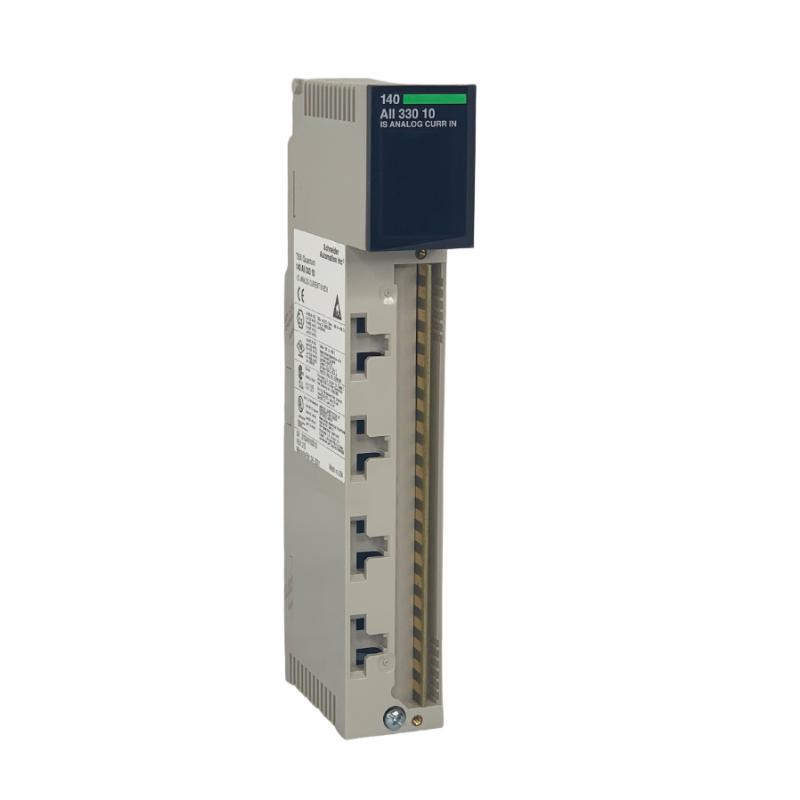
The Schneider Electric 140AII33010C Modicon Quantum intrinsically safe current input module is designed to interface field current signals with industrial automation and process control systems. Featuring eight analog input channels, it supports compatible current signals from field transmitters and is intended for applications requiring intrinsically safe interfacing with instruments installed in hazardous areas.
Correct installation of the Schneider 140AII33010C requires careful attention to rack compatibility, terminal block identification, current input configuration, field wiring, hazardous-area protection requirements, and PLC communication. Because this is an intrinsically safe module, installation must follow the applicable certified wiring diagrams and system entity parameters. Ordinary analog input wiring practices alone are not sufficient to establish a compliant intrinsically safe installation.
Table of Contents
- 1. Product Overview
- 2. Technical Specifications
- 3. Installation Preparation
- 4. Rack Installation and Mounting
- 5. Field Wiring and Terminal Connections
- 6. PLC Configuration and Channel Setup
- 7. Commissioning and Functional Testing
- 8. Integration with Process Control Systems
- 9. Maintenance and Troubleshooting
- 10. Frequently Asked Questions
- 11. Technical Summary
1. Product Overview
The 140AII33010C belongs to Schneider Electric’s Modicon Quantum automation platform. It receives analog current signals from compatible field instruments and makes the corresponding measurement data available to the PLC for process monitoring, control logic, alarms, and supervisory applications.
The module supports eight current input channels. Depending on the selected configuration, supported input ranges include 4–20 mA, 0–20 mA, and 0–25 mA. The module also provides power for compatible intrinsically safe field transmitters, subject to the product’s specified electrical limits and approved installation design.
Typical applications include pressure, flow, level, and other process measurements where compatible current-output instruments must communicate with a Modicon Quantum control system. In hazardous-area installations, the complete field circuit must comply with the relevant intrinsic safety certification and installation requirements.
Key product characteristics
- Eight analog current input channels.
- Configurable current measurement ranges.
- Support for compatible intrinsically safe field instruments.
- Integration with the Modicon Quantum PLC platform.
- Input status monitoring, including broken-wire detection in the 4–20 mA mode.
- Dedicated field wiring terminal strip with keyed connection design.
Product lifecycle note: Schneider Electric lists the 140AII33010C as discontinued, with the end of standard service shown as November 19, 2024. For existing installations, verify the exact hardware reference, revision, availability of technical support, and replacement strategy before planning a new project.
2. Technical Specifications
| Parameter | Specification |
|---|---|
| Manufacturer | Schneider Electric |
| Product family | Modicon Quantum |
| Model | 140AII33010C |
| Product type | Intrinsically safe current input module |
| Number of input channels | 8 |
| Supported current ranges | 4–20 mA, 0–20 mA, 0–25 mA |
| Input impedance | Approximately 100 Ω, according to the specified input terminals |
| Maximum input | 25 mA, internally limited |
| Typical accuracy at 25°C | ±0.05% of full scale |
| Maximum accuracy error at 25°C | ±0.1% of full scale |
| Input filter | Single-pole low-pass filter, approximately 15 Hz cutoff |
| Input update time | Approximately 750 ms for all channels |
| Backplane current requirement | 1.5 A |
| Power dissipation | Approximately 7.5 W |
| Field wiring terminal strip | 140XTS33200, blue, keyed terminal strip |
| Hot swapping | Not permitted under the documented intrinsic safety requirements |
These specifications are provided as a practical reference. Confirm the applicable hardware documentation and certified installation requirements for the exact 140AII33010C revision before selecting power supplies, designing field circuits, or performing commissioning tests.
3. Installation Preparation
Before installing the 140AII33010C, confirm that the PLC rack, power supply, module position, field instruments, and configuration software are compatible with the existing Quantum system.
3.1 Verify the hardware reference
Check the full catalog number on the module label. Do not assume that the 140AII33010C and related references are interchangeable merely because their names are similar. Confirm the suffix, revision, terminal block type, and applicable documentation.
3.2 Inspect the rack and power supply
Verify that the Quantum rack and installed power supply can accommodate the module’s backplane current requirement and thermal dissipation. Check the rack for mechanical damage, contamination, loose connectors, or signs of overheating.
3.3 Confirm the field instruments
Prepare a list of the eight intended field signals. For each channel, record the transmitter tag, measurement variable, current range, field location, and required PLC engineering units.
Confirm that each transmitter is compatible with the module’s electrical characteristics and intrinsically safe circuit design. A field instrument’s current output alone does not establish that it is suitable for direct connection to an intrinsically safe input.
3.4 Review hazardous-area documentation
Before connecting any field circuit, review the applicable certified wiring diagrams, control drawings, and entity parameters for the complete intrinsically safe loop. The permitted combination of module, field instrument, cable, and associated components must be verified by a qualified person.
4. Rack Installation and Mounting
Step 1: Prepare the control cabinet
Ensure that the control cabinet is clean, dry, and suitable for the operating environment. Verify that ventilation and cabinet temperature conditions meet the system requirements. Keep wiring ducts and service access areas organized so that field wiring can be inspected without disturbing unrelated circuits.
Step 2: Isolate the equipment
Follow the plant’s approved shutdown and lockout/tagout procedures before installing or removing the module. Confirm that the relevant equipment is in a safe state. The 140AII33010C must not be hot-swapped; do not remove or insert it while the system is energized.
Step 3: Inspect the module connector
Examine the module’s rear connector and the corresponding rack position. Check for damaged contacts, foreign material, or mechanical obstruction. Handle the module using appropriate electrostatic discharge precautions.
Step 4: Install the module
Align the module with the designated rack position and secure it according to the Modicon Quantum hardware installation instructions. Do not force the module into the rack if the connector or mounting alignment is incorrect.
Step 5: Verify the terminal strip
The module uses a dedicated 40-pin field wiring terminal strip identified as 140XTS33200. The terminal strip is blue to identify the intrinsically safe connection and is mechanically keyed. Confirm the terminal strip coding and module compatibility before fitting it.
Do not rely on wire colors or assumed terminal numbering. Use the certified wiring diagram for the exact model and installation.
5. Field Wiring and Terminal Connections
Field wiring is one of the most important parts of installing the 140AII33010C. Incorrect connections can produce inaccurate readings, open-circuit faults, or a non-compliant hazardous-area installation.
5.1 Prepare the field wiring
- Use the cable type and conductor size specified by the applicable hardware and hazardous-area documentation.
- Use separate shielded, twisted-pair conductors where required by the installation design.
- Identify both ends of every conductor with the corresponding instrument tag and channel number.
- Inspect insulation and terminals for damage before connection.
- Keep intrinsically safe wiring separated from non-intrinsically safe circuits as required by the applicable standards and cabinet design.
5.2 Connect the current input circuits
Connect each field transmitter to its assigned input terminals according to the module’s certified wiring diagram. Verify the intended positive, negative, and signal connections for each channel. Because the module may provide power for compatible intrinsically safe transmitters, the field circuit must be wired exactly as specified rather than treated as an ordinary passive current input.
Never infer terminal positions from a similar module or from a generic 4–20 mA wiring diagram. The correct wiring arrangement depends on the approved configuration for the module and field device.
5.3 Verify the intrinsic safety design
Intrinsic safety depends on limiting electrical energy under normal and specified fault conditions. The module’s certification and entity parameters must be considered together with the field instrument, cable capacitance and inductance, and any associated apparatus.
For applicable certified installations, parameters such as maximum output voltage, current, and power, along with allowable external capacitance and inductance, must be checked against the field device’s permitted input values. Do not use generic calculations or a different module’s parameters to approve the loop.
5.4 Inspect wiring before energization
Check every conductor against the wiring schedule. Confirm terminal tightness using the specified procedure and verify that no stray wire strands, accidental shorts, or unintended ground connections are present. Ensure that the terminal strip is correctly keyed and seated.
6. PLC Configuration and Channel Setup
After the module has been installed and the field wiring inspected, configure the module in the supported Modicon Quantum programming environment. The precise configuration procedure depends on the installed controller, software version, and existing project.
6.1 Configure the module identity and rack position
Verify that the hardware configuration identifies the 140AII33010C in the correct rack and slot. Confirm that the PLC project and installed hardware match. A wrong module selection or incorrect rack address may prevent the controller from interpreting the input data correctly.
6.2 Select the input range for each channel
Configure every channel for the intended signal range. The module supports 4–20 mA, 0–20 mA, and 0–25 mA measurement ranges, with channel ranges configurable according to the supported software and hardware.
For example, a pressure transmitter configured to produce 4–20 mA should use the matching input configuration. If the channel is configured for 0–20 mA, the PLC’s raw value and subsequent engineering-unit conversion may not match the intended measurement.
6.3 Map raw input values to process variables
Assign clear PLC variables to the channel data. Use descriptive names such as Tank_Level_Raw or Line_Pressure_Raw, then implement the appropriate scaling logic to convert the input data into engineering units.
The conversion limits must match the selected module range and data representation. Avoid copying scaling constants from a different input module without verifying the actual raw data format.
6.4 Configure alarm and fault handling
Develop appropriate handling for invalid or missing measurements. In the 4–20 mA mode, the module supports broken-wire detection. Use the documented channel status information to distinguish an input fault from a legitimate process measurement where the application permits this distinction.
For critical process functions, ensure that alarms and protective actions are designed and validated according to the plant’s safety requirements. Do not rely on a single analog value as the sole indication that a hazardous condition is absent.
7. Commissioning and Functional Testing
Commissioning confirms that the installed hardware, field wiring, software configuration, and process display operate as intended. Complete all required electrical and hazardous-area checks before applying power or introducing a field signal.
Step 1: Inspect the complete installation
Verify the rack position, module identity, terminal strip, field cable identification, and compliance with the approved wiring drawings. Confirm that the equipment has been restored to the required safe configuration before energization.
Step 2: Check module status
After authorized energization, inspect the module’s status indicators and PLC diagnostics. The documented indicators include a green Active LED, a red F fault indicator, and individual red channel indicators numbered 1 through 8. Consult the applicable manual for the precise interpretation of each indication.
Step 3: Verify each input channel
Test each channel using the approved commissioning method. Where permitted by the installation design, apply a known signal or compare the connected transmitter output with the corresponding PLC input value. Verify all eight channels individually rather than assuming that one successful channel proves the whole module is operating correctly.
Step 4: Verify the measurement scale
Confirm that the displayed engineering value corresponds to the input signal and the configured range. Check representative points across the intended operating range when the commissioning procedure allows it.
For a 4–20 mA transmitter, for example, verify that the configured lower and upper measurement limits correspond to the intended process limits. The precise raw values must be interpreted using the module’s selected data format and software configuration.
Step 5: Test fault handling
Where authorized and safe, verify the configured response to signal loss and other supported diagnostics using an approved test procedure. Do not deliberately create hazardous-area wiring faults or disconnect energized field circuits unless the documented procedure specifically allows the test.
Step 6: Record commissioning results
Document the module reference, rack location, channel assignments, input ranges, test results, alarm behavior, and any deviations from the approved drawings. These records simplify future maintenance and reduce the risk of configuration errors during replacement.
8. Integration with Process Control Systems
The 140AII33010C provides analog measurement data for compatible Modicon Quantum PLC applications. Its inputs can support monitoring and control functions in industrial facilities where current-output transmitters are installed in approved hazardous-area circuits.
Typical application areas
- Oil and gas: Pressure, flow, and level measurements from compatible field transmitters.
- Chemical processing: Process monitoring in installations that require certified intrinsically safe instrumentation.
- Water and wastewater: Compatible current-output measurements for tank levels, flow rates, and pressure monitoring.
- Industrial manufacturing: Analog feedback used by PLC logic, operator displays, and process alarms.
- Utilities and energy: Monitoring process variables within established control and instrumentation architectures.
The module does not independently provide an HMI, historian, or supervisory network connection. Its measurements are processed by the PLC and made available to other system components through the configured automation architecture.
9. Maintenance and Troubleshooting
After commissioning, periodic inspection helps preserve measurement reliability and identify wiring problems before they cause process interruptions.
| Symptom | Potential cause | Initial action |
|---|---|---|
| Channel reading remains at zero | Open circuit, transmitter power issue, incorrect wiring, or wrong input range | Check the field circuit and channel configuration |
| Red channel indicator is on | Broken wire or out-of-range condition, depending on mode and status | Check channel diagnostics and the applicable manual |
| F fault indicator is on | At least one channel may have a broken-wire or out-of-range condition | Inspect individual channel indications and identify the affected circuit |
| PLC value differs from the instrument | Incorrect scaling, input configuration, or field signal | Compare the transmitter output, raw PLC data, and engineering value |
| All channels are unavailable | Rack configuration, module communication, or system-level issue | Review PLC diagnostics and rack status before replacing hardware |
Preventive maintenance recommendations
- Inspect terminal strips, field cables, and cabinet conditions during scheduled maintenance.
- Keep the module configuration and field wiring drawings up to date.
- Check transmitter calibration according to the plant’s instrument maintenance schedule.
- Review recurring channel faults and record the corrective actions taken.
- Maintain a verified backup of the PLC application and module configuration.
- Follow the certified intrinsic safety procedures whenever working on hazardous-area circuits.
Do not remove or replace the module while energized. Any replacement must be assessed for hardware compatibility, configuration requirements, and compliance with the existing intrinsic safety design.
10. Frequently Asked Questions
What is the Schneider Electric 140AII33010C used for?
It is an eight-channel intrinsically safe current input module for the Modicon Quantum automation platform. It interfaces compatible current-output field transmitters with the PLC for process monitoring and control.
Which input ranges does the module support?
The documented current ranges are 4–20 mA, 0–20 mA, and 0–25 mA. Configure each channel according to the connected instrument and the applicable module documentation.
Does the module provide power to field transmitters?
Yes, the documented design provides power for compatible intrinsically safe transmitters. The field circuit must still comply with the module’s electrical limits and the certified installation design.
Can the 140AII33010C be hot-swapped?
No. The documented intrinsic safety requirements do not permit hot swapping. Follow the required shutdown, isolation, and verification procedures before removing or installing the module.
How can I identify a channel fault?
Inspect the module’s Active, F, and individual channel indicators, then consult the applicable diagnostic definitions. In 4–20 mA mode, broken-wire detection is supported, and the F indicator may report a broken-wire or out-of-range condition on a channel.
Is the 140AII33010C a current-production product?
Schneider Electric lists this reference as discontinued and shows the end of standard service as November 19, 2024. Existing installations may require sourcing through appropriate spare-parts channels and planning a verified migration strategy.
11. Technical Summary
The Schneider Electric 140AII33010C Modicon Quantum intrinsically safe current input module provides eight configurable current input channels for compatible industrial process transmitters. Successful installation depends on correct rack integration, accurate channel configuration, approved field wiring, and verification of the complete intrinsically safe circuit.
For maintenance and engineering teams, the most important steps are to verify the exact hardware reference, follow the certified wiring documentation, configure each channel for its intended current range, test all eight inputs during commissioning, and retain complete records of the installed system.
Because the 140AII33010C is a discontinued product, careful hardware identification and lifecycle planning are especially important when maintaining legacy Modicon Quantum installations. Any replacement or migration should be validated against the existing control architecture and hazardous-area requirements before being placed into service.