

ProductPRODUCT
Featured products
Contact Us
- Siemens
- 1FK7103-2AF71-1RG1
- SIMOTICS S Synchronous Motor
- Germany
- 300 mm x 200 mm x 150 mm
- 28kg
- Xiamen, China
- New & In Stock
- T/T, PayPal, Western Union
- 1 Year
- 1-3 Working Days
- DHL, UPS, TNT, FedEx and EMS.
- 24-Hour Service
- COO
- 6
Our advantage

Global Logistics
We have a 10-year logistics and express cooperation agreement, so our products can be shipped to any place in the world.

Brand new and original
Our products are imported in bulk from the place of origin. Because of the cooperative relationship, our products are all original and 100% new.

24-hour service
We provide 7*24 hours service to our customers. We will be there whenever you need us.

Price advantage
All our products are priced very favorably because we have our own warehouse and supply.
| Company Information | |||
| [email protected] | |||
| Mobile | +8615980777398 | ||
| +8615980777398 | |||
| 15980777398 |
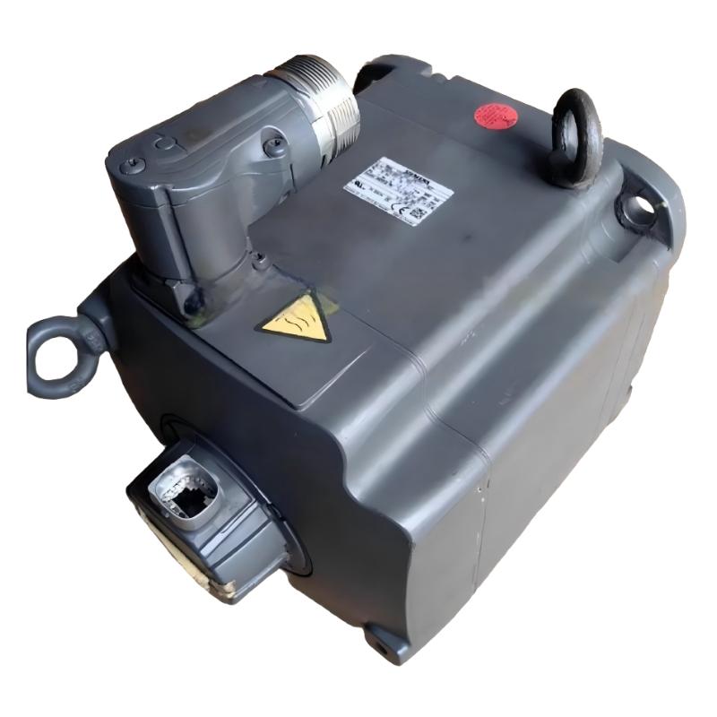
Siemens 1FK7103-2AF71-1RG1 Servo Motor: Technical Specifications, Product Overview, Applications, Advantages, and Related Models
1. Product Overview
The Siemens 1FK7103-2AF71-1RG1 is a model designation associated with the SIMOTICS S-1FK7 servo motor family. This family is designed for industrial motion-control applications where controlled movement, repeatable positioning, and reliable operation are important.
Servo motors are widely used in automated machinery because they can operate under commands from a compatible drive and motion controller. Depending on the system configuration, they can control rotational speed, torque, and position to meet the needs of the production process.
In practical applications, a servo motor may drive a machine-tool axis, packaging mechanism, automated assembly station, material-handling unit, or precision positioning system. Its performance depends not only on the motor itself but also on the drive, feedback device, mechanical transmission, load, and motion-control parameters.
The complete order number matters when selecting or replacing a motor. Models that look similar can have different electrical ratings, feedback arrangements, shaft designs, brake options, or connector configurations. These differences can affect both mechanical installation and compatibility with the existing drive.
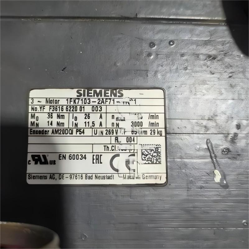
Technical note: The exact rated values, dimensions, and weight for the complete model 1FK7103-2AF71-1RG1 should be confirmed against its matching product documentation or nameplate. The tables below distinguish between general product-family characteristics and values that require model-specific verification.
2. Brand and Product Series
| Parameter | Description |
|---|---|
| Model | 1FK7103-2AF71-1RG1 |
| Brand | Siemens |
| Product family | SIMOTICS |
| Product series | SIMOTICS S-1FK7 |
| Product type | Industrial servo motor |
| General motor category | Servo motor for controlled motion |
| Motor technology | Confirm the exact configuration from the product documentation |
| Main function | Controlled rotational movement in industrial machinery |
| Typical control functions | Position, speed, and torque control, depending on the system |
| Typical system configuration | Motor, compatible drive, feedback arrangement, and controller |
| Typical installation | Automated machinery and industrial production equipment |
| Main selection factors | Torque, speed, feedback, mounting dimensions, shaft design, and weight |
About the SIMOTICS S-1FK7 Series
The SIMOTICS S-1FK7 series is intended for industrial motion-control applications where machine builders need controlled movement and a motor that can be integrated into an automated system.
Motors in this family are used in different machine designs, with the exact configuration determining the electrical interface, mechanical mounting, feedback arrangement, and other installation details.
A typical servo system consists of a motor, a compatible servo drive, a controller, and a mechanical load. The drive regulates the electrical power supplied to the motor, while the controller defines the required movement. The feedback system supports the control process according to the particular motor and drive configuration.
For this reason, selecting a suitable servo motor requires more than comparing nominal power. The motor must also match the required torque, speed, acceleration, load inertia, feedback interface, shaft dimensions, and mounting arrangement.
3. Detailed Technical Parameters
The following specifications describe the identified 1FK7103-2AF71 motor configuration. Ratings should be checked against the actual nameplate and drive configuration before use in a machine design.
| Parameter | Technical specification |
|---|---|
| Model | 1FK7103-2AF71-1RG1 |
| Brand | Siemens |
| Product family | SIMOTICS |
| Product series | SIMOTICS S-1FK7 |
| Motor type | Permanent-magnet synchronous servo motor |
| Construction | Compact design |
| Rated power at optimum operating point | 5.4 kW |
| Rated torque at 100 K temperature rise | 14.0 Nm |
| Rated speed | 3,000 rpm |
| Optimum operating speed | 2,500 rpm |
| Static torque at 60 K temperature rise | 30 Nm |
| Static torque at 100 K temperature rise | 36 Nm |
| Maximum motor torque | 108 Nm, subject to operating limits |
| Rated current | 11.5 A |
| Stall current at 60 K temperature rise | 21 A |
| Stall current at 100 K temperature rise | 26 A |
| Maximum current | 84 A, subject to the applicable configuration |
| Maximum permissible mechanical speed | 5,000 rpm |
| Number of poles | 8 |
| Torque constant | Approximately 1.385 Nm/A |
| Voltage constant at 20°C | 89.5 V per 1,000 rpm |
| Winding resistance at 20°C | Approximately 0.0895 Ω |
| Rotating-field inductance | 2.4 mH |
| Electrical time constant | 27 ms |
| Mechanical time constant | 1.46 ms |
| Thermal time constant | 65 minutes |
| Efficiency | Approximately 93% under the specified test conditions |
| Rotor moment of inertia | Approximately 0.0104 kg·m² |
| Cooling method | Natural cooling |
| Protection rating | IP65 for the identified configuration |
| Mounting arrangement | IM B5; IM V1 and IM V3 arrangements where permitted |
| Shaft height | 100 mm |
| Shaft design | Plain shaft |
| Holding brake | No holding brake in the identified configuration |
| Feedback system | Absolute encoder, AM20DQI configuration |
| Encoder resolution | 20-bit single-turn plus 12-bit multiturn |
| Temperature monitoring | Pt1000 temperature sensor |
| Electrical connections | Rotatable power and signal connectors |
| Net weight (kg) | Approximately 28.5 kg without a holding brake |
| Dimensions (mm) | Exact overall length, width, and height require the matching mechanical drawing |
Understanding the Performance Ratings
The rated torque of 14 Nm at 3,000 rpm describes the motor’s specified continuous operating point under the stated thermal conditions. The maximum torque of 108 Nm is a limiting value, not a torque that should be assumed available continuously.
The 5.4 kW figure refers to the optimum operating point. It should not automatically be treated as the continuous rated output at every speed. Actual power and torque depend on speed, current limits, thermal conditions, and the compatible drive.
The motor’s 5,000 rpm maximum permissible mechanical speed is also a limit rather than a recommendation to operate continuously at that speed. The drive, load, and mechanical transmission must all be suitable for the selected operating point.
4. Dimensions and Weight
The motor’s shaft height is 100 mm, and the identified version has an IM B5 mounting arrangement. The exact flange measurements, shaft dimensions, and overall body dimensions should be taken from the mechanical drawing for the complete order number.
| Mechanical parameter | Specification |
|---|---|
| Model | 1FK7103-2AF71-1RG1 |
| Shaft height | 100 mm |
| Mounting arrangement | IM B5 |
| Other permitted mounting orientations | IM V1 / IM V3, subject to installation requirements |
| Flange size designation | Confirm from the matching dimensional drawing |
| Flange width | Exact value requires drawing confirmation |
| Flange height | Exact value requires drawing confirmation |
| Mounting-hole spacing | Exact value requires drawing confirmation |
| Shaft diameter | Exact value requires drawing confirmation |
| Shaft extension length | Exact value requires drawing confirmation |
| Shaft type | Plain shaft |
| Connector arrangement | Rotatable power and signal connectors |
| Overall motor length | Exact value requires drawing confirmation |
| Overall dimensions (mm) | Exact length × width × height not confirmed |
| Net weight (kg) | Approximately 28.5 kg without a holding brake |
| Brake-related weight | Not applicable to the identified no-brake configuration |
| Cooling clearance | Follow the installation requirements for the exact motor version |
The shaft height and weight are useful reference points, but they are not sufficient to confirm that the motor will fit an existing machine. Before replacing a motor, compare the flange, mounting-hole pattern, shaft diameter, shaft extension, overall length, and connector clearance.
For transport and installation, allow for the weight of any additional coupling, gearbox, mounting hardware, or accessories. If the motor is being purchased for a replacement project, the actual nameplate and mechanical drawing should take priority over a general product-family description.
5. Product Introduction
5.1 Precision Motion Control
The 1FK7103-2AF71-1RG1 belongs to a servo-motor category designed for controlled movement in automated machinery. When connected to a compatible drive and controller, the motor can follow commands for position, speed, and torque according to the system’s configuration.
This is particularly useful when the machine needs to move a component to a defined location, maintain a controlled speed, or coordinate movement with other machine axes.
5.2 Permanent-Magnet Synchronous Design
The identified motor configuration uses permanent-magnet synchronous motor technology. This type of motor is commonly used in industrial servo systems because it can provide controlled torque and speed when operated with an appropriate drive.
Its operating characteristics depend on the winding design, current supplied by the drive, motor temperature, and load. Correct motor data and drive configuration are important for achieving stable performance.
5.3 Absolute Encoder Feedback
The identified AM20DQI feedback configuration provides 20-bit single-turn resolution and 12-bit multiturn information. This feedback arrangement supports position measurement and is intended to work with a compatible control system.
The feedback interface must match the selected drive. A motor with the wrong feedback configuration may not be suitable for an existing system, even if its mounting dimensions are similar.
5.4 Natural Cooling
The motor uses natural cooling in the identified configuration. Its thermal performance therefore depends on the specified operating conditions, surrounding temperature, installation arrangement, and duty cycle.
When a motor operates under high load or repeatedly accelerates and decelerates, its heat generation must be considered during sizing. Operating outside the permitted thermal limits may shorten service life or trigger protective shutdowns.
5.5 Mechanical Integration
The IM B5 mounting arrangement and 100 mm shaft height provide useful starting points for mechanical planning. The plain shaft requires a compatible coupling or transmission arrangement.
Correct alignment is important. Misalignment can increase bearing loads, vibration, and mechanical wear. The motor should be mounted securely, and the driven mechanism should be checked for excessive friction or backlash.
6. Main Applications
6.1 CNC Machine Tools
Servo motors are commonly used for controlled feed movement, positioning axes, and other machine-tool functions. The motor can support repeatable movement when the drive, feedback system, and mechanical transmission are correctly matched.
The required torque depends on the moving mass, cutting forces, acceleration, transmission efficiency, and desired positioning performance. The motor should be sized using the complete operating cycle rather than the rated power alone.
6.2 Packaging Machinery
Packaging equipment often requires precise film feeding, product indexing, cutting, sealing, and synchronized movement between different sections of a machine.
A servo motor can help maintain consistent travel distances and repeatable cycle timing. In high-speed packaging applications, acceleration, peak torque, and thermal loading are particularly important selection factors.
6.3 Automated Assembly Equipment
Assembly machinery may need to position components before pressing, fastening, insertion, inspection, or transfer operations. Servo-controlled movement can support repeatability and coordinated motion between stations.
The accuracy achieved by the complete system also depends on the machine structure, transmission backlash, sensor placement, controller settings, and mechanical condition.
6.4 Material Handling and Transfer Systems
Servo motors can drive positioning tables, transfer mechanisms, product feeders, and automated loading equipment.
For these applications, the load mass, movement distance, acceleration, stopping requirements, and gearbox ratio should be evaluated before choosing the motor. Vertical-axis applications require additional consideration of load holding and machine safety.
6.5 Printing and Converting Equipment
Printing and converting machinery may use servo motion to control material feeding, roller synchronization, indexing, and cutting positions.
The motor’s suitability depends on the required speed profile, load variation, and coordination between the machine’s different sections. A properly configured servo system can help make repeated movements more consistent.
6.6 Special-Purpose Machinery
Custom-built machinery often combines several controlled movements within a single production cycle. Servo motors may be used for rotary tables, linear positioning axes, automated feeders, or specialized mechanisms.
For these applications, the most important factors are the required torque, speed, acceleration, mounting arrangement, feedback compatibility, and the machine’s overall operating profile.
7. Main Product Advantages
7.1 Controlled Positioning
When used with compatible feedback and a properly configured drive, the motor can support repeatable positioning. This is valuable in automated systems where a component must stop at a defined location or follow a specific movement sequence.
7.2 Responsive Motion Control
The servo drive can control acceleration and deceleration according to the selected motion profile. Actual response depends on the motor’s capabilities, the drive, load inertia, and mechanical stiffness.
7.3 Useful Torque Characteristics
The identified motor configuration has a rated torque of 14 Nm and a specified static torque of 30 Nm at a 60 K temperature rise or 36 Nm at a 100 K temperature rise.
These values describe different operating conditions and should not be treated as interchangeable. Correct sizing must consider both continuous load requirements and short-duration torque demand.
7.4 Absolute Position Feedback
The identified encoder configuration provides single-turn and multiturn position information. This can be useful in applications that require position measurement and controlled motion across multiple operating cycles.
The exact feedback interface and commissioning requirements must be checked against the compatible drive.
7.5 Compact Industrial Design
The motor’s compact construction and 100 mm shaft height can be useful in machine designs where installation space matters. The final fit still depends on the flange, shaft, overall length, connector arrangement, and required service clearance.
7.6 Integration into Automated Systems
A servo motor can form part of a larger motion-control system that includes a controller, drive, sensors, and mechanical transmission. This makes it suitable for automated machinery that needs controlled and repeatable movement.
7.7 Industrial Protection
The identified configuration has an IP65 protection rating. This rating should be interpreted according to the motor’s specified installation conditions, including the connector arrangement and any relevant shaft or mounting limitations.
It does not mean that the motor can be installed in every environment without further assessment.
8. Five Related Models from the Same Series
The following models are candidates for technical comparison within the SIMOTICS S-1FK7 family. The configurations differ, so none should be considered a direct substitute until the complete order number and matching specifications have been checked.
| Model | Product series | General application | Rated power / torque | Rated speed | Dimensions (mm) | Weight (kg) |
|---|---|---|---|---|---|---|
| 1FK7100-2AF71-1RG1 | SIMOTICS S-1FK7 | Industrial positioning and automation | Approximately 3.8 kW; 18 Nm as a family configuration reference | 3,000 rpm for the referenced configuration | Exact drawing required | Approximately 28 kg; verify exact version |
| 1FK7103-2AF71-1QH1 | SIMOTICS S-1FK7 | Servo-driven machinery | Approximately 4.4 kW; 36 Nm static torque at 100 K for the referenced configuration | 3,000 rpm | Exact drawing required | Approximately 28.8 kg |
| 1FK7103-2AF71-1QG0 | SIMOTICS S-1FK7 | Industrial motion control | Compare rated torque, feedback, and brake configuration | 3,000 rpm for the referenced motor configuration | Exact drawing required | Approximately 28.5 kg |
| 1FK7103-2AF71-1EG1 | SIMOTICS S-1FK7 | Positioning and automation axes | 14 Nm rated torque for the referenced 1FK7103-2AF71 configuration | 3,000 rpm | Exact drawing required | Approximately 28.5 kg |
| 1FK7103-2AF71-1RG2 | SIMOTICS S-1FK7 | Servo-controlled industrial machinery | 14 Nm rated torque for the referenced motor configuration | 3,000 rpm | Exact drawing required | Approximately 28.5 kg |
The values in this comparison table are preliminary references for the listed configurations. Feedback type, brake presence, connector details, protection features, and final dimensions must be confirmed for the exact model before ordering.
9. Five Additional Siemens Models for Comparison
These models provide additional options for evaluating different servo motor configurations. They are not all equivalent in power, torque, or mechanical size, so selection should be based on the requirements of the application.
| Model | Product family | General application | Key parameters to evaluate | Dimensions (mm) | Weight (kg) |
|---|---|---|---|---|---|
| 1FK7042-5AF71-1EG5 | SIMOTICS S-1FK7 | Compact servo positioning | Rated torque, speed, current, feedback, shaft | Exact drawing required | Exact version required |
| 1FK7063-5AF71-1EG5 | SIMOTICS S-1FK7 | Automated machine axes | Torque, speed, motor inertia, mounting | Exact drawing required | Exact version required |
| 1FK7083-5AF71-1DG5 | SIMOTICS S-1FK7 | Industrial motion control | Electrical ratings, feedback, shaft and brake | Exact drawing required | Exact version required |
| 1FT7064-series motor | SIMOTICS S-1FT7 | Industrial servo applications | Exact order number, torque, cooling, feedback | Exact drawing required | Exact version required |
| 1PH8-series motor | SIMOTICS S-1PH8 | Industrial drive applications | Exact order number, power, speed, cooling and mounting | Exact drawing required | Exact version required |
The last two entries identify product families rather than complete order numbers. A specific order number is necessary before exact torque, speed, dimensions, and weight can be established.
10. Model Selection Guide
| Selection factor | What to compare | Why it matters |
|---|---|---|
| Rated torque | Continuous torque required by the machine | Determines whether the motor can sustain the load |
| Peak torque | Permitted peak torque and duration | Influences acceleration and short-duration load demands |
| Rated speed | Required operating speed | Ensures the motor suits the motion profile |
| Rated power | Mechanical output required | Helps establish motor capacity |
| Rated current | Motor current and compatible drive rating | Prevents electrical mismatch |
| Feedback system | Encoder type and drive interface | Determines control-system compatibility |
| Brake | Presence, voltage, and holding capability | Important for applications requiring load holding |
| Shaft dimensions | Diameter, extension, and coupling requirements | Ensures mechanical compatibility |
| Flange dimensions | Mounting pattern and geometry | Determines whether the motor physically fits |
| Overall length | Motor body and fitted options | Prevents interference with adjacent components |
| Dimensions (mm) | Verified length, width, height, and mounting measurements | Essential for replacement and machine design |
| Weight (kg) | Exact net weight for the selected configuration | Important for transport, installation, and support design |
| Protection rating | Required protection for the installation environment | Helps determine environmental suitability |
| Drive compatibility | Supported motor data and feedback arrangement | Necessary for reliable commissioning |
For an existing machine, start with the complete model number of the installed motor. If an exact replacement is unavailable, compare the mechanical and electrical specifications carefully before considering a different model.
11. Installation and Commissioning
11.1 Mechanical Installation
Check the mounting flange, shaft dimensions, coupling, and driven mechanism before installation. Ensure that the mounting surfaces are clean and that the motor can be aligned correctly.
Poor alignment can increase vibration and bearing loads. The motor should be securely mounted, and the driven mechanism should move freely within its intended operating range.
11.2 Electrical Connections
Verify the motor’s electrical specifications and connector arrangement before connecting it to a drive. Confirm that the feedback interface is compatible with the selected drive and controller.
Electrical work should be performed by qualified personnel using appropriate isolation and safety procedures.
11.3 Drive Configuration
Configure the drive for the exact motor model and feedback system. Incorrect motor data, current limits, or control settings can cause faults or unstable motion.
Perform initial tests with conservative motion settings, and verify the motor’s response before operating the machine at normal production speed.
11.4 Brake and Load-Holding Requirements
The identified 1RG1 configuration is specified without a holding brake. If the application requires a brake, do not assume that this motor provides one.
For vertical axes or suspended loads, the complete machine must have suitable provisions to prevent uncontrolled movement. A motor brake, where fitted, is not a replacement for the machine’s required safety measures.
11.5 Initial Operation
During commissioning, observe the motor’s acceleration, deceleration, positioning behavior, vibration, temperature, and drive fault indications.
If abnormal noise, overheating, or repeated faults occur, investigate the mechanical load, alignment, wiring, feedback configuration, and drive settings before concluding that the motor is defective.
12. Maintenance and Troubleshooting
| Problem | Possible cause | Recommended checks |
|---|---|---|
| Motor does not start | Power supply issue, drive fault, or incorrect configuration | Check the drive status, wiring, and motor data |
| Positioning is inaccurate | Feedback issue, mechanical play, or poor tuning | Inspect feedback connections, coupling, transmission, and drive settings |
| Excessive vibration | Misalignment, resonance, or mechanical wear | Check the mounting, shaft alignment, and driven mechanism |
| Motor becomes too hot | Excessive load, frequent acceleration, or insufficient cooling clearance | Review the duty cycle, load, and installation conditions |
| Overcurrent fault | Mechanical obstruction, incorrect settings, or electrical fault | Inspect the mechanism, wiring, and configured limits |
| Feedback fault | Damaged cable, loose connection, or incompatible interface | Inspect the feedback cable and verify drive compatibility |
| Unusual mechanical noise | Bearing wear, coupling problems, or excessive load | Inspect the mechanical system and stop operation if necessary |
| Inconsistent operation | Incorrect parameters or varying load conditions | Review the motion profile and system configuration |
A structured troubleshooting process is usually more effective than immediately replacing the motor. The drive’s fault information, mechanical transmission, feedback cable, and actual load should all be checked.
13. Purchasing Checklist
Before ordering the Siemens 1FK7103-2AF71-1RG1 or selecting an alternative, confirm the following points.
14. Final Product Summary
The Siemens 1FK7103-2AF71-1RG1 is a permanent-magnet synchronous servo motor in the SIMOTICS S-1FK7 family. The identified configuration has a rated speed of 3,000 rpm, rated torque of 14 Nm, rated current of approximately 11.5 A, natural cooling, IP65 protection, a 100 mm shaft height, an absolute encoder, and no holding brake.
Its intended applications include CNC machinery, packaging equipment, automated assembly, material handling, printing and converting machinery, and other industrial motion-control systems.
The motor’s main practical strengths are its controlled motion capability, feedback-based positioning, and suitability for integration into automated machinery. Actual performance depends on correct motor sizing, drive compatibility, mechanical installation, and commissioning.
For replacement projects, verify the full order number, feedback interface, brake arrangement, shaft and flange dimensions, overall dimensions, and net weight before purchase. Related models should be treated as comparison candidates until their exact electrical and mechanical specifications have been confirmed.