

ProductPRODUCT
Featured products
Contact Us
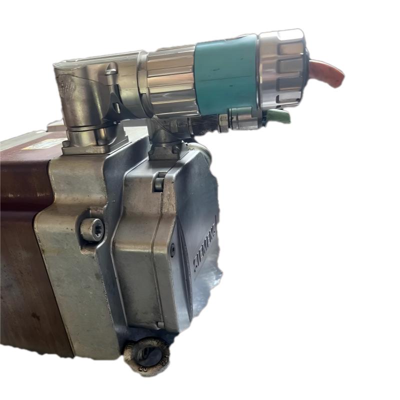
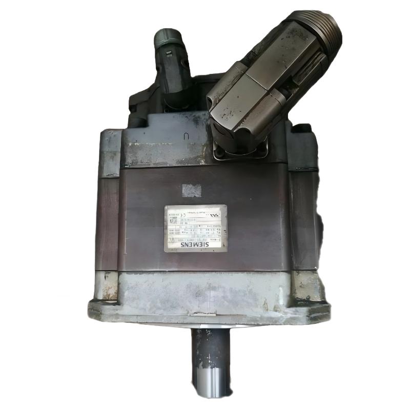
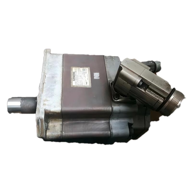
- Siemens
- 1FK7101-5AF71-1SG0
- SIMOTICS S Synchronous Motor
- Germany
- 300 mm x 200 mm x 150 mm
- 21kg
- Xiamen, China
- New & In Stock
- T/T, PayPal, Western Union
- 1 Year
- 1-3 Working Days
- DHL, UPS, TNT, FedEx and EMS.
- 24-Hour Service
- COO
- 7
Our advantage

Global Logistics
We have a 10-year logistics and express cooperation agreement, so our products can be shipped to any place in the world.

Brand new and original
Our products are imported in bulk from the place of origin. Because of the cooperative relationship, our products are all original and 100% new.

24-hour service
We provide 7*24 hours service to our customers. We will be there whenever you need us.

Price advantage
All our products are priced very favorably because we have our own warehouse and supply.
| Company Information | |||
| [email protected] | |||
| Mobile | +8615980777398 | ||
| +8615980777398 | |||
| 15980777398 |
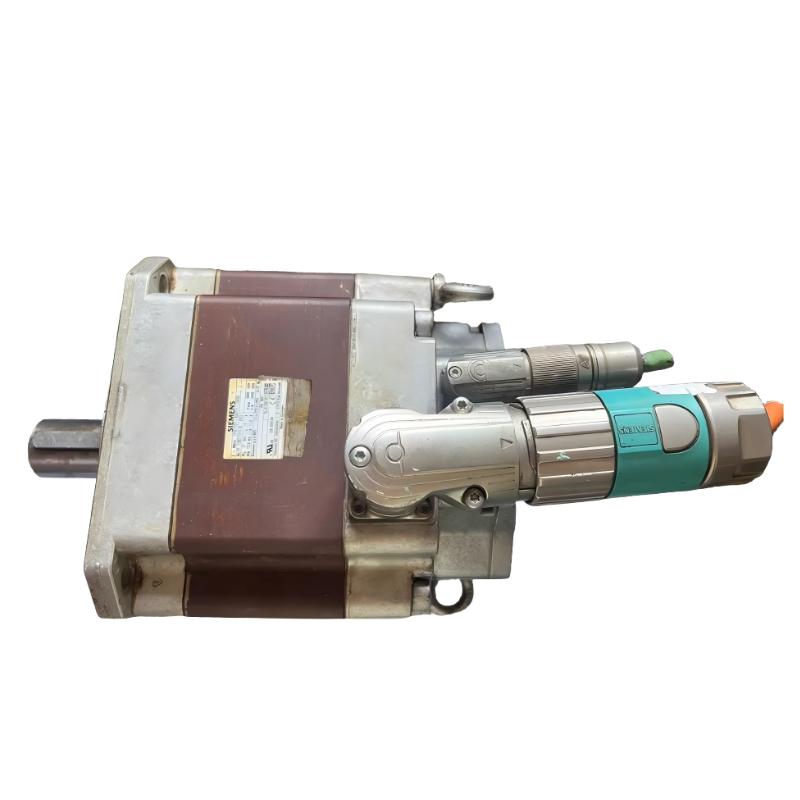
Siemens 1FK7101-5AF71-1SG0 Servo Motor: Technical Specifications, Product Description, Applications, Advantages, and Model Comparison
1. Product Overview
The Siemens 1FK7101-5AF71-1SG0 is a model designation associated with the 1FK industrial servo motor family. This type of motor is intended for motion-control applications in which accurate positioning, controlled speed, repeatable movement, and reliable integration with automated machinery are important.
Industrial servo motors are commonly used in CNC equipment, automated production lines, packaging machinery, assembly systems, material-handling equipment, and specialized manufacturing machines. In these applications, the motor works with a compatible servo drive and control system to convert electrical commands into controlled mechanical movement.
The complete model designation is important because different configurations within the same motor family can have different winding characteristics, feedback devices, shaft arrangements, mounting interfaces, and other technical details.
The 1FK7101-5AF71-1SG0 should therefore be identified by its full ordering designation rather than by the general 1FK series name alone.
This product guide covers the motor’s identification, technical parameters, construction, operating principles, industrial applications, advantages, installation requirements, and maintenance considerations. It also provides two comparison tables containing five related model candidates and five additional model candidates for broader evaluation.
Technical accuracy note: The exact rated power, rated torque, rated speed, overall dimensions, and net weight of the complete 1FK7101-5AF71-1SG0 configuration cannot be established reliably from the model designation alone. These values must be confirmed using the exact motor nameplate or technical documentation. To avoid misleading specifications, unconfirmed numerical values are identified explicitly rather than estimated.
2. Basic Product Information
| Parameter | Technical Information |
|---|---|
| Model | 1FK7101-5AF71-1SG0 |
| Brand | Siemens |
| Product Family | SIMOTICS |
| Product Series | 1FK7 Compact |
| Product Type | Synchronous servo motor |
| Motor Technology | Permanent-magnet synchronous motor |
| Phase | Three-phase |
| Cooling Method | Natural cooling |
| Mounting Arrangement | IM B5 flange mounting; verify the exact configuration |
| Shaft Height | 100 mm |
| Rated Power | Approximately 4.85–4.9 kW |
| Rated Speed | 3,000 rpm |
| Rated Torque | Approximately 15.5 Nm under the stated 100 K temperature-rise rating |
| Static Torque | Approximately 27 Nm under the stated 100 K temperature-rise rating |
| Rated Current | Approximately 11.8 A; confirm against the motor nameplate |
| Number of Pole Pairs | 4 |
| Rotor Moment of Inertia | Approximately 79.9 × 10⁻⁴ kg·m² for the corresponding motor configuration |
| Maximum Permissible Mechanical Speed | Configuration-dependent; some corresponding configurations specify 5,000 rpm |
| Feedback System | Exact feedback and interface configuration must be confirmed for the SG0 order code |
| Holding Brake | Must be confirmed for the exact configuration |
| Shaft Design | Confirm the shaft-end design and tolerances from the dimensional drawing |
| Protection Rating | Must be confirmed for the exact SG0 configuration |
| Approximate Motor Weight | Approximately 21 kg for the corresponding motor configuration; verify the exact variant |
| Overall Dimensions | Exact length, width, and height require the corresponding dimensional drawing |
| Flange Dimensions | Confirm from the exact mechanical drawing |
| Drive Compatibility | Requires a compatible servo drive and feedback interface |
| Typical Application | Industrial motion control, automated machinery, positioning systems, and production equipment |
The electrical figures above are useful for preliminary engineering assessment, but they should not replace the rating-plate values for the exact motor.
2.1 Understanding the Rated Torque
One important point when evaluating this motor is the difference between rated torque and static or standstill torque.
Rated torque describes the torque available under the specified operating and thermal conditions. It is a key parameter when determining whether the motor can continuously drive the machine’s load.
Static torque describes a specified standstill torque condition. It should not be interpreted as the torque the motor can deliver continuously at every speed.
For this model family, the approximately 15.5 Nm rated torque and approximately 27 Nm static torque are different operating specifications. Both are useful, but they serve different purposes in motor selection.
The actual available torque also depends on the selected drive, current limits, speed, cooling conditions, and duty cycle.
2.2 Understanding the Rated Power
A motor’s mechanical output power is related to torque and rotational speed.
The relationship is:
\[ P=\frac{T \times n}{9550} \]
Where:
- \(P\) is mechanical power in kilowatts.
- \(T\) is torque in newton-metres.
- \(n\) is rotational speed in revolutions per minute.
Using a rated torque of 15.5 Nm and a rotational speed of 3,000 rpm:
\[ P=\frac{15.5\times3000}{9550}\approx4.87\text{ kW} \]
This is consistent with an approximately 4.85–4.9 kW motor rating.
The relationship is useful when checking the consistency of a motor’s power, torque, and speed specifications. It does not mean that the motor can maintain its rated torque at every possible speed.
3. Product Dimensions and Weight
Dimensions and weight are essential when selecting a motor for a new machine or replacing an existing unit.
For the 1FK7101-5AF71-1SG0, the 100 mm shaft-height designation helps establish the general mechanical size category. However, it does not provide every dimension required for installation.
The following table identifies the relevant dimensions and the information needed for engineering approval.
| Parameter | Value or Status | Unit | Engineering Purpose |
|---|---|---|---|
| Model | 1FK7101-5AF71-1SG0 | — | Identifies the complete motor configuration |
| Shaft Height | 100 | mm | Establishes the shaft centreline relative to the mounting surface |
| Overall Length | Requires confirmation | mm | Determines axial installation space |
| Overall Height | Requires confirmation | mm | Determines vertical clearance |
| Overall Width or Housing Diameter | Requires confirmation | mm | Determines lateral clearance |
| Flange Height | Requires confirmation | mm | Establishes mounting compatibility |
| Flange Width or Diameter | Requires confirmation | mm | Establishes mounting compatibility |
| Mounting-Hole Spacing | Requires confirmation | mm | Determines bolt alignment |
| Mounting-Hole Diameter | Requires confirmation | mm | Determines fastener selection |
| Shaft Diameter | Requires confirmation | mm | Determines coupling compatibility |
| Shaft Extension Length | Requires confirmation | mm | Determines available coupling engagement |
| Connector Clearance | Requires confirmation | mm | Prevents interference with surrounding machinery |
| Net Motor Weight | Approximately 21 | kg | Preliminary handling and structural assessment |
| Shipping Weight | Requires confirmation | kg | Transport and packaging calculations |
Dimension and weight note: The approximately 21 kg figure is a preliminary reference for the corresponding motor configuration, not a guaranteed shipping weight or a substitute for the exact SG0 specification. Overall dimensions and shaft measurements must be taken from the correct dimensional drawing.
When replacing an existing motor, the installation should not be approved based on shaft height alone. The flange, shaft extension, mounting holes, connector orientation, and available clearance must also match.
4. Detailed Product Description
4.1 General Product Description
The 1FK7101-5AF71-1SG0 belongs to the SIMOTICS S-1FK7 Compact synchronous servo motor family.
Its purpose is to convert electrical energy into controlled rotational motion for industrial automation equipment.
A servo motor is generally selected when a machine requires more precise movement control than a simple uncontrolled motor arrangement can provide. Typical requirements include accurate positioning, repeatable cycles, controlled acceleration, coordinated movement between axes, and consistent operation under changing loads.
In a typical installation, the motor operates with a compatible servo drive and a machine controller.
The controller generates the required motion commands, while the drive regulates the electrical power supplied to the motor. Where the selected feedback arrangement supports closed-loop operation, feedback information is used to regulate the motor’s movement and detect deviations from the commanded position or speed.
This combination allows the motor to form part of a larger machine-control system.
The exact performance of the 1FK7101-5AF71-1SG0 depends on its electrical configuration, feedback interface, drive selection, mechanical load, and installation conditions.
4.2 Motor Construction
A permanent-magnet synchronous servo motor generally contains several principal components.
Stator assembly
The stator contains the electrical windings that generate a rotating magnetic field when supplied with controlled electrical power.
The design of the stator and windings influences current requirements, torque characteristics, thermal behaviour, and the motor’s operating range.
Rotor assembly
The rotor contains permanent magnets that interact with the magnetic field produced by the stator.
This interaction generates rotational torque.
The rotor’s inertia affects the effort required to accelerate and decelerate the motor. This is particularly important in applications involving frequent starts, stops, reversals, and rapid positioning.
Shaft and bearings
The shaft transfers rotational force to the driven equipment.
The bearings support the rotating assembly and help maintain the required mechanical alignment.
Correct coupling alignment and appropriate shaft loading are important for maintaining reliability.
Feedback system
The feedback arrangement provides information used by the drive to regulate movement when operating in a feedback-controlled configuration.
The exact feedback type and interface must be confirmed for the SG0 model.
Electrical connections
The motor’s electrical connections carry power and, where applicable, feedback signals.
The correct cables and connection arrangement depend on the motor configuration and compatible drive.
4.3 Natural Cooling
Natural cooling means that the motor relies on its designed heat-dissipation path rather than requiring a dedicated forced-air cooling system as its primary cooling method.
The motor still needs sufficient surrounding space and appropriate ambient conditions to dissipate heat.
Installation in a confined enclosure, operation at a high duty cycle, or exposure to elevated ambient temperatures can affect thermal performance.
The motor must therefore be selected and installed according to its specified thermal limits.
4.4 Flange-Mounted Design
The IM B5 mounting designation generally refers to a flange-mounted motor arrangement.
This type of mounting is useful when the motor must attach directly to a machine housing, gearbox, mounting plate, or other mechanical structure designed for flange installation.
However, the mounting designation does not establish that every motor with an IM B5 arrangement will fit the same machine.
The flange dimensions, shaft geometry, fastener locations, and available clearance must all be checked.
4.5 Feedback and Drive Integration
Servo motors are normally integrated with drives designed to support the motor’s electrical and feedback characteristics.
The feedback interface is particularly important because a drive must be able to interpret the feedback information correctly.
The full model designation 1FK7101-5AF71-1SG0 should be checked against the drive configuration before installation.
Do not assume that the motor’s feedback interface, connector arrangement, or holding-brake configuration is identical to that of another 1FK7 model.
5. Product Applications
The 1FK7101-5AF71-1SG0 is intended for consideration in industrial motion-control systems. Its approximately 4.85–4.9 kW power class and 3,000 rpm rated speed make torque, speed, acceleration, and load inertia important factors when assessing an application.
The following examples describe common industrial uses for servo motors of this type. Actual suitability must be established against the motor’s complete technical specifications and the machine’s operating requirements.
5.1 CNC Machine Tools
CNC machinery requires controlled movement to position tools and workpieces accurately.
Servo motors may be used in feed axes, auxiliary positioning mechanisms, and other machine movements where a programmed position or speed must be maintained.
Typical requirements include:
- Repeatable positioning.
- Controlled acceleration and deceleration.
- Stable operation under changing loads.
- Coordinated motion between multiple axes.
- Reliable integration with the machine controller.
When selecting a motor for CNC equipment, engineers should calculate the torque required by the mechanical transmission and consider the acceleration profile, load inertia, operating speed, and duty cycle.
The motor’s mounting interface must also match the ballscrew, gearbox, coupling, or other transmission arrangement.
5.2 Packaging Machinery
Packaging equipment often performs repeated operations involving product feeding, film movement, sealing, cutting, labeling, and transfer.
Servo motors can control these movements according to the programmed production sequence.
Potential applications include:
- Film-feeding mechanisms.
- Packaging-material positioning.
- Cutting and indexing units.
- Label application.
- Product-transfer mechanisms.
- Synchronized conveyor movements.
In these applications, consistent cycle timing and repeatable movement can be more important than maximum speed alone.
The selected motor must provide sufficient torque throughout the required operating cycle, including acceleration and deceleration.
5.3 Automated Assembly Equipment
Automated assembly machinery uses controlled movement to position components before fastening, inserting, pressing, or joining operations.
Servo motors can provide programmable movement for positioning tables, fixtures, transfer mechanisms, and other machine axes.
The principal benefits are controlled movement and the ability to repeat a programmed operation.
For applications requiring a specific insertion force or pressing force, additional mechanical calculations and force-monitoring functions may be necessary.
Motor torque alone does not establish the permissible force at the workpiece. Transmission ratios, mechanical geometry, structural strength, and control strategy must also be considered.
5.4 Material Handling Systems
Servo motors can be used in automated material-handling equipment to move components between defined positions.
Potential applications include transfer mechanisms, indexing tables, pick-and-place systems, and positioning equipment.
The motor’s required performance depends on:
- Payload mass.
- Travel distance.
- Required acceleration.
- Transmission efficiency.
- Operating speed.
- Cycle frequency.
- Positioning requirements.
For vertical axes, the design must account for gravitational loading and safe behaviour during power loss.
If the application requires a holding brake, the exact motor configuration must be checked to establish whether a suitable brake is fitted.
5.5 Printing and Converting Machinery
Printing, cutting, laminating, and converting equipment often uses multiple coordinated axes.
Servo motors may control feed rollers, cutting mechanisms, indexing systems, and other components requiring synchronized motion.
A suitable servo system can help maintain repeatable movement and coordinate different stages of the production process.
The correct motor size depends on the driven mechanism’s inertia, required torque, operating speed, and production cycle.
5.6 Automated Production Lines
Automated production lines use motors to position parts, operate transfer mechanisms, and coordinate machine operations.
A servo motor may be suitable for an individual positioning axis or another mechanism requiring programmable movement.
The system can be designed to follow different motion profiles, provided the selected controller and drive support the required functions.
For a production-line application, the motor should be evaluated as part of the complete system rather than as an isolated component.
5.7 Special-Purpose Industrial Machinery
Custom industrial machinery may require a combination of rotational movement, positioning, and synchronized motion.
Examples include specialized assembly stations, automated inspection fixtures, indexing equipment, and custom manufacturing systems.
In these applications, the motor should be selected according to the actual mechanical load and control requirements.
The 1FK7101-5AF71-1SG0 should only be approved for a particular machine after its rated performance, mounting dimensions, feedback configuration, and environmental limits have been checked.
6. Product Advantages
6.1 Controlled Positioning
Servo systems are designed to regulate movement according to programmed commands.
This is useful when a machine must move a component to a defined position repeatedly or coordinate movement between several axes.
The achievable positioning performance depends on the feedback device, controller, mechanical transmission, mounting accuracy, and system tuning.
6.2 Repeatable Operating Cycles
Industrial production often involves repeating the same movement many times.
A properly configured servo system can execute programmed movement sequences consistently, helping maintain production repeatability.
This is particularly valuable in packaging, assembly, indexing, and material-transfer applications.
6.3 Controlled Acceleration and Deceleration
The servo drive can regulate acceleration and deceleration according to the motion profile.
Appropriate profiles can reduce unnecessary mechanical shock and help the machine reach its required operating speed in a controlled manner.
The selected profile must remain within the motor’s torque, current, speed, and thermal limits.
6.4 Programmable Motion
A compatible servo drive and controller can support programmable movement profiles.
This can be useful when a machine handles different product sizes, operates at several speeds, or requires different positioning sequences.
The actual functions available depend on the drive, controller, software, and system architecture.
6.5 Integration into Industrial Automation
The motor can form part of an integrated motion-control system.
Depending on the selected equipment, the complete system may support coordinated axes, diagnostic functions, programmable sequences, and communication with a higher-level controller.
Correct integration requires compatibility between the motor, drive, feedback interface, cables, and controller.
6.6 Natural Cooling
The natural-cooling arrangement can simplify installation where the motor’s specified heat-dissipation requirements can be met without additional forced-air cooling.
However, natural cooling does not eliminate thermal limitations.
The motor must be operated within the permitted ambient temperature, current, torque, and duty-cycle limits.
6.7 Industrial Mechanical Integration
The flange-mounted design can simplify installation when the motor’s mechanical interface matches the machine structure.
The 100 mm shaft-height category helps identify its general mechanical size, but the complete dimensional drawing is still required for approval.
6.8 Potential for Consistent Production Quality
When the motor, drive, feedback device, and mechanical system are properly selected and tuned, the resulting servo system can provide repeatable motion.
This can help reduce positioning variation and improve consistency between production cycles.
Actual production quality also depends on the machine structure, tooling, sensors, control logic, and maintenance condition.
7. Brand and Product Series
7.1 Brand
Siemens
The brand identifies the manufacturer associated with the motor designation.
When ordering, requesting a quotation, or checking compatibility, use the complete model number rather than the brand name alone.
7.2 Product Family
SIMOTICS
SIMOTICS is the motor product-family designation associated with this model.
It covers industrial motor products designed for different applications and operating requirements.
The family name alone does not specify the exact power, torque, feedback arrangement, dimensions, or weight of a particular motor.
7.3 Product Series
SIMOTICS S-1FK7 Compact
The 1FK7 Compact series is a family of synchronous servo motors designed for industrial motion-control applications.
Motors within this series may share general design principles while differing in electrical ratings, mechanical dimensions, feedback configurations, connector arrangements, shaft designs, and protection characteristics.
Consequently, a related 1FK7 motor should not automatically be treated as an interchangeable replacement.
7.4 Product Identification
| Identification Item | Information |
|---|---|
| Complete Model | 1FK7101-5AF71-1SG0 |
| Brand | Siemens |
| Product Family | SIMOTICS |
| Series | SIMOTICS S-1FK7 Compact |
| Motor Category | Synchronous servo motor |
| Cooling | Natural cooling |
| Rated Speed | Approximately 3,000 rpm |
| Rated Power | Approximately 4.85–4.9 kW |
| Rated Torque | Approximately 15.5 Nm under the stated 100 K rating |
| Shaft Height | 100 mm |
| Approximate Net Weight | Approximately 21 kg; exact configuration to be confirmed |
| Main Function | Controlled rotational motion |
| Typical Industry | Industrial automation and machinery |
8. Five Related Models for Comparison
For this product, comparing variants with the same principal model designation can be more useful than selecting motors that merely belong to the same broad series.
The following candidates share the main 1FK7101-5AF71 designation but have different suffixes.
These are comparison candidates, not confirmed drop-in replacements. Differences in suffixes can indicate meaningful changes in feedback, protection, connector arrangement, or other configuration details.
| No. | Model | Brand | Product Series | Rated Power | Rated Torque | Rated Speed | Dimensions (mm) | Net Weight (kg) | Main Selection Consideration |
|---|---|---|---|---|---|---|---|---|---|
| 1 | 1FK7101-5AF71-1SG0 | Siemens | 1FK7 Compact | Approx. 4.85–4.9 kW | Approx. 15.5 Nm rated; 27 Nm static | 3,000 rpm | Exact overall dimensions to be confirmed; shaft height 100 mm | Approx. 21 | Reference model; verify exact feedback and connector configuration |
| 2 | 1FK7101-5AF71-1AG0 | Siemens | 1FK7 Compact | Approx. 4.85 kW | Approx. 15.5 Nm rated; 27 Nm static | 3,000 rpm | Exact overall dimensions to be confirmed; shaft height 100 mm | Approx. 21 | Corresponding variant with a different feedback configuration; verify all ordering details |
| 3 | 1FK7101-5AF71-1AG5 | Siemens | 1FK7 Compact | Approx. 4.85 kW | Approx. 15.5 Nm rated; 27 Nm static | 3,000 rpm | Exact overall dimensions to be confirmed; shaft height 100 mm | Approx. 20.9 | Verify feedback, protection rating, and connector arrangement |
| 4 | 1FK7101-5AF71-1DG5 | Siemens | 1FK7 Compact | Approx. 4.85 kW | Approx. 15.5 Nm rated; 27 Nm static | 3,000 rpm | Exact overall dimensions to be confirmed; shaft height 100 mm | Approx. 21.0 | Verify the feedback interface and protection configuration |
| 5 | 1FK7101-5AF71-1FG5 | Siemens | 1FK7 Compact | Approx. 4.85 kW | Approx. 15.5 Nm rated; 27 Nm static | 3,000 rpm | Exact overall dimensions to be confirmed; shaft height 100 mm | Approx. 21.0 | Verify feedback type, performance limitations, and drive compatibility |
| 6 | 1FK7101-5AF71-1FU5 | Siemens | 1FK7 Compact | Approx. 4.85 kW for the corresponding motor configuration; confirm exact variant | Approx. 15.5 Nm rated for the corresponding configuration; confirm exact variant | 3,000 rpm for the corresponding configuration; confirm exact variant | Exact overall dimensions to be confirmed; shaft height 100 mm for the corresponding frame | To be confirmed | Check the complete order code, feedback configuration, and any attached mechanical components |
Important: The numerical specifications shown for related models are preliminary family-level comparison values, not independently verified ratings for every complete ordering code. The 1FU5 entry especially requires confirmation of the complete configuration. Do not place an order based on suffix similarity alone.
8.1 How These Related Models Should Be Compared
The main purpose of this comparison is to identify potential candidates for technical evaluation.
Before selecting an alternative, verify the following:
Electrical compatibility: Rated current, voltage, winding characteristics, and drive requirements must match the intended installation.
Feedback compatibility: The drive must support the exact feedback device and interface.
Mechanical compatibility: Shaft dimensions, flange dimensions, mounting holes, connector clearance, and overall length must be checked.
Protection rating: The motor’s protection characteristics must suit the installation environment.
Brake configuration: If the machine requires a holding brake, confirm its presence and technical rating.
Control-system compatibility: Confirm that the existing drive and controller can support the proposed motor configuration.
If the original motor is still available, its complete nameplate and ordering data should be used as the primary reference.
9. Five Additional Siemens Servo Motor Models for Comparison
The following table provides five additional motor models or model-family candidates for broader evaluation.
The selection focuses on the 1FK7 Compact family and related industrial servo motor configurations. These candidates are intended for preliminary technical screening, not as a verified ranking of the most popular products.
The exact complete ordering codes and specifications must be confirmed before procurement.
| No. | Model | Brand | Product Series | Rated Power | Rated Torque | Rated Speed | Dimensions (mm) | Net Weight (kg) |
|---|---|---|---|---|---|---|---|---|
| 1 | 1FK7042-5AF71-1DG5 | Siemens | 1FK7 Compact candidate | To be confirmed | To be confirmed | To be confirmed | To be confirmed | To be confirmed |
| 2 | 1FK7063-5AF71-1DG5 | Siemens | 1FK7 Compact candidate | To be confirmed | To be confirmed | To be confirmed | To be confirmed | To be confirmed |
| 3 | 1FK7083-5AF71-1DG5 | Siemens | 1FK7 Compact candidate | To be confirmed | To be confirmed | To be confirmed | To be confirmed | To be confirmed |
| 4 | 1FK7103-5AF71-1DG5 | Siemens | 1FK7 Compact candidate | To be confirmed | To be confirmed | To be confirmed | To be confirmed | To be confirmed |
| 5 | 1FK7105-5AF71-1DG5 | Siemens | 1FK7 Compact candidate | To be confirmed | To be confirmed | To be confirmed | To be confirmed | To be confirmed |
Model verification notice: These complete model strings have not been verified individually. The suffix combination may not be available for every frame size. They should therefore be treated as preliminary search candidates rather than confirmed products or guaranteed replacements.
For an engineering comparison, it is more important to establish the correct power, torque, speed, dimensions, and feedback arrangement than to select a model solely because it belongs to the same series.
9.1 Comparison of the Two Groups
The two model groups serve different purposes.
| Comparison Item | Related 1FK7101 Models | Broader Model Candidates |
|---|---|---|
| Main Objective | Investigate different configurations within the same principal model designation | Investigate other motor sizes or configurations |
| Mechanical Compatibility | Potentially closer, but still requires dimensional verification | May require a different mounting or transmission arrangement |
| Rated Power | Often comparable for the same motor base, subject to configuration | May differ substantially |
| Rated Torque | Must be confirmed for the exact configuration | Must be confirmed for each model |
| Rated Speed | Must be checked against the nameplate | Must be checked against the nameplate |
| Feedback Compatibility | May differ between suffix configurations | May differ between motor sizes and configurations |
| Dimensions | Compare the complete mechanical drawings | Compare the complete mechanical drawings |
| Net Weight (kg) | Confirm the exact variant’s weight | Confirm each model’s weight |
| Replacement Suitability | Potentially worth investigating first | Requires a broader mechanical and electrical assessment |
If the goal is to replace an existing motor without redesigning the machine, start by investigating configurations that preserve the original motor’s mechanical and electrical interfaces.
If the goal is to design a new machine, a broader comparison is appropriate because the motor can be selected around the actual load and motion requirements.
10. Technical Parameters That Matter Most When Selecting a Replacement
A servo motor should be selected according to its operating requirements rather than its model number alone.
The following parameters are particularly important for the 1FK7101-5AF71-1SG0 and its potential alternatives.
| Parameter | Reference Value or Requirement | Importance |
|---|---|---|
| Model | 1FK7101-5AF71-1SG0 | Establishes the reference configuration |
| Rated Power | Approximately 4.85–4.9 kW | Indicates the approximate continuous mechanical power rating |
| Rated Torque | Approximately 15.5 Nm under the stated 100 K rating | Determines continuous torque capability |
| Static Torque | Approximately 27 Nm under the stated 100 K rating | Relevant to the specified standstill operating condition |
| Rated Speed | 3,000 rpm | Establishes the nominal operating speed |
| Maximum Speed | Must be confirmed for the exact motor and drive | Defines the permitted upper operating range |
| Rated Current | Approximately 11.8 A for the corresponding configuration | Important for electrical and drive sizing |
| Peak Current | Must be confirmed | Determines short-duration current capability |
| Shaft Height | 100 mm | Helps establish the mechanical size category |
| Overall Dimensions | Exact drawing required | Determines installation compatibility |
| Shaft Diameter | Exact drawing required | Determines coupling compatibility |
| Shaft Length | Exact drawing required | Determines mechanical engagement |
| Net Weight (kg) | Approximately 21 kg for the corresponding configuration | Important for handling and structural calculations |
| Feedback Device | Exact SG0 configuration to be confirmed | Determines drive compatibility |
| Holding Brake | Must be confirmed | Important for vertical axes and holding applications |
| Protection Rating | Must be confirmed | Determines environmental suitability |
| Cooling | Natural cooling | Influences thermal installation requirements |
| Mounting Arrangement | IM B5 configuration to be verified | Determines flange compatibility |
| Drive Compatibility | Exact drive and feedback combination required | Essential for safe and reliable operation |
10.1 Rated Power and Torque
The rated power and rated torque must be evaluated together.
A motor may have adequate rated power but still fail to meet the torque required at a particular operating speed.
Likewise, a motor’s static torque does not establish its continuous operating capability.
For machinery with frequent acceleration and deceleration, the torque required during transient movement must also be considered.
10.2 Load Inertia
Load inertia is especially important in servo applications.
The motor must accelerate not only its own rotor but also the inertia reflected from the connected mechanical system.
A large load inertia can increase acceleration time, raise peak torque requirements, and make control-loop tuning more demanding.
The mechanical transmission ratio can significantly affect the inertia reflected to the motor shaft.
10.3 Dimensions and Weight
Mechanical fit must be checked independently of electrical compatibility.
A replacement motor may have the correct power rating and speed but still be unsuitable if its shaft, flange, length, or connector arrangement differs from the original.
Weight is also important for moving axes, robotic mechanisms, and mounting structures.
The approximate 21 kg reference should not be used as the final design value until the exact SG0 configuration has been confirmed.
11. Installation and Commissioning
Correct installation is essential to obtaining the expected performance and service life from the motor.
11.1 Mechanical Installation
Before installing the motor, inspect the mounting surface, fasteners, shaft, coupling, and connected transmission.
The motor should be mounted securely, with correct alignment between the shaft and driven mechanism.
Incorrect alignment can cause excessive bearing loads, vibration, abnormal noise, and premature mechanical wear.
Check the following items before commissioning:
- Mounting-hole positions and fastener dimensions.
- Flange compatibility.
- Shaft diameter and shaft-end geometry.
- Coupling alignment.
- Axial and radial shaft loads.
- Connector clearance.
- Cable routing.
- Mounting support and motor weight.
11.2 Electrical Installation
The motor must be connected according to the specified wiring diagram.
Protective grounding, cable selection, shielding, and connector installation should comply with the applicable equipment requirements.
The feedback connection must be compatible with the selected drive.
Incorrect wiring or incompatible feedback equipment can result in drive faults, unreliable position control, or damage to the system.
11.3 Drive Configuration
The servo drive must be configured for the exact motor and feedback arrangement.
Important settings may include:
- Motor identification.
- Rated current and torque limits.
- Speed limits.
- Feedback configuration.
- Control-loop settings.
- Acceleration and deceleration limits.
- Brake control, where applicable.
- Travel limits and protective functions.
Do not copy configuration values from a different motor without confirming their suitability.
11.4 Commissioning Procedure
A controlled commissioning process should include the following steps.
- Confirm the motor and drive model numbers.
- Check the mechanical installation and shaft alignment.
- Inspect power and feedback wiring.
- Verify the drive’s motor and feedback configuration.
- Check the permitted current, torque, and speed limits.
- Test the motor under controlled conditions.
- Confirm the direction of rotation.
- Check the relationship between commanded movement and actual feedback.
- Evaluate acceleration, deceleration, and stopping behaviour.
- Inspect for abnormal noise, vibration, temperature rise, or drive faults.
The motor should not be operated outside its specified limits.
12. Maintenance and Troubleshooting
Routine inspection can help identify developing problems before they lead to production interruptions.
The maintenance schedule should be based on the actual operating environment, machine duty cycle, and applicable technical requirements.
12.1 Recommended Maintenance Checks
| Inspection Item | Recommended Check | Purpose |
|---|---|---|
| Model | Confirm 1FK7101-5AF71-1SG0 against the equipment records | Prevents confusion during maintenance and replacement |
| Motor Housing | Check for damage, contamination, and abnormal heating | Helps identify environmental or operating problems |
| Mounting Bolts | Inspect for looseness | Maintains mechanical stability |
| Shaft and Coupling | Check alignment and signs of wear | Reduces mechanical loading |
| Bearings | Monitor abnormal noise and vibration | Helps identify developing mechanical problems |
| Power Connections | Inspect according to the maintenance procedure | Supports electrical reliability |
| Feedback Connections | Check cable condition and secure connections | Helps prevent feedback faults |
| Cooling Conditions | Ensure sufficient heat dissipation | Reduces the risk of thermal problems |
| Drive Fault History | Review recurring alarms and operating data | Helps identify underlying issues |
| Net Weight (kg) | Use the confirmed motor weight for handling and replacement planning | Supports safe lifting and mounting |
12.2 Common Faults
| Symptom | Possible Cause | Recommended Action |
|---|---|---|
| Motor does not start | Drive disabled, wiring problem, or active fault | Check drive status and electrical connections |
| Positioning error | Feedback problem, mechanical backlash, or poor tuning | Check feedback, transmission, and control parameters |
| Excessive heating | Overload, insufficient heat dissipation, or unsuitable duty cycle | Check operating conditions and motor loading |
| Abnormal vibration | Misalignment, mechanical looseness, or control-loop instability | Inspect the mechanical assembly and drive settings |
| Unexpected stopping | Drive protection, overload, or communication fault | Review alarm history and operating conditions |
| Inconsistent speed | Changing load, feedback issues, or incorrect tuning | Check the load and servo-control configuration |
| Unusual noise | Bearing problems, coupling misalignment, or mechanical wear | Inspect the motor and connected machinery |
These are general troubleshooting possibilities, not confirmed faults associated with this particular model.
13. Purchasing Recommendations
When purchasing the 1FK7101-5AF71-1SG0, confirm the exact configuration before placing an order.
This is particularly important if the motor is being used as a replacement for an existing machine.
13.1 Information to Confirm Before Purchasing
| Item | Required Information |
|---|---|
| Model | 1FK7101-5AF71-1SG0 |
| Brand | Siemens |
| Product Series | SIMOTICS S-1FK7 Compact |
| Rated Power | Confirm exact nameplate value |
| Rated Torque | Confirm the applicable rated operating condition |
| Static Torque | Confirm exact value |
| Rated Speed | Confirm exact nameplate value |
| Rated Current | Confirm exact nameplate value |
| Feedback Device | Confirm exact type and interface |
| Holding Brake | Confirm whether fitted |
| Shaft Dimensions | Confirm diameter and length |
| Mounting Dimensions | Confirm the complete flange arrangement |
| Overall Dimensions | Obtain the correct dimensional drawing |
| Net Weight (kg) | Confirm the exact motor configuration |
| Protection Rating | Confirm the exact configuration |
| Cooling | Confirm the specified cooling arrangement |
| Drive Compatibility | Confirm the complete motor-drive combination |
| Product Condition | New, unused stock, refurbished, or used |
| Warranty | Confirm the applicable terms |
| Documentation | Obtain the technical data and dimensional drawing |
13.2 New, Unused, or Refurbished Equipment
A new motor may be preferable when warranty coverage and predictable service history are important.
Unused stock may be suitable when the exact model is available and its storage condition and configuration can be verified.
A refurbished motor may offer a lower initial purchase cost, but its repair history, testing procedure, condition, and warranty should be evaluated carefully.
Regardless of the purchase option, confirm that the supplied unit matches the complete required model designation.
14. Final Product Summary
The Siemens 1FK7101-5AF71-1SG0 belongs to the SIMOTICS S-1FK7 Compact synchronous servo motor family.
Its principal characteristics include a nominal 3,000 rpm operating speed, approximately 4.85–4.9 kW rated power, approximately 15.5 Nm rated torque under the stated 100 K rating, and a 100 mm shaft-height category.
The corresponding motor configuration has a preliminary reference weight of approximately 21 kg. The exact SG0 dimensions, feedback arrangement, protection rating, and other configuration-dependent details must be confirmed before final engineering approval.
Potential applications include CNC machinery, packaging equipment, automated assembly, material handling, and specialized industrial machinery requiring controlled motion.
The main benefits of a correctly configured servo system include repeatable positioning, programmable motion, controlled acceleration and deceleration, and integration with industrial automation equipment.
When comparing alternatives, the most important factors are electrical compatibility, torque and speed requirements, feedback configuration, shaft and flange dimensions, overall dimensions, and net weight.
The five related model candidates and five additional comparison candidates in this guide are intended to support preliminary evaluation. Their complete ordering codes and exact technical specifications must be confirmed before they are treated as purchasable products or suitable replacements.
Final recommendation: For a direct replacement, prioritize the exact 1FK7101-5AF71-1SG0 configuration. If an alternative is required, establish the original motor’s electrical and mechanical characteristics first, then compare candidate motors against those requirements.
This approach provides a more reliable basis for equipment selection, purchasing, installation, and long-term maintenance.