

ProductPRODUCT
Featured products
Contact Us
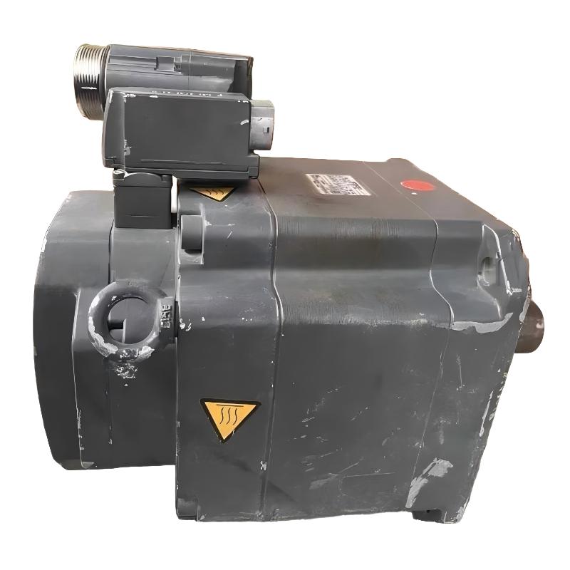
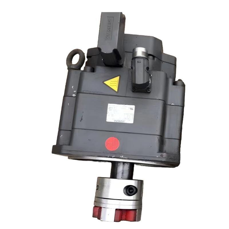
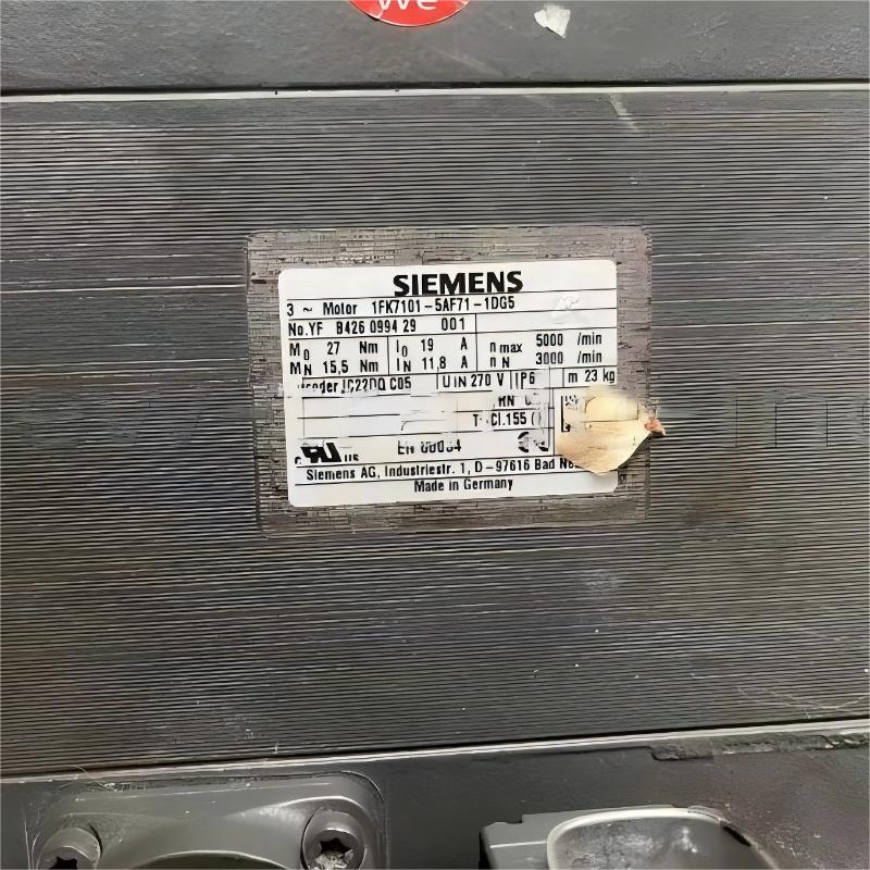
- Siemens
- 1FK7101-5AF71-1DG5
- SIMOTICS S Synchronous Motor
- Germany
- 300 mm x 200 mm x 150 mm
- 23kg
- Xiamen, China
- New & In Stock
- T/T, PayPal, Western Union
- 1 Year
- 1-3 Working Days
- DHL, UPS, TNT, FedEx and EMS.
- 24-Hour Service
- COO
- 7
Our advantage

Global Logistics
We have a 10-year logistics and express cooperation agreement, so our products can be shipped to any place in the world.

Brand new and original
Our products are imported in bulk from the place of origin. Because of the cooperative relationship, our products are all original and 100% new.

24-hour service
We provide 7*24 hours service to our customers. We will be there whenever you need us.

Price advantage
All our products are priced very favorably because we have our own warehouse and supply.
| Company Information | |||
| [email protected] | |||
| Mobile | +8615980777398 | ||
| +8615980777398 | |||
| 15980777398 |
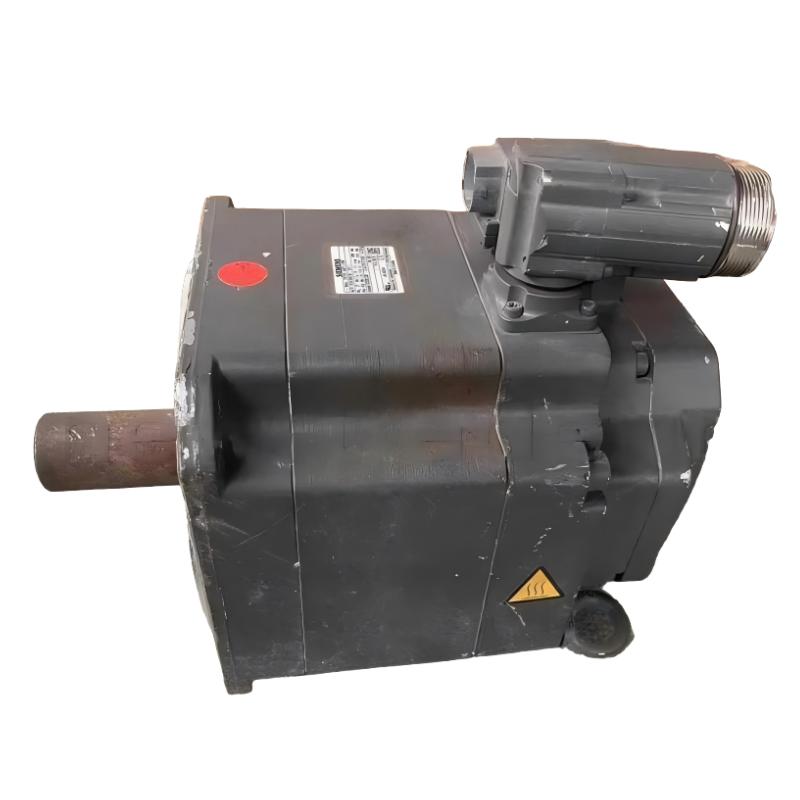
Siemens 1FK7101-5AF71-1DG5 Servo Motor: Product Specifications, Technical Overview, Applications, Advantages, and Related Models
1. Product Overview
The Siemens 1FK7101-5AF71-1DG5 is a model designation from the SIMOTICS family of industrial servo motors. Motors in this product family are designed for applications that require controlled rotational movement, accurate positioning, repeatable motion, and reliable integration with industrial automation systems.
Servo motors are widely used in automated production lines, CNC machinery, packaging equipment, material-handling systems, assembly machines, and other applications in which the position, speed, and torque of a mechanical axis must be controlled accurately.
The 1FK series is associated with permanent-magnet synchronous servo motor technology. Depending on the exact motor configuration, a drive system can combine the motor with an appropriate servo drive, feedback device, mechanical coupling, and motion controller to achieve coordinated and repeatable movement.
The complete model number, 1FK7101-5AF71-1DG5, identifies a specific motor configuration rather than simply a general motor type. The characters within the designation can distinguish product family, frame or size category, winding configuration, feedback arrangement, mechanical features, and other ordering characteristics.
Because the exact configuration is important when selecting a replacement motor, the full designation should be retained when preparing a quotation, purchasing a spare part, planning a retrofit, or checking mechanical compatibility.
The following sections provide a detailed product description, a practical explanation of the motor’s applications and advantages, and comparison tables for related models.
Technical accuracy note: The exact rated power, rated torque, rated speed, shaft dimensions, overall dimensions, and net weight of the complete 1FK7101-5AF71-1DG5 configuration cannot be established reliably from the model designation alone. These values should not be treated as confirmed specifications without the corresponding motor nameplate or technical datasheet. Where exact values are unavailable, this guide identifies the relevant parameters and distinguishes verified product-family characteristics from configuration-dependent information.
2. Basic Product Information
The following table summarizes the principal identification and selection characteristics of the 1FK7101-5AF71-1DG5 servo motor.
| Parameter | Product Information |
|---|---|
| Model | 1FK7101-5AF71-1DG5 |
| Brand | Siemens |
| Product Family | SIMOTICS |
| Product Series | 1FK servo motor series; exact subseries configuration requires confirmation |
| Product Category | Industrial servo motor |
| Motor Technology | Permanent-magnet synchronous servo motor technology, subject to confirmation for the exact order code |
| Primary Function | Controlled rotational motion |
| Typical Control Method | Closed-loop servo control when paired with a suitable feedback and drive system |
| Main Application Areas | Industrial automation, precision machinery, CNC equipment, packaging machinery, and automated production systems |
| Drive Compatibility | Requires a compatible servo drive selected according to the motor’s electrical and feedback specifications |
| Feedback System | Configuration-dependent; exact encoder or resolver type requires confirmation |
| Mounting Arrangement | Must be confirmed from the exact mechanical configuration |
| Shaft Configuration | Requires confirmation from the dimensional drawing |
| Rated Power | To be confirmed from the exact motor datasheet |
| Rated Torque | To be confirmed from the exact motor datasheet |
| Rated Speed | To be confirmed from the exact motor datasheet |
| Maximum Speed | To be confirmed from the exact motor datasheet |
| Rated Voltage | To be confirmed from the motor nameplate |
| Rated Current | To be confirmed from the motor nameplate |
| Protection Rating | To be confirmed for the exact configuration |
| Overall Dimensions | To be confirmed from the dimensional drawing |
| Shaft Dimensions | To be confirmed from the dimensional drawing |
| Net Weight (kg) | To be confirmed from the product datasheet or physical measurement |
| Cooling Method | To be confirmed for the exact motor configuration |
| Installation Environment | Must comply with the motor’s specified temperature, humidity, vibration, and protection requirements |
| Recommended Use | Applications requiring controlled movement, positioning, speed regulation, and repeatability |
The table identifies the information needed for technical evaluation and procurement. The exact electrical and mechanical specifications must be established before the motor is integrated into an existing machine.
3. Detailed Product Description
3.1 General Description
The Siemens 1FK7101-5AF71-1DG5 is identified as a specific model within the 1FK servo motor designation family.
Industrial servo motors are designed to convert electrical energy into controlled mechanical movement. Unlike a conventional motor operating primarily at a fixed or broadly regulated speed, a servo motor is normally used as part of a coordinated control system that regulates position, speed, and torque according to the machine’s operating requirements.
In a typical servo application, the motor receives commands from a servo drive. The drive regulates the electrical power supplied to the motor and uses feedback information, where provided, to control the motor’s movement.
This arrangement allows a machine to perform repeated positioning operations, follow programmed motion profiles, accelerate and decelerate in a controlled manner, and coordinate several axes during an automated process.
The specific performance of the 1FK7101-5AF71-1DG5 depends on its electrical configuration, feedback equipment, drive compatibility, mechanical design, and operating conditions.
For this reason, the complete model designation is important when determining whether the motor is suitable for a particular machine.
3.2 Product Design and Operating Principle
Permanent-magnet synchronous servo motors generally use permanent magnets in the rotor and electrically energized windings in the stator.
When the motor is supplied with appropriately controlled electrical power, the interaction between the magnetic field of the rotor and the electromagnetic field generated by the stator produces rotational torque.
The servo drive controls the motor’s electrical operation to produce the requested movement.
Depending on the control architecture, the system can regulate several operating variables.
Position control: The system moves the motor to a target position and maintains the commanded position within the limits of the control system and mechanical assembly.
Speed control: The system regulates the rotational speed of the motor according to the machine’s operating requirements.
Torque control: The system regulates motor torque within the available electrical, thermal, and mechanical limits.
Acceleration and deceleration control: The drive can follow programmed acceleration and deceleration profiles to reduce unnecessary mechanical shock and improve motion consistency.
Coordinated motion: Multiple servo axes can be synchronized to support complex production sequences, interpolation, electronic gearing, and other motion-control functions when the complete control system supports them.
These functions are characteristics of appropriately configured servo systems. Their availability and achievable performance depend on the exact motor, drive, feedback device, controller, and application.
3.3 Industrial Construction
Industrial servo motors are generally designed for repeated operation in machinery environments where mounting accuracy, mechanical stability, thermal management, and electrical compatibility are important.
Important construction considerations include the motor housing, stator and rotor assembly, bearings, shaft, feedback components, electrical connections, and mounting interfaces.
The shaft transfers motor torque to the driven mechanism. Depending on the machine, the shaft may connect directly to a mechanical load or operate through a coupling, gearbox, belt transmission, or other power-transmission component.
Bearing selection and shaft alignment are important because excessive radial or axial loading can shorten service life and affect positioning performance.
The motor’s mounting flange and shaft dimensions must also match the machine’s mechanical design. Even when two motors belong to the same general product family, differences in mounting arrangement, shaft geometry, connector orientation, or feedback configuration can prevent direct interchangeability.
The exact construction details of the 1FK7101-5AF71-1DG5 should therefore be checked against its dimensional drawing and ordering data.
4. Product Parameters and Technical Specifications
The following table separates essential technical parameters from values that require confirmation for the exact model.
4.1 Electrical and Mechanical Parameters
| Parameter | Specification | Technical Significance |
|---|---|---|
| Model | 1FK7101-5AF71-1DG5 | Identifies the specific ordering configuration |
| Brand | Siemens | Manufacturer identification |
| Product Family | SIMOTICS | Industrial motor product family |
| Series | 1FK | Servo motor designation family |
| Motor Type | Permanent-magnet synchronous servo motor technology associated with the family; exact configuration to be confirmed | Determines operating principle and drive requirements |
| Rated Power | Not confirmed | Used to assess continuous power requirements |
| Rated Torque | Not confirmed | Determines the motor’s continuous torque capability |
| Maximum Torque | Not confirmed | Important for acceleration and short-duration load requirements |
| Rated Speed | Not confirmed | Indicates the specified operating speed under rated conditions |
| Maximum Speed | Not confirmed | Defines the upper permitted operating speed |
| Rated Voltage | Not confirmed | Required for drive and electrical-system selection |
| Rated Current | Not confirmed | Used for electrical sizing and drive compatibility |
| Peak Current | Not confirmed | Important for short-duration torque demands |
| Number of Pole Pairs | Not confirmed | Relevant to electrical frequency and motor-control calculations |
| Rotor Inertia | Not confirmed | Influences acceleration, deceleration, and motion-system tuning |
| Winding Configuration | Ordering-code dependent | Affects electrical performance and compatibility |
| Feedback Device | Not confirmed | Determines the available position or speed feedback |
| Encoder Resolution | Not confirmed | Important for feedback granularity and control-system configuration |
| Brake | Not confirmed | Determines whether a holding brake is available |
| Brake Holding Torque | Not confirmed | Relevant if a brake-equipped configuration is installed |
| Cooling Method | Not confirmed | Influences thermal performance and installation requirements |
| Insulation Characteristics | Refer to the exact motor documentation | Relevant to electrical safety and operating limits |
| Protection Rating | Not confirmed | Determines protection against dust and water ingress |
| Operating Temperature | Refer to the exact motor documentation | Defines the permitted ambient operating range |
| Installation Altitude | Refer to the exact motor documentation | May affect thermal performance and permitted loading |
| Overall Dimensions | Not confirmed | Required for machine layout and installation |
| Mounting Dimensions | Not confirmed | Required to match the machine interface |
| Shaft Diameter | Not confirmed | Determines coupling and transmission compatibility |
| Shaft Length | Not confirmed | Determines mechanical engagement and assembly clearance |
| Shaft-End Design | Not confirmed | Relevant to couplings, keyways, and other interfaces |
| Net Weight (kg) | Not confirmed | Required for transport, handling, and structural calculations |
| Cable and Connector Type | Not confirmed | Determines wiring and installation compatibility |
| Recommended Drive | Must be selected from the exact motor and feedback specifications | Ensures electrical and control compatibility |
| Control Method | Depends on the selected drive and controller | Determines available motion-control functions |
4.2 Dimensions and Weight
Dimensions and weight are particularly important when replacing an existing motor or designing a new machine.
The following dimensional information should be obtained before installation.
| Dimensional Parameter | Required Value | Purpose |
|---|---|---|
| Model | 1FK7101-5AF71-1DG5 | Confirms the exact motor configuration |
| Frame or Housing Size | To be confirmed | Establishes the motor’s general mounting envelope |
| Overall Length | To be confirmed in mm | Determines the required installation space |
| Overall Height | To be confirmed in mm | Determines vertical clearance |
| Overall Width or Housing Diameter | To be confirmed in mm | Determines lateral clearance |
| Flange Dimensions | To be confirmed in mm | Ensures compatibility with the mounting surface |
| Flange Bolt-Circle Dimensions | To be confirmed in mm | Establishes mounting-hole positions |
| Mounting-Hole Diameter | To be confirmed in mm | Determines fastener compatibility |
| Shaft Diameter | To be confirmed in mm | Ensures coupling compatibility |
| Shaft Length | To be confirmed in mm | Determines the available coupling engagement |
| Shaft-End Dimensions | To be confirmed in mm | Supports accurate mechanical design |
| Connector Clearance | To be confirmed | Prevents interference with cables and adjacent components |
| Rear Clearance | To be confirmed | Provides space for connectors and service access |
| Net Weight (kg) | To be confirmed | Supports lifting, shipping, and mounting calculations |
| Shipping Weight (kg) | To be confirmed separately | Includes packaging and potentially other supplied components |
Important: Overall length, shaft dimensions, and weight should not be estimated from the model name. Incorrect dimensional information can result in an unsuitable replacement, mounting problems, unexpected coupling loads, or delays during machine installation.
For a replacement project, the preferred method is to compare the complete ordering designation, nameplate data, mounting drawing, shaft drawing, and feedback connections of the original motor with those of the proposed replacement.
5. Product Applications
The following applications describe common uses for industrial servo motors. They are potential application areas rather than confirmation that every application is suitable for the exact 1FK7101-5AF71-1DG5 configuration.
5.1 CNC Machine Tools
CNC machinery uses controlled motor movement to position tools, workpieces, and mechanical axes according to programmed instructions.
Servo motors may be used for feed axes, auxiliary movements, tool-handling mechanisms, and other controlled motions.
Typical requirements include:
- Accurate positioning.
- Repeatable movement.
- Controlled acceleration and deceleration.
- Stable operation under changing mechanical loads.
- Coordination between multiple axes.
- Reliable integration with the machine’s motion controller.
For a CNC application, motor selection must consider the required axis torque, speed range, reflected load inertia, acceleration profile, duty cycle, and feedback resolution.
The motor’s mechanical interface must also match the ballscrew, gearbox, coupling, or other transmission system.
5.2 Packaging Machinery
Automated packaging equipment often requires coordinated movement between feeding, sealing, cutting, labeling, and product-transfer mechanisms.
Servo motors can provide controlled motion for these processes.
Potential applications include:
- Film feeding.
- Label positioning.
- Cutting mechanisms.
- Product indexing.
- Carton handling.
- Packaging-material tension control.
- Synchronization between conveyor and packaging axes.
In packaging equipment, repeatability and cycle-time consistency are often more important than maximum motor speed alone.
A correctly selected servo system can help reduce positioning errors and improve coordination between different machine operations.
5.3 Automated Assembly Equipment
Assembly machines frequently use servo motors to move components into defined positions before fastening, inserting, pressing, or joining operations.
Examples include electronic component assembly, mechanical component installation, and automated fixture positioning.
The principal benefits of servo control in these applications are accurate positioning, programmable movement profiles, and the ability to coordinate multiple mechanical axes.
However, applications involving pressing or insertion forces may require additional force measurement, torque monitoring, or specialized motion-control functions.
Motor torque capacity alone does not establish the force that can safely be applied to a workpiece. The transmission ratio, mechanical geometry, control strategy, and structural limits must also be considered.
5.4 Material Handling and Transfer Systems
Servo motors can control positioning and movement in automated material-handling equipment.
Potential uses include transfer mechanisms, indexing tables, pick-and-place systems, and controlled conveyor sections.
The required motor characteristics depend on the payload, travel distance, acceleration, transmission arrangement, and required positioning accuracy.
For vertical axes, engineers must also evaluate gravitational loading and the consequences of power loss.
Where a vertical axis requires a holding brake, the selected motor must have the appropriate brake configuration and holding capacity. The presence of a brake must be confirmed for the exact motor rather than assumed.
5.5 Robotic and Multi-Axis Machinery
Industrial automation systems often coordinate several motorized axes to produce a programmed movement.
Servo motors can support applications that require synchronized motion, repeatable trajectories, and controlled changes in speed.
Examples include automated positioning units, handling mechanisms, special-purpose machines, and certain robotic subsystems.
The motor must be evaluated against the axis’s torque demand, speed range, inertia, duty cycle, and control requirements.
For robotic applications, the motor’s dimensions and mass may also influence the design of moving components.
The suitability of the 1FK7101-5AF71-1DG5 for a specific robotic axis cannot be determined without its exact specifications and the mechanical requirements of that axis.
5.6 Printing and Converting Machinery
Printing, laminating, cutting, winding, and converting machines often require controlled movement across multiple processing stages.
Servo systems may be used to coordinate feed rollers, cutting tools, registration mechanisms, and indexing devices.
Important requirements include repeatable positioning, synchronization, controlled acceleration, and stable operation over repeated production cycles.
The exact selection depends on whether the motor drives a high-inertia roller, a lightweight positioning axis, a tension-control mechanism, or another type of load.
5.7 General Industrial Automation
Servo motors can also be used in specialized production equipment that requires programmable motion.
Examples include automated inspection fixtures, indexing stations, machine-tool accessories, and customized manufacturing equipment.
In each case, the motor should be selected according to the actual motion profile rather than by comparing model numbers alone.
6. Product Advantages
The following advantages describe the benefits generally associated with a correctly configured industrial servo motor and drive system. Actual performance depends on the specific motor configuration, drive, mechanical load, and operating conditions.
6.1 Precise Motion Control
A servo system can regulate motor movement according to programmed position, speed, or torque commands.
This is valuable when a machine must repeatedly move a component to a specified location or maintain a defined relationship between multiple mechanical axes.
Precise control can improve production consistency and reduce positioning errors when the complete system is correctly designed and tuned.
6.2 Repeatable Positioning
Repeatability is essential in automated production.
A properly configured servo system can return a mechanism to the same commanded position repeatedly, subject to the limitations of the motor, feedback device, mechanical transmission, and control system.
This can be useful in assembly, packaging, cutting, indexing, and other processes in which consistent movement is required.
It is important to distinguish feedback resolution from actual positioning accuracy. Mechanical backlash, compliance, thermal expansion, mounting errors, and load variation can affect the final position.
6.3 Controlled Acceleration and Deceleration
Servo drives can regulate acceleration and deceleration according to programmed motion profiles.
This allows engineers to adjust movement to suit the machine’s cycle time and mechanical limitations.
Controlled motion can help reduce unnecessary mechanical shock, vibration, and abrupt changes in load.
The appropriate profile depends on the driven mechanism, available torque, inertia, and required operating speed.
6.4 Integration with Automation Systems
A servo motor can be integrated into a larger automation system through a compatible drive and controller.
Depending on the selected equipment, the system may support coordinated axes, programmed motion sequences, diagnostic functions, and communication with a higher-level machine controller.
The exact communication protocols and available control functions must be verified for the selected drive and control architecture.
6.5 Support for Repetitive Production
Many industrial machines perform the same movement thousands or millions of times over their operating life.
A correctly sized servo motor can support repeated motion cycles within its permitted thermal, electrical, and mechanical limits.
Appropriate sizing is important because an undersized motor may overheat or fail to achieve the required acceleration, while an unnecessarily oversized motor may increase system cost and complicate optimization.
6.6 Flexible Motion Profiles
Servo systems can often be programmed to perform different movement profiles without changing the basic mechanical system.
This can be useful when a machine produces different product sizes, operates at multiple speeds, or uses several manufacturing recipes.
The flexibility depends on the controller, drive functions, software, and machine design.
6.7 Potential for Reduced Mechanical Wear
Controlled acceleration, deceleration, and torque can reduce unnecessary mechanical shock compared with poorly controlled motion.
However, a servo motor does not automatically eliminate wear.
Bearing life, shaft loading, coupling alignment, lubrication, transmission design, contamination, and operating temperature remain important factors in long-term reliability.
6.8 Suitability for Integrated Machine Design
A servo motor can form part of a compact drive assembly when its dimensions, mounting arrangement, connectors, and mechanical interfaces match the machine.
This can simplify the design of positioning units and automated mechanisms.
For the 1FK7101-5AF71-1DG5, the actual installation space and mechanical compatibility must be established from the exact dimensional documentation.
7. Brand and Product Series
7.1 Brand: Siemens
The brand associated with the product designation is Siemens.
The product should be identified using its full model number when requesting quotations, checking inventory, ordering spare parts, or confirming compatibility.
The full designation is more useful than the brand and series name alone because products in the same family may have different electrical and mechanical configurations.
7.2 Product Family: SIMOTICS
SIMOTICS is a motor product-family name associated with Siemens industrial motor products.
The family encompasses motor technologies intended for different industrial applications. The SIMOTICS designation alone does not establish the rated power, dimensions, weight, feedback type, or drive compatibility of a specific motor.
7.3 Product Series: 1FK
The 1FK designation identifies a servo motor product family.
Motors carrying a related 1FK designation may differ in frame size, winding, rated torque, speed, feedback configuration, mechanical construction, and other ordering characteristics.
Consequently, a related 1FK model should not automatically be regarded as a direct substitute for the 1FK7101-5AF71-1DG5.
7.4 Product Positioning
The general purpose of an industrial servo motor is to provide controlled mechanical movement within an automated system.
The exact application suitability of the 1FK7101-5AF71-1DG5 depends on its rated operating characteristics and the requirements of the machine.
Before purchasing, the following items should be checked:
- Complete motor designation.
- Rated power and rated torque.
- Rated and maximum speed.
- Rated current and voltage.
- Feedback device and electrical interface.
- Shaft and mounting dimensions.
- Overall dimensions and net weight.
- Brake configuration, if required.
- Compatible drive and controller.
- Environmental and installation requirements.
8. Five Related Models for Comparison
The following table presents five candidate model designations for further investigation within the broader 1FK servo motor family.
Important selection limitation: The models below are comparison candidates, not confirmed drop-in replacements. Their exact order codes, availability, dimensions, weights, and technical specifications must be checked before procurement. The numerical specifications have deliberately not been invented.
| No. | Model | Product Family | Motor Category | Rated Power | Rated Torque | Rated Speed | Dimensions (mm) | Net Weight (kg) | Selection Considerations |
|---|---|---|---|---|---|---|---|---|---|
| 1 | 1FK7101-5AF71-1DG5 | SIMOTICS 1FK | Servo motor | To be confirmed | To be confirmed | To be confirmed | To be confirmed | To be confirmed | Reference model; establish exact original specifications |
| 2 | 1FK7101-5AF71-1DA5 | 1FK designation family | Servo motor candidate | To be confirmed | To be confirmed | To be confirmed | To be confirmed | To be confirmed | Confirm that this complete ordering designation exists and establish its configuration before comparison |
| 3 | 1FK7101-5AF71-1EA5 | 1FK designation family | Servo motor candidate | To be confirmed | To be confirmed | To be confirmed | To be confirmed | To be confirmed | Requires confirmation of the complete model designation and ordering characteristics |
| 4 | 1FK7101-5AF71-1AG5 | 1FK designation family | Servo motor candidate | To be confirmed | To be confirmed | To be confirmed | To be confirmed | To be confirmed | Do not assume equivalence; confirm the exact ordering code and mechanical interfaces |
| 5 | 1FK7101-5AF71-1EG5 | 1FK designation family | Servo motor candidate | To be confirmed | To be confirmed | To be confirmed | To be confirmed | To be confirmed | Verify model existence, electrical characteristics, feedback, and dimensions before selection |
| 6 | 1FK7101-5AF71-1DG5 | SIMOTICS 1FK | Servo motor | To be confirmed | To be confirmed | To be confirmed | To be confirmed | To be confirmed | Reference configuration for a side-by-side technical comparison |
Model-number caution: The five alternative suffix combinations in this table are unverified candidate strings, not confirmed commercially available products. They should not be used as purchase orders or replacement recommendations without checking the complete model number against an authoritative product record.
For a technically reliable shortlist, it is preferable to obtain five confirmed order numbers that match the original motor’s frame, rated torque, speed, feedback, mounting, and shaft requirements.
8.1 How to Evaluate the Related Models
When comparing motors within the same product family, the following criteria should be evaluated in order of importance.
First, establish the mechanical fit. Compare flange dimensions, shaft diameter, shaft length, mounting-hole arrangement, total length, and connector clearance. Mechanical compatibility is necessary before electrical equivalence can be considered.
Second, compare torque and speed. The replacement must meet the machine’s continuous torque requirements and its peak torque requirements during acceleration or other demanding operating conditions.
Third, compare electrical characteristics. Rated voltage, current, winding configuration, and the permitted operating range must match the selected drive.
Fourth, verify the feedback system. The feedback device and its interface must be supported by the drive and controller. Similar-looking motors may have different feedback arrangements.
Fifth, verify dimensions and weight. The replacement must fit the installation space, and its mass must be suitable for the mechanical structure.
Finally, check operating conditions. Duty cycle, temperature, vibration, contamination, braking requirements, and installation orientation can affect suitability.
A model that shares the same general series designation may still be unsuitable if any of these characteristics differ significantly.
9. Five Siemens Motor Models for a Broader Comparison
The following table provides five additional model designations to investigate when comparing industrial servo motors and motion-control solutions.
These entries are intended as a preliminary selection framework. The exact ordering codes and technical data must be confirmed before treating them as available products or suitable alternatives.
| No. | Model | Brand | Product Family | Product Type | Rated Power | Rated Torque | Rated Speed | Dimensions (mm) | Net Weight (kg) |
|---|---|---|---|---|---|---|---|---|---|
| 1 | 1FK7042-5AF71-1DG5 | Siemens | SIMOTICS 1FK | Servo motor candidate | To be confirmed | To be confirmed | To be confirmed | To be confirmed | To be confirmed |
| 2 | 1FK7063-5AF71-1DG5 | Siemens | SIMOTICS 1FK | Servo motor candidate | To be confirmed | To be confirmed | To be confirmed | To be confirmed | To be confirmed |
| 3 | 1FK7083-5AF71-1DG5 | Siemens | SIMOTICS 1FK | Servo motor candidate | To be confirmed | To be confirmed | To be confirmed | To be confirmed | To be confirmed |
| 4 | 1FK7101-5AF71-1DG5 | Siemens | SIMOTICS 1FK | Reference servo motor | To be confirmed | To be confirmed | To be confirmed | To be confirmed | To be confirmed |
| 5 | 1FK7105-5AF71-1DG5 | Siemens | SIMOTICS 1FK | Servo motor candidate | To be confirmed | To be confirmed | To be confirmed | To be confirmed | To be confirmed |
Important: The model strings in this comparison have not been verified as complete, valid order numbers. In particular, similar-looking model designations do not establish that the same suffix combination is available across different frame sizes. Confirm each full designation before using the table for purchasing.
The table also does not establish that these are the five most popular Siemens motor models. Popularity depends on the market, application, installed equipment base, and availability of the specific configuration.
9.1 How to Choose Among the Broader Model Candidates
A smaller or larger model designation should not be used as the sole basis for selecting a replacement.
The correct selection should be based on the machine’s actual requirements.
| Selection Criterion | Information Required | Why It Matters |
|---|---|---|
| Model | Full manufacturer ordering code | Prevents confusion between configurations |
| Required Power | Continuous mechanical power demand | Ensures adequate operating capacity |
| Required Torque | Continuous and peak torque | Determines whether the motor can accelerate and drive the load |
| Operating Speed | Continuous and maximum speed requirements | Ensures the required production rate can be achieved |
| Load Inertia | Reflected inertia and motor rotor inertia | Influences acceleration and servo tuning |
| Mounting Dimensions | Flange and bolt-hole measurements | Determines mechanical compatibility |
| Shaft Dimensions | Diameter, length, and shaft-end geometry | Determines coupling compatibility |
| Overall Dimensions | Length, width or diameter, and connector clearance | Determines whether the motor fits the machine |
| Net Weight (kg) | Actual motor mass | Affects handling and moving-axis loads |
| Feedback | Encoder or other feedback specification | Determines compatibility with the drive |
| Brake | Required holding function and brake rating | Important for vertical or gravity-loaded axes |
| Drive Compatibility | Supported motor and feedback combination | Ensures the complete servo system can operate correctly |
| Environment | Temperature, contamination, vibration, and mounting conditions | Influences service life and reliability |
| Availability | Confirmed ordering status and delivery terms | Determines procurement feasibility |
10. Installation and Integration Considerations
Correct installation is essential to obtaining the intended performance from an industrial servo motor.
Even a motor with suitable rated torque and speed can experience poor performance if the mechanical assembly, drive configuration, or feedback wiring is incorrect.
10.1 Mechanical Installation
The motor mounting surface should be suitable for the motor’s mechanical loads and installation arrangement.
Mounting bolts must match the specified dimensions and tightening requirements.
The coupling or transmission system should be aligned correctly to prevent excessive shaft loading.
If a gearbox, belt drive, or ballscrew is used, the resulting radial and axial loads must remain within the motor’s permitted limits.
Before installation, verify the following:
- Flange dimensions.
- Mounting-hole positions.
- Shaft diameter and length.
- Coupling dimensions.
- Total motor length.
- Cable and connector clearance.
- Motor weight and mounting support.
- Permitted radial and axial shaft loads.
10.2 Electrical Installation
The servo drive must support the motor’s electrical characteristics.
The wiring arrangement should follow the specified connection diagram, and protective grounding must be implemented correctly.
Motor power cables and feedback cables should be installed according to the system’s electrical and electromagnetic compatibility requirements.
Incorrect wiring can cause faults, unreliable feedback, excessive electrical noise, or equipment damage.
10.3 Drive Configuration
The servo drive must be configured for the correct motor and feedback system.
Important parameters can include motor identification, feedback type, current limits, speed limits, control-loop settings, braking behavior, and motion limits.
The drive should not be configured using assumed values from a similar motor.
Where supported, the manufacturer’s motor identification and commissioning functions should be used according to the relevant equipment documentation.
10.4 Commissioning
Commissioning should begin with the machine in a safe state.
A suitable procedure includes:
- Confirm the complete motor and drive designations.
- Inspect the mechanical installation.
- Check protective grounding and electrical connections.
- Confirm that the feedback device is recognized correctly.
- Verify motor and drive parameters.
- Test movement at a low speed where appropriate.
- Check the direction of rotation.
- Verify the commanded position and actual feedback.
- Evaluate acceleration and deceleration.
- Check for abnormal noise, vibration, heating, or unexpected motion.
The machine should only be operated within the specified electrical, mechanical, and thermal limits.
11. Maintenance and Troubleshooting
Routine inspection helps identify developing problems before they cause an unexpected production interruption.
The maintenance requirements depend on the motor configuration, machine environment, operating hours, load profile, and manufacturer’s instructions.
11.1 Routine Inspection
Maintenance personnel should check the motor and its installation for visible damage, unusual noise, vibration, loose mounting hardware, cable deterioration, and signs of overheating.
Connectors should remain properly secured, and the mounting structure should remain stable.
Any maintenance involving electrical connections should be carried out under the applicable isolation and safety procedures.
11.2 Common Symptoms and Possible Causes
| Symptom | Possible Causes | Recommended Checks |
|---|---|---|
| Motor does not start | Drive disabled, incorrect wiring, active fault, or incompatible configuration | Check drive status, fault messages, and wiring |
| Positioning error | Incorrect feedback configuration, mechanical backlash, tuning problems, or excessive load | Check feedback, coupling, transmission, and control parameters |
| Excessive heating | Overload, insufficient cooling, incorrect settings, or unsuitable duty cycle | Check load, current, cooling, and operating profile |
| Abnormal vibration | Mechanical misalignment, resonance, bearing problems, or poor tuning | Inspect mechanical assembly and servo settings |
| Unexpected stopping | Drive protection, overload, communication interruption, or feedback fault | Review fault history and operating conditions |
| Inconsistent speed | Changing load, incorrect tuning, feedback problems, or unsuitable control settings | Check load conditions, feedback, and control-loop configuration |
| Excessive mechanical noise | Misalignment, damaged bearings, transmission problems, or loose mounting | Inspect the motor and connected machinery |
| Drive reports a feedback fault | Incorrect feedback wiring, incompatible feedback interface, or damaged components | Verify the exact motor and drive combination |
These are general troubleshooting possibilities rather than diagnoses of a known fault in the 1FK7101-5AF71-1DG5.
12. Purchasing and Replacement Recommendations
When purchasing this motor, the most important requirement is to confirm that the supplied product matches the intended application.
The complete ordering code should be included in the purchase request.
If the motor is intended to replace an existing unit, the original motor’s nameplate information should be recorded before an alternative is selected.
12.1 Information to Request from the Supplier
| Item | Required Information |
|---|---|
| Model | 1FK7101-5AF71-1DG5 |
| Brand | Siemens |
| Product Family | SIMOTICS |
| Product Series | 1FK |
| Product Status | Confirm the applicable ordering and supply status |
| Rated Power | Exact value and unit |
| Rated Torque | Exact value in Nm |
| Maximum Torque | Exact value in Nm |
| Rated Speed | Exact value in rpm |
| Maximum Speed | Exact value in rpm |
| Rated Voltage | Exact value and unit |
| Rated Current | Exact value and unit |
| Feedback Device | Exact type and interface |
| Brake | Confirm whether fitted and provide the relevant rating |
| Overall Dimensions | Length, width or diameter, and height in mm |
| Mounting Dimensions | Flange dimensions and mounting-hole measurements in mm |
| Shaft Dimensions | Diameter and length in mm |
| Net Weight (kg) | Exact motor weight excluding packaging |
| Shipping Weight (kg) | Packed shipment weight |
| Accessories | Confirm which connectors, cables, or other components are included |
| Documentation | Dimensional drawing and technical data |
| Condition | New, unused stock, refurbished, or used |
| Warranty | Applicable warranty terms |
| Compatibility | Confirmation of the intended drive and feedback configuration |
12.2 New Motor or Replacement Motor?
The correct purchasing choice depends on the condition of the existing equipment and the machine’s operational requirements.
A new motor may be preferable when long-term availability, warranty coverage, and predictable service history are important.
A replacement motor from existing inventory may be appropriate when its exact configuration and condition can be verified.
A refurbished motor may be considered when cost or availability is a concern, but its condition, repair history, testing procedure, and warranty should be evaluated carefully.
Regardless of the purchase route, a lower price should not take precedence over correct electrical and mechanical compatibility.
13. Summary of the 1FK7101-5AF71-1DG5
The Siemens 1FK7101-5AF71-1DG5 is identified as a model within the 1FK servo motor designation family associated with SIMOTICS.
Its intended role is consistent with the general purpose of industrial servo motors: providing controlled rotational movement as part of an automated machine or motion-control system.
Potential application areas include CNC machinery, packaging equipment, automated assembly, material handling, and other industrial applications that require repeatable motion.
The principal benefits of a correctly configured servo system include controlled positioning, programmable acceleration and deceleration, coordinated motion, and repeatable operation.
However, the suitability of this specific model cannot be established from its designation alone.
The most important missing information is its exact electrical configuration, rated performance, feedback arrangement, mechanical dimensions, and net weight.
The related-model tables above provide a preliminary comparison framework, but the alternative ordering codes have not been verified. They should not be treated as confirmed products or direct replacements without further technical validation.
For engineering and purchasing purposes, the most reliable approach is to confirm the complete ordering code and obtain the corresponding technical data before making a final selection.
Final recommendation: If the purpose is to replace an existing 1FK7101-5AF71-1DG5 motor, prioritize an exact configuration match. If the purpose is to select a new motor for a machine, determine the required torque, speed, power, feedback, mounting dimensions, and weight before comparing alternatives.
This approach reduces the risk of ordering an incompatible motor and provides a sound basis for technical evaluation, procurement, installation, and long-term maintenance.