

ProductPRODUCT
Featured products
Contact Us
- Schneider
- METSEPM5310
- Power Meter
- France
- 96 x 72 x 96 mm
- 0.43 kg
- Xiamen, China
- New & In Stock
- T/T, PayPal, Western Union
- 1 Year
- 1-3 Working Days
- DHL, UPS, TNT, FedEx and EMS.
- 24-Hour Service
- COO
- 6
Our advantage

Global Logistics
We have a 10-year logistics and express cooperation agreement, so our products can be shipped to any place in the world.

Brand new and original
Our products are imported in bulk from the place of origin. Because of the cooperative relationship, our products are all original and 100% new.

24-hour service
We provide 7*24 hours service to our customers. We will be there whenever you need us.

Price advantage
All our products are priced very favorably because we have our own warehouse and supply.
| Company Information | |||
| [email protected] | |||
| Mobile | +8615980777398 | ||
| +8615980777398 | |||
| 15980777398 |
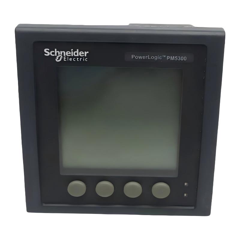
Product Overview
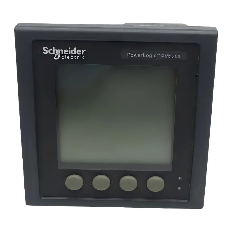
The Schneider Electric METSEPM5310 PowerLogic PM5310 Power Meter is a multifunction electrical measurement instrument designed for monitoring power consumption and electrical operating conditions in low-voltage distribution systems. As part of the PowerLogic PM5000 series, it provides measurements that help facility operators, electrical engineers, and industrial maintenance teams understand energy consumption, assess electrical loading, and improve power management.
The METSEPM5310 measures electrical parameters including voltage, current, frequency, power factor, active power, reactive power, and energy. It also supports power quality analysis up to the 31st harmonic, helping users investigate certain types of electrical distortion and identify conditions that may require further assessment.
The meter features a backlit LCD display and supports panel mounting. Its communication capabilities include Modbus RTU and ASCII over a two-wire RS-485 connection, allowing measured values to be integrated into compatible supervisory control systems, building management platforms, and energy monitoring applications.
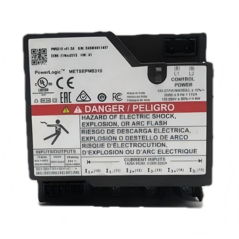
The device supports several electrical network configurations, including single-phase with neutral, three-phase, and three-phase with neutral. Its current measurement inputs are designed for 1 A or 5 A current-transformer secondary circuits, depending on the installation and selected configuration.
The METSEPM5310 also provides two digital inputs, two digital outputs, configurable alarms, and data recording functions. These capabilities make it useful for applications that require more than a basic voltage or current display, particularly where electrical measurements need to be collected centrally for analysis and reporting.
For industrial automation systems, the meter can serve as an electrical monitoring point alongside PLCs, supervisory systems, and power distribution equipment. It measures and communicates electrical information rather than directly controlling motor speed or replacing protective relays.
Technical Specifications
| Parameter | Specification |
|---|---|
| Brand | Schneider Electric |
| Product Series | PowerLogic PM5000 |
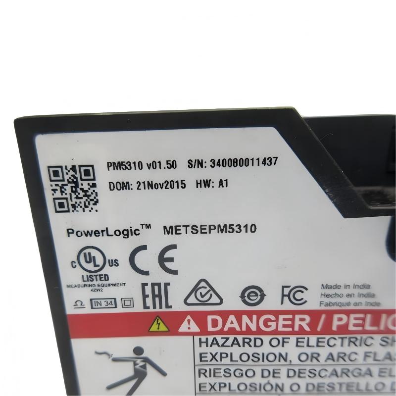
| Model | METSEPM5310 |
| Device Name | PM5310 Power Meter |
| Product Type | Multifunction Power Meter |
| Primary Application | Electrical power and energy monitoring |
| Display | Backlit LCD |
| Display Resolution | 128 × 128 pixels |
| Mounting Type | Flush / panel mounted |
| Rated Supply Voltage | 100–415 V AC or 125–250 V DC, according to the applicable datasheet revision |
| Supply Frequency | 45–65 Hz for AC supply |
| Rated Current Input | 1 A or 5 A |
| Supported Network Types | 1P + N, 3P, 3P + N |
| Phase-to-Phase Measurement Range | Up to 690 V AC in the applicable specification |
| Phase-to-Neutral Measurement Range | Up to 400 V AC in the applicable specification |
| Measurement Parameters | Voltage, current, frequency, power factor, active/reactive power, and energy |
| Harmonic Analysis | Up to the 31st harmonic |
| Active Energy Accuracy Class | Class 0.5S |
| Sampling Rate | 64 samples per cycle |
| Communication Protocol | Modbus RTU and Modbus ASCII |
| Communication Interface | Two-wire RS-485 |
| Digital Inputs | 2 |
| Digital Outputs | 2 |
| Configurable Alarms | Up to 35 |
| Data Memory | 256 kB |
| Tariff Support | Up to 4 tariffs |
| Dimensions Provided | 96 × 72 × 96 mm |
| Weight Provided | 0.43 kg |
Technical note: Measurement ranges and supply specifications may vary by datasheet revision or market documentation. Confirm the exact product datasheet and installation requirements before wiring the meter. The supplied dimensions use a different ordering convention from some manufacturer documents.
Function and Working Principle
The METSEPM5310 obtains electrical measurements from the monitored circuit through its voltage measurement connections and current-transformer inputs. Its internal measurement circuitry processes the sampled signals and calculates electrical quantities for display, communication, and recording.
1. Voltage and Current Measurement
Voltage inputs connect to the electrical circuit according to the selected network configuration. Current is typically measured through external current transformers (CTs), which provide a secondary current compatible with the meter’s 1 A or 5 A input rating.
The meter uses these signals to calculate the electrical conditions of the monitored circuit. Correct phase identification, CT polarity, and configuration are essential for reliable readings.
The CT ratio must also be configured correctly so that the meter can convert the measured secondary current into the corresponding primary current value.
2. Active and Reactive Power Measurement
The meter calculates active and reactive power from the measured voltage and current signals and their relationship over time.
Active power represents the portion of electrical power converted into useful work, heat, or other energy forms. Reactive power is associated with the energy exchange between the electrical supply and reactive elements such as motors, transformers, and capacitors.
Monitoring both quantities helps engineers assess electrical loading and investigate changes in power factor or reactive demand.
3. Energy Measurement
The METSEPM5310 records electrical energy consumption over time. Energy readings can support equipment-level monitoring, production cost analysis, tenant allocation, and comparison of consumption across shifts or operating periods.
Accurate energy reporting depends on correct wiring, the configured CT ratio, the selected network type, and the meter’s installation conditions.
4. Harmonic Analysis
The meter supports power quality analysis up to the 31st harmonic. Harmonics are frequency components at integer multiples of the fundamental electrical frequency.
They may be associated with nonlinear loads such as variable frequency drives, switching power supplies, rectifiers, and electronic equipment. Elevated harmonic distortion can contribute to additional heating, interference, and reduced electrical system performance.
The meter’s harmonic measurements can help identify potential concerns, but a detailed power quality investigation may require additional instruments and engineering analysis.
5. Communication and Data Recording
The meter supports Modbus RTU and ASCII over RS-485. Compatible supervisory systems can poll configured registers to retrieve electrical measurements, energy readings, and available status information.
Its internal memory and event-recording capabilities can support local data retention and troubleshooting, depending on the configured functions. These capabilities help make electrical measurements available for operational review without requiring personnel to read the display continuously.
Role in Industrial Control Systems
The METSEPM5310 is primarily a monitoring device within industrial electrical and automation systems. It supplies measurement data to operators and supervisory software but does not replace a PLC, motor drive, or circuit protection device.
PLC Integration
A PLC-based system may use electrical measurements to provide additional context for equipment operation. For example, a PLC may compare a measured current or power value with an application-specific threshold and generate an alarm or maintenance request.
Integration depends on the PLC’s available communication interfaces, the meter’s Modbus register mapping, and the network design. Since the meter uses RS-485 for Modbus communication, the system must support the appropriate physical interface and protocol settings.
The meter’s communication connection should not be assumed to provide a direct control function. Any automatic response to measured values must be implemented through an appropriately engineered control system.
SCADA and Supervisory Monitoring
Supervisory control and data acquisition (SCADA) systems can collect electrical measurements from the meter for display, trending, alarm handling, and reporting.
Typical information includes voltage, current, power, power factor, and energy consumption. Operators can use this data to compare electrical demand across production areas and identify changes that deserve investigation.
Successful integration requires matching communication settings, register addresses, data types, scaling, and polling intervals.
Energy Management Systems
The METSEPM5310 can serve as a measurement point in an energy management system. Multiple meters installed at feeders, distribution boards, or equipment groups can help establish a more detailed picture of electricity use.
Comparing consumption across operating periods may help identify inefficient operating patterns, unusual demand, or opportunities for equipment optimization.
Electrical Distribution Monitoring
In distribution panels, the meter provides visibility into the operating conditions of monitored circuits. Its readings can help maintenance teams understand load distribution and identify trends that warrant further investigation.
The meter is a monitoring instrument, not a substitute for correctly rated circuit breakers, fuses, protection relays, or other electrical safety equipment.
Industrial Applications
1. Industrial Power Distribution Panels
The METSEPM5310 can be installed in low-voltage distribution panels to monitor electrical loading and energy consumption. Its panel-mounted display gives maintenance personnel access to measurements at the point of use.
This information can support load assessment, maintenance planning, and investigation of unusual operating conditions.
2. Manufacturing Facilities
Manufacturing plants often contain multiple production lines, motors, pumps, compressors, and auxiliary systems. Monitoring electrical demand at selected feeders can help facility managers compare consumption between production areas.
When combined with production data, meter readings may help identify changes in energy use per production unit or highlight equipment that operates outside its expected pattern.
3. Building and Facility Energy Management
Commercial buildings, industrial campuses, and large facilities can use multifunction meters to monitor distribution boards and selected electrical loads.
The METSEPM5310’s energy measurements and communication interface can contribute data to an energy monitoring platform, supporting periodic reporting and analysis of consumption patterns.
4. Motor and Drive Monitoring
Motors and variable frequency drives are common sources of electrical demand in industrial plants. A meter installed at a suitable feeder can help measure the electrical power consumed by a motor-control group.
The meter does not replace the drive’s own diagnostics, and feeder-level measurements may include several devices. Engineers should select the measurement point according to the intended analysis.
5. Power Quality Assessment
Where nonlinear electrical loads are present, harmonic measurements can provide useful initial information about the electrical environment.
The meter can help identify harmonic levels that merit further investigation. Detailed diagnosis, compliance assessment, or mitigation design may require a dedicated power quality analyzer and a review of the wider distribution system.
6. Multi-Tenant and Sub-Feeder Monitoring
The meter can be used in systems that allocate electricity consumption to selected buildings, tenants, departments, or production areas.
Correct CT ratios, wiring, and energy register interpretation are essential when readings are used for cost allocation or internal reporting. Where measurements are used for regulated billing, verify the applicable metering requirements and certification needs.
Installation and System Integration
Correct installation is essential for measurement accuracy, electrical safety, and reliable communication.
1. Confirm the Network Configuration
Before wiring the meter, identify whether the monitored circuit is single-phase with neutral, three-phase, or three-phase with neutral.
Configure the meter for the intended network and verify that the voltage connections correspond to the selected arrangement. Incorrect network selection can result in misleading readings or invalid power calculations.
2. Select and Configure Current Transformers
The meter supports 1 A or 5 A current-transformer secondary inputs. Select CTs with suitable primary ratings for the monitored circuit and configure the primary-to-secondary ratio in the meter.
CT polarity and phase association must be correct. Incorrect CT wiring may produce inaccurate current and power readings, including incorrect power direction or power factor.
Safety warning: Never leave a conventional current-transformer secondary open-circuited while primary current is flowing. Follow the CT manufacturer’s safe handling and shorting procedures during installation and maintenance.
3. Verify Voltage and Supply Ratings
Check the meter’s supply terminals and the relevant datasheet before applying power. Distinguish between the voltage being measured and the voltage used to supply the meter.
Use appropriate protection and isolation for voltage measurement circuits according to the installation design and applicable electrical codes.
4. Panel Mounting
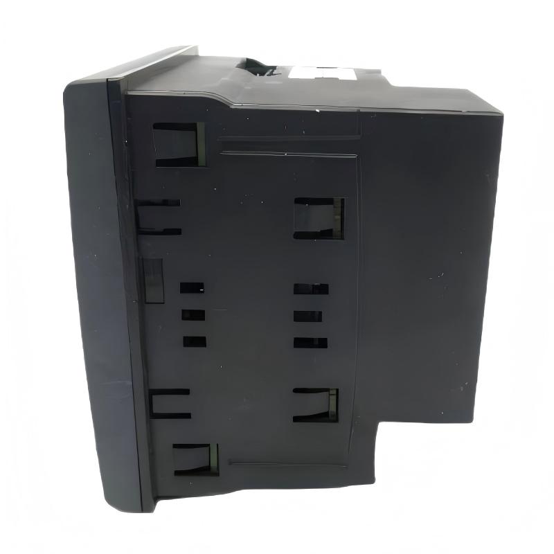
The supplied dimensions are 96 × 72 × 96 mm, while common manufacturer documentation describes the meter as 96 mm wide, 96 mm high, and 72 mm deep.
Confirm the panel cutout, installation depth, clearance, and terminal access requirements using the manufacturer’s mechanical drawing. Ensure that the mounting location is appropriate for the meter’s environmental and temperature ratings.
5. Configure Modbus Communication
For RS-485 communication, configure the baud rate, parity, stop bits, and device address consistently across the meter and the supervisory system.
Use suitable twisted-pair communication cable and follow the recommended grounding, shielding, and termination practices for the network topology. Avoid creating unnecessary branches or wiring arrangements that degrade signal quality.
When commissioning, verify communication with a known measurement such as phase voltage or current before configuring larger data collections.
6. Verify Measurements During Commissioning
After installation, compare representative voltage and current readings with a suitable reference instrument. Check the phase association, CT ratio, power factor, active power, and energy accumulation.
Unexpected negative power, imbalanced phase readings, or implausible power factor values may indicate incorrect CT polarity, phase mismatch, or an unsuitable configuration.
Record the final configuration and communication settings so that the installation can be maintained consistently.
Compatible System Components
The METSEPM5310 typically operates as part of a broader electrical monitoring system. The following components may be used with it, depending on the application.
| Component | Function | Integration Considerations |
|---|---|---|
| Current transformers | Provide current signals to the meter | Match 1 A or 5 A secondary rating and configure the CT ratio |
| Voltage measurement circuits | Supply voltage signals for measurement | Follow the meter’s network configuration and voltage limits |
| PLC | Uses meter data in automation logic | Verify RS-485/Modbus support and register mapping |
| SCADA system | Displays and records electrical measurements | Configure polling, data types, scaling, and alarms |
| Energy management software | Analyzes energy consumption | Confirm data collection intervals and reporting requirements |
| RS-485 communication cable | Connects the meter to compatible devices | Follow network wiring, shielding, and termination guidelines |
| Circuit breakers and fuses | Protect electrical circuits | Select independently according to system design and applicable codes |
| Electrical distribution panel | Houses the meter and monitored circuits | Verify cutout, mounting depth, environmental conditions, and clearances |
| Supervisory gateway | Connects RS-485 data to another network | Verify protocol conversion and register compatibility |
These are typical integration components, not a statement that accessories are included with the meter.
Alternative Models and Replacement Considerations
The PowerLogic PM5000 family contains multiple meters with different measurement, communication, and monitoring capabilities. A replacement should be chosen according to the actual application rather than the appearance of the front display alone.
| Alternative Model or Category | Key Considerations |
|---|---|
| Schneider Electric PowerLogic PM5110 | Consider for applications requiring a different feature set or monitoring configuration; verify exact measurement and communication capabilities |
| Schneider Electric PowerLogic PM5320 | A related PM5000-series meter; compare display, measurement, I/O, and communication specifications |
| Schneider Electric PowerLogic PM5330 | May be considered for applications requiring broader monitoring features, subject to detailed specification checks |
| Schneider Electric PowerLogic PM5340 | A related multifunction meter option; verify the exact catalog number and required functions |
| Other multifunction power meters | Can be considered if measurement accuracy, input ratings, communications, and mounting requirements are satisfied |
Before replacing the METSEPM5310, compare the following:
- Voltage measurement ranges and supported network configurations.
- Current-transformer secondary rating and CT ratio settings.
- Active energy accuracy class.
- Harmonic measurement requirements.
- Modbus register mapping and communication settings.
- Digital input and output requirements.
- Alarm and data-recording capabilities.
- Panel cutout, depth, and terminal arrangement.
- Applicable certifications and local metering requirements.
A replacement may require changes to wiring, SCADA register maps, alarm configuration, or energy reporting logic. Verify compatibility before removing an installed meter.
Key Advantages
Multifunction Electrical Measurement
The meter consolidates measurements of voltage, current, power, energy, frequency, and power factor in one panel-mounted instrument.
Harmonic Analysis
Analysis up to the 31st harmonic can help identify electrical distortion that may require further investigation.
Modbus Communication
The RS-485 interface and Modbus RTU/ASCII support allow compatible supervisory systems to collect measurements for monitoring and reporting.
Digital Inputs and Outputs
Two digital inputs and two digital outputs support selected monitoring and integration functions, subject to the meter’s configuration and documented capabilities.
Configurable Alarms
The meter supports configurable alarms that can help notify operators of selected electrical conditions.
Data Recording
Internal memory and event-recording functions support selected monitoring and diagnostic tasks, depending on configuration.
Panel-Mounted Display
The LCD display provides local access to electrical measurements without requiring a computer or supervisory workstation for every inspection.
Energy Management Support
Measured values can be used to analyze energy consumption across feeders, departments, or equipment groups when integrated into a suitable monitoring system.
Technical FAQs
1. What is the Schneider Electric METSEPM5310?
The METSEPM5310 is a PowerLogic PM5000 multifunction power meter. It measures electrical parameters such as voltage, current, frequency, power factor, active and reactive power, and energy.
2. What communication protocol does it support?
It supports Modbus RTU and Modbus ASCII over a two-wire RS-485 interface. The communication settings and register mapping must be configured to match the connected supervisory system.
3. Can it monitor a three-phase electrical system?
Yes. The meter supports three-phase configurations, including three-phase with neutral. Correct network configuration and voltage and CT wiring are essential.
4. Does it require current transformers?
For current measurement in installations using external CTs, the meter requires CT secondary signals compatible with its 1 A or 5 A current inputs. The CT ratio must be configured correctly.
5. What electrical parameters can it measure?
It can measure voltage, current, frequency, power factor, active power, reactive power, and energy. It also supports harmonic analysis up to the 31st harmonic.
6. What does Class 0.5S mean?
Class 0.5S is an active energy measurement accuracy classification under the applicable IEC standard. It describes the meter’s energy measurement performance under specified test conditions; it does not mean that every measurement has an unconditional error of exactly 0.5%.
7. Can the meter connect to a PLC or SCADA system?
Yes, if the PLC or supervisory system supports the appropriate Modbus communication interface and register configuration. A suitable RS-485 connection or gateway may be required.
8. Is the METSEPM5310 a protective relay?
No. It is a measurement and monitoring instrument. It does not replace circuit breakers, fuses, protective relays, or other equipment required for electrical protection.
9. What should be checked before replacing an existing meter?
Verify the full model number, voltage and current inputs, network type, CT ratios, communication protocol, digital I/O requirements, panel dimensions, and software register mapping.
10. What are the dimensions and weight of this model?
The supplied listing dimensions are 96 × 72 × 96 mm, and the supplied weight is 0.43 kg. Manufacturer documentation commonly presents the dimensions as 96 mm wide × 96 mm high × 72 mm deep and lists a net weight of approximately 430 g.
Procurement and Maintenance Recommendations
When sourcing the Schneider Electric METSEPM5310, confirm the complete model number and check that the meter’s voltage inputs, current-transformer rating, communication interface, and digital I/O match the intended installation.
For replacement projects, record the existing CT ratios, network configuration, Modbus address, communication settings, and relevant register assignments before removing the old meter. This information can reduce commissioning time and help prevent reporting errors.
For units already in service, periodically inspect terminal connections, communication wiring, panel conditions, and the accuracy of representative measurements. Any electrical testing should be performed by qualified personnel using appropriate procedures and instruments.
If readings are used for energy cost allocation, internal billing, or compliance reporting, confirm that the metering arrangement satisfies the applicable requirements. The meter’s published accuracy class should be interpreted according to its specified conditions and intended use.
During system integration, maintain a record of register mappings, scaling factors, alarm thresholds, and data collection intervals. This documentation supports troubleshooting and makes future meter replacement or system upgrades more straightforward.
Conclusion
The Schneider Electric METSEPM5310 PowerLogic PM5310 Power Meter is a multifunction electrical measurement device for industrial power distribution, energy monitoring, and facility management. It measures voltage, current, power, energy, frequency, and power factor, and supports harmonic analysis up to the 31st harmonic.
With Modbus RTU/ASCII over RS-485, two digital inputs, two digital outputs, configurable alarms, and data-recording capabilities, it can provide useful electrical information to compatible PLC, SCADA, and energy management systems.
For successful installation and reliable measurement, users should verify the electrical network configuration, CT ratios, communication settings, mounting dimensions, and applicable safety requirements. Correct configuration helps ensure that the meter’s data is useful for operational monitoring, energy analysis, and maintenance planning.