

ProductPRODUCT
Featured products
Contact Us
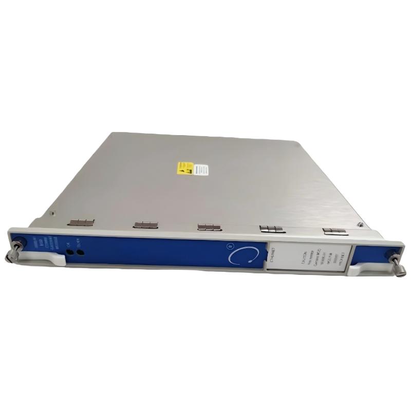
- Bently Nevada
- 3500/92-04-01-00
- Communication Gateway Module
- USA
- 241 × 24.4 × 242 mm
- 0.82kg
- Xiamen, China
- New & In Stock
- T/T, PayPal, Western Union
- 1 Year
- 1-3 Working Days
- DHL, UPS, TNT, FedEx and EMS.
- 24-Hour Service
- COO
- 3
Our advantage

Global Logistics
We have a 10-year logistics and express cooperation agreement, so our products can be shipped to any place in the world.

Brand new and original
Our products are imported in bulk from the place of origin. Because of the cooperative relationship, our products are all original and 100% new.

24-hour service
We provide 7*24 hours service to our customers. We will be there whenever you need us.

Price advantage
All our products are priced very favorably because we have our own warehouse and supply.
| Company Information | |||
| [email protected] | |||
| Mobile | +8615980777398 | ||
| +8615980777398 | |||
| 15980777398 |
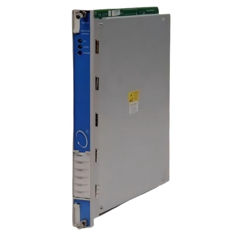
Bently Nevada 3500/92-04-01-00 Communication Gateway Module
1. Product Overview
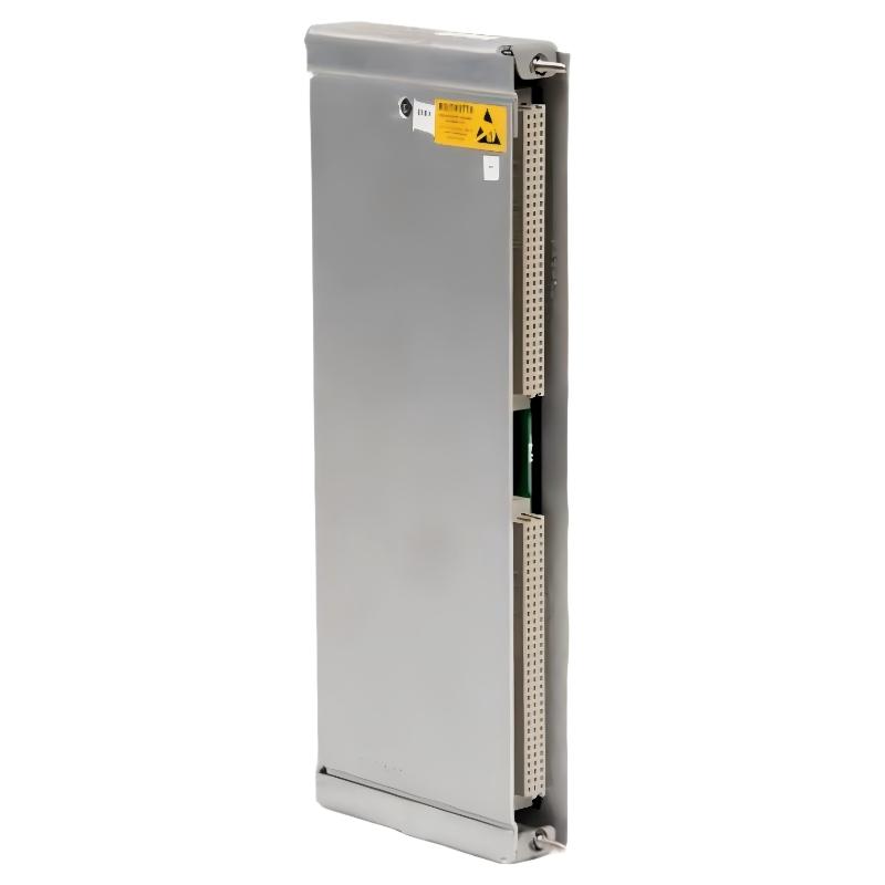
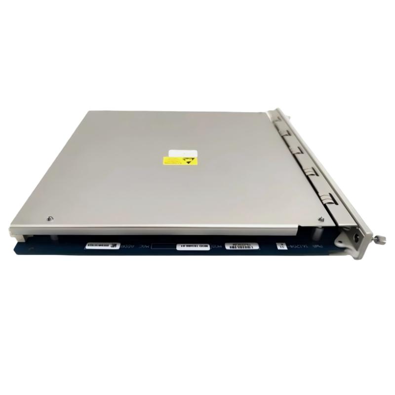
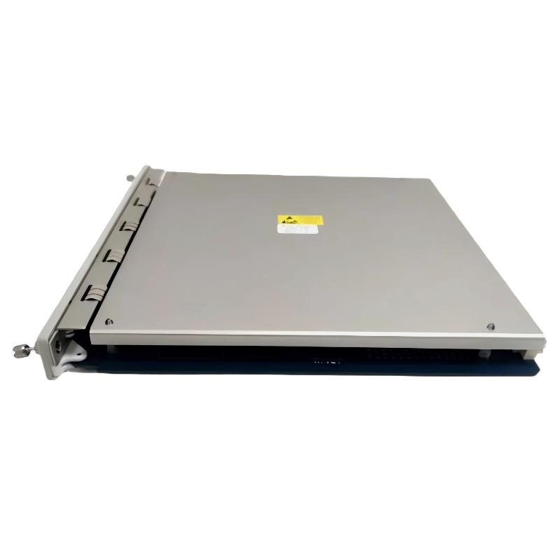
The Bently Nevada 3500/92-04-01-00 is a communication gateway module designed for the 3500 Series machinery protection and condition monitoring system. Its main purpose is to transfer supported measurement values, alarm information, and module status data from a compatible 3500 rack to external control systems, supervisory computers, and industrial data acquisition platforms.
In industrial plants, critical rotating machinery such as steam turbines, gas turbines, compressors, pumps, and generators often operates continuously under demanding conditions. Monitoring systems collect information that helps operators assess equipment condition, review alarms, and identify abnormal operating behavior. The 3500/92 gateway provides a communication path that makes selected rack information available to compatible external systems.
This model uses the Ethernet/RS485 Modbus I/O configuration. It is intended for installations where machinery monitoring data needs to be exchanged with compatible host systems over Ethernet or serial communication. Its low-memory option is part of the module’s ordering configuration and should be matched when replacing an existing unit.
The 3500/92 is not a standalone vibration sensor or measurement monitor. It does not independently measure shaft displacement, vibration, or temperature. These measurements are obtained by compatible sensors and monitoring modules installed in the rack. The gateway’s role is to communicate supported information from the monitoring system to other equipment.
The complete model number, 3500/92-04-01-00, is important when selecting a replacement because each part of the ordering code identifies a particular configuration. The I/O option, memory option, and approval option should all be checked against the installed module before purchase or commissioning.
2. Brand and Product Series
| Item | Description |
|---|---|
| Brand | Bently Nevada |
| Product series | 3500 Series |
| Product name | Communication Gateway Module |
| Model number | 3500/92-04-01-00 |
| Product category | Machinery protection system communication module |
| Main function | Transfers supported rack data to compatible external systems |
| I/O configuration | Ethernet / RS485 Modbus |
| Memory configuration | Low memory |
| Agency approval option | No additional agency approval option indicated by 00 |
| Installation type | Modular rack installation |
| Typical system role | Interface between the monitoring rack and external automation or data acquisition systems |
| Typical application | Machinery monitoring, industrial communication, and centralized equipment data access |
3. Technical Parameters
The table below summarizes the commonly specified configuration. Confirm the exact hardware revision and rear I/O assembly before using the figures for replacement, cabinet design, or procurement.
| Parameter | Specification |
|---|---|
| Model | 3500/92-04-01-00 |
| Brand | Bently Nevada |
| Product series | 3500 Series |
| Module type | Communication gateway |
| I/O option | Ethernet/RS485 Modbus |
| Memory option | Low memory |
| Approval option | 00 — None |
| Ethernet connector | RJ45 |
| Ethernet interface | 10BASE-T |
| Ethernet data rate | 10 Mbps |
| Ethernet standard | IEEE 802.3 |
| Serial interface | RS485 |
| Serial communication protocol | Modbus RTU |
| Ethernet communication protocol | Modbus/TCP |
| Additional protocol support | Proprietary protocol for compatible rack configuration and data acquisition software |
| Main board dimensions (H × W × D) | Approx. 241 × 24.4 × 242 mm |
| Main board weight | Approx. 0.82 kg |
| Rear I/O module dimensions (H × W × D) | Approx. 241 × 24.4 × 99.1 mm |
| Rear I/O module weight | Approx. 0.44 kg |
| Combined hardware weight | Approx. 1.26 kg |
| Typical power consumption | Approx. 5.6 W for the RS485 I/O configuration |
| Operating temperature | −30°C to +65°C |
| Storage temperature | −40°C to +85°C |
| Relative humidity | Up to 95%, non-condensing |
| Front-panel indicators | OK and TX/RX |
| Front rack space | One full-height front slot |
| Rear rack space | One full-height rear I/O slot |
| Power supply | Supplied through a compatible 3500 rack |
| Primary function | Communication of supported measurements, alarms, and status data |
Dimensions and weight: The main board and rear I/O module are separate components, so their dimensions should not be treated as one combined enclosure size. The combined hardware weight is approximately 1.26 kg. Packaging, mounting accessories, and shipping materials can increase the total shipping weight.
Communication compatibility: The Ethernet/RS485 interface should be matched to the existing plant network and serial wiring. An Ethernet/RS232 variant is not automatically interchangeable, even when it belongs to the same product family.
4. Product Introduction
4.1 Communication Gateway Function
The 3500/92-04-01-00 serves as a communication bridge between the 3500 machinery monitoring rack and compatible external systems. The rack may contain several types of monitoring modules, each responsible for specific measurement, alarm, or diagnostic functions. The gateway collects supported information from the rack’s internal communication architecture and makes it available to external equipment.
This arrangement allows operators to access machinery monitoring information from a central control room or supervisory platform. Instead of checking every monitoring module individually, authorized personnel can use compatible host software to review selected measurements, module conditions, and alarm states.
The gateway is especially useful in plants where machinery protection systems need to exchange information with the wider automation infrastructure. It complements the monitoring rack rather than replacing the functions of its measurement and protection modules.
4.2 Ethernet Communication
The Ethernet interface uses an RJ45 connector and supports 10BASE-T networking at 10 Mbps. It provides a connection for compatible host systems and supports Modbus/TCP as well as the applicable proprietary communication protocol.
Ethernet communication can simplify the integration of machinery monitoring data into a plant network. However, the gateway must be configured correctly, and the host system must support the relevant communication method. Network addressing, cabling, access permissions, and data mapping should be checked during commissioning.
4.3 RS485 Serial Communication
The 04 I/O configuration includes an RS485 serial interface. This interface supports serial Modbus communication and is suitable for compatible industrial devices that use an RS485 connection.
RS485 uses differential signaling and is widely used for industrial communication. Its reliability depends on correct wiring, suitable cable, proper termination, appropriate grounding, and the network topology. The receiving controller must also use matching serial communication settings.
The RS485 interface is particularly relevant when the existing control system relies on serial Modbus rather than exclusively Ethernet-based communication.
4.4 Modbus Protocol Support
Modbus provides a standardized way for compatible controllers and monitoring platforms to read configured information from the gateway. Depending on the rack configuration, supported data may include measurement values, alarm states, and module status information.
The actual data available to an external system depends on the installed monitor modules, channel configuration, gateway setup, and register mapping. For a new installation, the required register list should be defined and verified during commissioning.
The gateway should not be assumed to expose every value from every rack module automatically. Proper configuration is necessary to ensure that the host system reads the intended data and interprets it correctly.
4.5 Low-Memory Configuration
The 01 portion of the model number identifies the low-memory configuration. This is an ordering characteristic that should be matched when replacing an existing module.
Memory configuration is only one aspect of compatibility. The I/O option, hardware revision, rear I/O module, rack arrangement, and system configuration must also be considered.
For maintenance projects, it is advisable to compare the full model number on the existing unit with the proposed replacement before placing an order.
4.6 Status Indicators and Troubleshooting
The front-panel indicators provide a convenient initial check of the module’s condition and communication activity.
| Indicator | General purpose | Maintenance use |
|---|---|---|
| OK | Indicates the module’s general operating status | Helps identify an apparent module health issue |
| TX/RX | Indicates communication activity | Helps determine whether communication activity is occurring |
| Ethernet connection | Provides the physical network interface | Check the cable, switch port, and host network settings |
| RS485 connection | Provides the serial communication interface | Check polarity, termination, addressing, and serial settings |
The indicators provide useful diagnostic clues, but they cannot confirm every aspect of communication performance. A module may appear operational while the host system still has an incorrect IP configuration, register map, or serial communication setting.
A complete troubleshooting process should therefore include both module-level checks and end-to-end verification of the data received by the host system.
5. Product Applications
5.1 Steam and Gas Turbines
Turbines are essential assets in power generation and many industrial processes. Machinery monitoring systems may collect vibration, shaft position, speed-related, and alarm information through compatible sensors and monitoring modules.
The 3500/92 gateway can transfer supported information to compatible plant systems. This allows operators to review machinery monitoring data alongside process values and other operating information.
Its role is communication and integration; it does not independently perform the underlying vibration or shaft-position measurements.
5.2 Industrial Compressors
Compressors are commonly used in gas processing, petrochemical production, pipeline systems, and manufacturing facilities. Their continuous operation often makes reliable condition monitoring important for maintenance planning and production continuity.
The gateway can make supported compressor monitoring data available to external systems. This helps plant personnel review selected equipment values and alarm conditions through a centralized interface.
5.3 Pumps and Motor-Driven Equipment
Large pumps and motor-driven equipment are widely used in process plants, utilities, and industrial production lines. Depending on the installed monitoring arrangement, relevant measurements and status information may be available from the 3500 rack.
The 3500/92 can transfer this supported information to a compatible host system, helping maintenance personnel review operating conditions and investigate reported abnormalities.
5.4 Power Generation Facilities
Power stations use machinery protection and condition monitoring systems to support the operation of turbines, generators, and auxiliary rotating equipment.
The gateway can form part of the communication architecture connecting a machinery monitoring rack with a supervisory computer or compatible plant automation system. This makes selected monitoring information accessible beyond the local rack.
5.5 Oil and Gas Facilities
Oil and gas production, gas compression, pipeline, and processing facilities frequently use centralized control rooms to monitor critical equipment.
The 3500/92 can support the transfer of configured machinery monitoring data to compatible external systems. The precise integration depends on the site’s network design, serial communication requirements, and host system capabilities.
5.6 Petrochemical and Chemical Plants
In chemical and petrochemical production, rotating equipment may operate under demanding process conditions and require continuous monitoring.
The gateway can help make supported measurements, alarm states, and module status information available to centralized monitoring platforms. This allows equipment information to be considered alongside other plant operating data.
5.7 Centralized Condition Monitoring
When a facility has multiple monitored assets, consolidating selected machinery data can simplify day-to-day equipment supervision.
The 3500/92 supports this approach by providing a communication interface between the monitoring rack and compatible external systems. The host platform can then display, store, or process the data according to its own capabilities and configuration.
5.8 Industrial Maintenance and Diagnostics
Maintenance personnel often need access to equipment measurements and alarm histories when investigating operating abnormalities. Where the required data is available and correctly configured, the gateway can help make this information accessible through a compatible supervisory or data acquisition system.
The gateway does not automatically diagnose all equipment faults. It supports the transfer of information that engineers can use with the appropriate monitoring tools and maintenance procedures.
6. Product Advantages
6.1 Connects Machinery Monitoring with Plant Automation
The primary advantage of the 3500/92 is its ability to transfer supported rack information to external systems. This helps bridge the gap between machinery protection equipment and the wider plant automation environment.
It allows selected machinery data to be used by compatible supervisory and data acquisition platforms without requiring the gateway itself to perform the original measurement.
6.2 Provides Ethernet and RS485 Interfaces
The Ethernet/RS485 configuration supports two widely used industrial communication methods. Ethernet provides network-based communication, while RS485 supports serial Modbus integration.
This combination can be useful in facilities where different parts of the automation system use different communication architectures.
6.3 Supports Industrial Communication Protocols
The gateway supports Modbus RTU over serial communication and Modbus/TCP over Ethernet. These protocols are commonly used for data exchange between compatible industrial devices.
The availability of established protocols can simplify integration, although correct register mapping and communication settings remain essential.
6.4 Helps Centralize Equipment Information
By transferring supported rack data to an external host, the gateway can help operators access selected measurements, alarm conditions, and status information from a centralized location.
This can make machinery information easier to review during normal operation and maintenance activities.
6.5 Modular Rack Design
The module is designed for installation in a compatible 3500 rack. Its modular form allows the communication function to be incorporated into an existing machinery monitoring system.
The separate rear I/O hardware provides the relevant physical communication connections for the selected configuration.
6.6 Convenient Status Indicators
The OK and TX/RX indicators provide a quick visual reference during maintenance and commissioning. They can help technicians identify apparent module or communication activity issues before carrying out more detailed checks.
6.7 Supports Maintenance Workflows
Centralized access to supported machinery data can assist engineers when reviewing alarms, investigating equipment abnormalities, and planning maintenance.
The gateway provides the communication path. Effective diagnosis still depends on the quality of the underlying measurements, the host system, and the engineer’s interpretation of the available information.
6.8 Suitable for Existing 3500 Installations
For facilities already using the 3500 Series, the 3500/92 can provide a practical way to connect rack data with compatible external systems.
This makes it relevant to system integration projects, replacement work, and upgrades where the existing machinery monitoring platform is being retained.
7. Five Related Models in the Same Series
The following models perform complementary functions within the 3500 Series. They may be relevant when expanding or maintaining a machinery monitoring rack, but they are not direct replacements for the 3500/92 communication gateway.
The dimensions and weights shown are approximate planning values for common module formats. Verify the precise hardware revision and configuration before procurement.
| Model | Product name | Main function | Typical dimensions (H × W × D) | Approx. weight (kg) |
|---|---|---|---|---|
| 3500/22M | Transient Data Interface | Provides a rack data interface and transient data functions | Approx. 241 × 24.4 × 242 mm | Approx. 0.91 |
| 3500/25 | Keyphasor Module | Processes Keyphasor signals for speed and phase-related measurements | Approx. 241 × 24.4 × 242 mm | Approx. 0.91 |
| 3500/32M | Four-Channel Relay Module | Provides relay outputs for configured alarm and control logic | Approx. 241 × 24.4 × 242 mm | Approx. 0.91 |
| 3500/40M | Proximitor Monitor | Monitors compatible proximity-probe inputs | Approx. 241 × 24.4 × 242 mm | Approx. 0.91 |
| 3500/42M | Proximitor/Seismic Monitor | Supports configured vibration and position monitoring functions | Approx. 241 × 24.4 × 242 mm | Approx. 0.91 |
7.1 Model Descriptions
3500/22M — Transient Data Interface
The 3500/22M provides data interface and transient data functions within a compatible monitoring system. It may be relevant where transient data handling is required in addition to the gateway’s communication role.
3500/25 — Keyphasor Module
The 3500/25 processes Keyphasor signals used for rotational speed and phase-related measurements. These signals can be important when interpreting vibration behavior and understanding the rotational condition of monitored machinery.
3500/32M — Four-Channel Relay Module
The 3500/32M provides relay outputs for configured alarm and control functions. It may be selected when an installation requires relay-based signaling to external equipment or compatible control circuits.
3500/40M — Proximitor Monitor
The 3500/40M monitors compatible proximity-probe inputs. Depending on the configuration, it supports measurements associated with shaft vibration and position.
3500/42M — Proximitor/Seismic Monitor
The 3500/42M supports configured vibration and position monitoring functions. The exact measurement capabilities depend on the installed module configuration and compatible sensor arrangement.
These related modules serve different purposes. The communication gateway transfers supported data, whereas monitoring and relay modules perform their respective measurement, signal processing, or output functions.
8. Five Popular Models from the Same Brand
The following models cover several common functions in machinery protection and condition monitoring systems, including power supply, data interfacing, vibration monitoring, and communication.
| Model | Product name | Main function | Typical dimensions (H × W × D) | Approx. weight (kg) |
|---|---|---|---|---|
| 3500/15 | Power Supply Module | Supplies power to compatible 3500 rack modules | Approx. 241 × 24.4 × 242 mm | Approx. 0.91 |
| 3500/22M | Transient Data Interface | Provides rack data interface and transient data functions | Approx. 241 × 24.4 × 242 mm | Approx. 0.91 |
| 3500/40M | Proximitor Monitor | Monitors compatible proximity-probe inputs | Approx. 241 × 24.4 × 242 mm | Approx. 0.91 |
| 3500/42M | Proximitor/Seismic Monitor | Supports configured vibration and position monitoring | Approx. 241 × 24.4 × 242 mm | Approx. 0.91 |
| 3500/92 | Communication Gateway | Transfers supported rack data to external systems | Main board: 241 × 24.4 × 242 mm; rear I/O: 241 × 24.4 × 99.1 mm | Approx. 1.26 combined |
Specification note: The related-module figures are approximate and intended for preliminary comparison. Module versions, connectors, and associated hardware can affect physical specifications. The 3500/92 weight shown is the combined weight of its main board and rear I/O module, not the weight of the main board alone.
8.1 Model Selection Guidance
– 3500/15: Consider this module when reviewing the rack power supply arrangement. Its function is different from the communication gateway.
– 3500/22M: Consider this model when the system requires the associated data interface and transient data functions.
– 3500/40M: Consider this model when compatible proximity-probe measurement and monitoring functions are required.
– 3500/42M: Consider this model for supported vibration and position monitoring applications.
– 3500/92: Consider this model when the main requirement is communication of supported rack data to external systems.
The best choice depends on whether the requirement concerns power, measurement, data handling, relay output, or external communication.
9. Comparison with Other Module Types
| Comparison item | 3500/92-04-01-00 | 3500/40M or 3500/42M | 3500/32M |
|---|---|---|---|
| Primary role | Communication gateway | Machinery monitoring | Relay output |
| Measures vibration directly | No | Yes, for supported inputs and configurations | No |
| Processes compatible sensor signals | Not its main function | Yes | Not its main function |
| Transfers supported rack data externally | Yes | Not its main function | Not its main function |
| Provides relay outputs | No, not its main function | Not its main function | Yes |
| Ethernet/Modbus integration | Main purpose of this configuration | Depends on the wider system architecture | Depends on the wider system architecture |
| Typical reason for selection | External data access and integration | Machinery measurement and monitoring | Alarm and control signaling |
This distinction matters when diagnosing problems. If the host system is not receiving machinery data, the gateway, network, serial wiring, and register configuration should be checked. If a measurement is missing or abnormal at its source, the relevant sensor, wiring, and monitoring module should also be investigated.
10. Installation and Configuration Considerations
Before installing or replacing the 3500/92-04-01-00, the following checks are recommended.
1. Confirm the full model number. Check the existing unit’s complete order code and ensure the replacement has the required configuration.
2. Verify the Ethernet/RS485 option. The 04 option identifies the Ethernet/RS485 Modbus configuration. An RS232-based variant should not be substituted without confirming system compatibility.
3. Check the rear I/O hardware. Verify that the I/O assembly matches the main module and the intended communication interfaces.
4. Review Ethernet settings. Confirm the network address, cabling, host configuration, and required communication protocol.
5. Inspect RS485 wiring. Check the A/B signal connections, cable quality, termination, shielding, grounding, and serial communication settings.
6. Verify the Modbus register map. Confirm that the host reads the intended register addresses and correctly interprets the returned values.
7. Confirm rack and environmental compatibility. Check the required slot arrangement, power availability, operating temperature, and installation clearances.
8. Perform end-to-end testing. Confirm that the module reports a normal status and that the host receives valid data through the required communication interface.
Because the gateway is part of a machinery monitoring system, installation and commissioning should follow the site’s approved maintenance procedures. Successful communication alone does not prove that every measurement channel or machinery protection function is operating correctly.
11. Purchasing and Replacement Recommendations
When purchasing a 3500/92-04-01-00, matching the full hardware configuration is more important than relying on the general product name.
| Check item | What to confirm |
|---|---|
| Complete model | 3500/92-04-01-00 |
| I/O configuration | Ethernet/RS485 Modbus |
| Memory configuration | Low memory |
| Approval option | 00 — None |
| Main board dimensions | Approx. 241 × 24.4 × 242 mm |
| Rear I/O module dimensions | Approx. 241 × 24.4 × 99.1 mm |
| Combined hardware weight | Approx. 1.26 kg |
| Power requirement | Confirm the compatible rack power arrangement |
| Communication | Confirm Ethernet and RS485 requirements |
| System compatibility | Check the installed rack and software configuration |
| Commissioning | Verify module status and end-to-end data communication |
For shipping and cabinet planning, distinguish between the main board weight, rear I/O module weight, combined hardware weight, and packaged shipping weight. The combined hardware weight is approximately 1.26 kg; the packaged unit may weigh more.
For replacement projects, it is also sensible to verify the physical connectors, hardware revision, and configuration requirements before removing the installed module. This helps avoid delays caused by receiving a similar-looking unit with an incompatible I/O option.
12. Overall Assessment
The Bently Nevada 3500/92-04-01-00 Communication Gateway Module is designed to connect a compatible 3500 machinery monitoring rack with external industrial automation and data acquisition systems. Its main role is to transfer supported rack measurements, alarm states, and status information to compatible host equipment.
The Ethernet/RS485 Modbus configuration makes it suitable for installations requiring network-based communication alongside serial Modbus integration. When the gateway, host system, and register mapping are correctly configured, it can help make machinery monitoring information available to operators and maintenance teams through a centralized platform.
The most important selection considerations are the complete order code, the Ethernet/RS485 I/O option, the low-memory configuration, and compatibility with the rear I/O assembly. The main board measures approximately 241 × 24.4 × 242 mm and weighs approximately 0.82 kg. The rear I/O module measures approximately 241 × 24.4 × 99.1 mm and weighs approximately 0.44 kg, giving a combined hardware weight of approximately 1.26 kg.
Overall, this model is best suited to existing 3500 monitoring installations that require a communication interface between the machinery monitoring rack and compatible external systems. It supports data access and system integration, while the underlying measurement and machinery protection functions remain the responsibility of the appropriate sensors and monitoring modules.