

ProductPRODUCT
Featured products
Contact Us
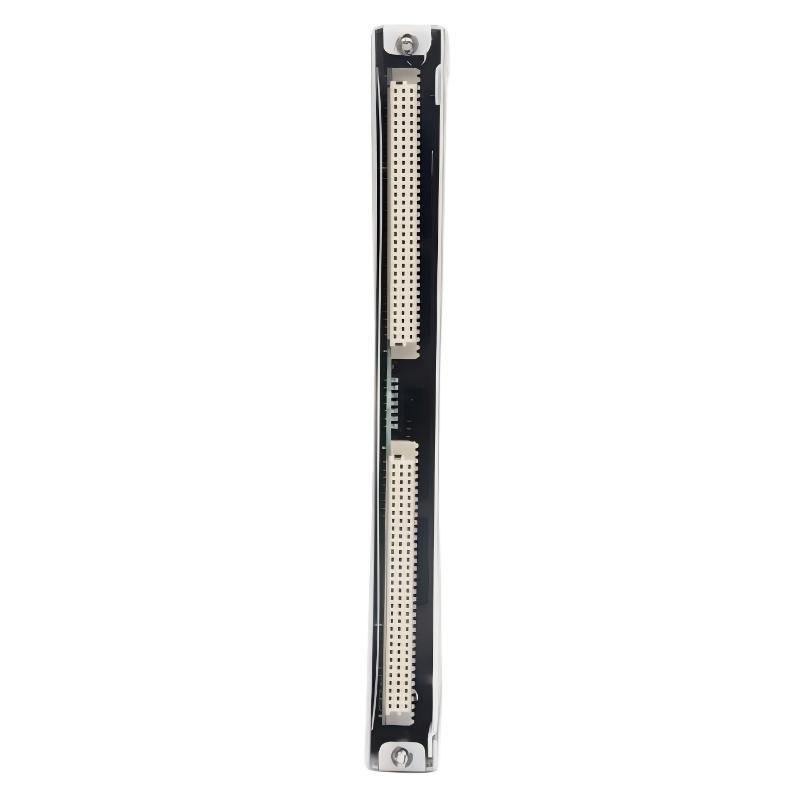
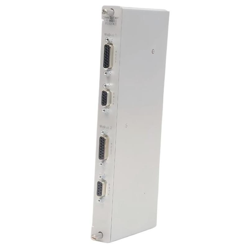
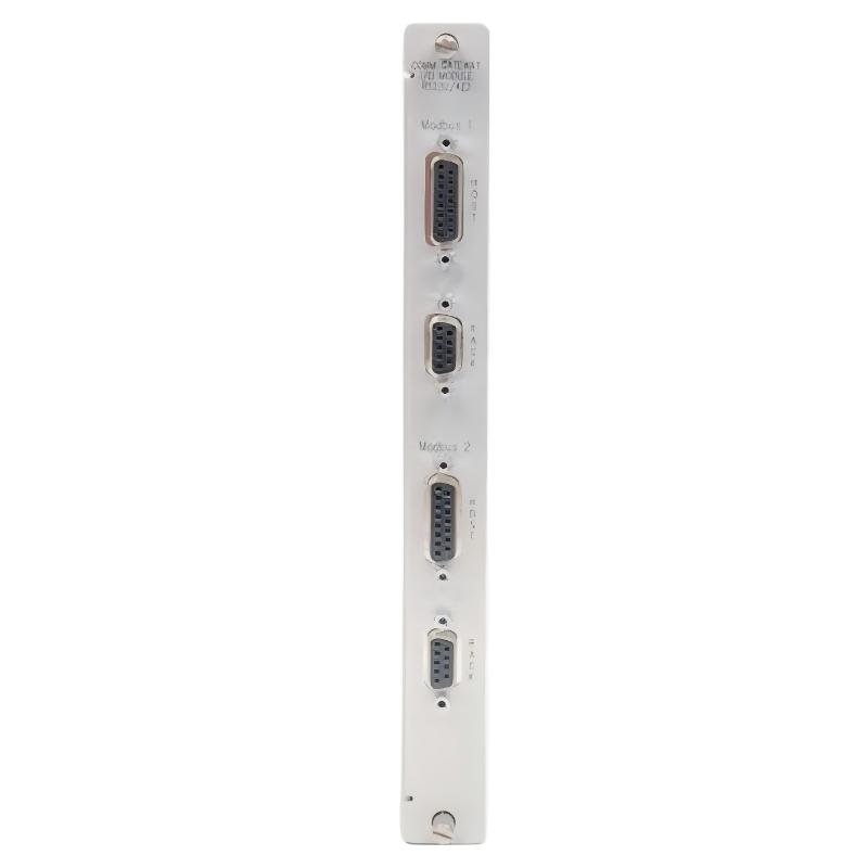
- Bently Nevada
- 3500/92-02-00-00
- Communication Gateway Module
- USA
- 241 × 24.4 × 242 mm
- 0.82kg
- Xiamen, China
- New & In Stock
- T/T, PayPal, Western Union
- 1 Year
- 1-3 Working Days
- DHL, UPS, TNT, FedEx and EMS.
- 24-Hour Service
- COO
- 4
Our advantage

Global Logistics
We have a 10-year logistics and express cooperation agreement, so our products can be shipped to any place in the world.

Brand new and original
Our products are imported in bulk from the place of origin. Because of the cooperative relationship, our products are all original and 100% new.

24-hour service
We provide 7*24 hours service to our customers. We will be there whenever you need us.

Price advantage
All our products are priced very favorably because we have our own warehouse and supply.
| Company Information | |||
| [email protected] | |||
| Mobile | +8615980777398 | ||
| +8615980777398 | |||
| 15980777398 |
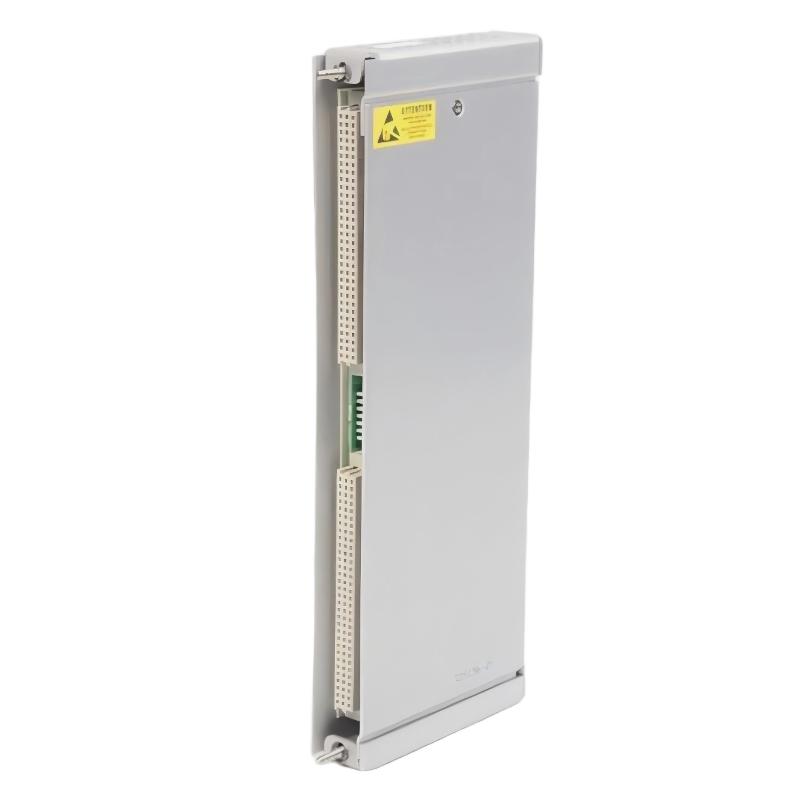
Bently Nevada 3500/92-02-00-00 Communication Gateway
1. Product Overview
The Bently Nevada 3500/92-02-00-00 is a communication gateway model associated with the 3500 Series machinery protection and condition monitoring platform. Its main purpose is to help transfer monitoring data and system status information from a compatible machinery protection rack to external control and supervisory systems.
In industrial plants, critical machinery often operates continuously under demanding conditions. Equipment such as turbines, compressors, pumps, and generators may require ongoing monitoring so that operators can identify abnormal operating conditions and respond appropriately. A communication gateway helps make information collected by the monitoring system accessible to other parts of the plant’s automation infrastructure.
The 3500/92 is not a vibration sensor and does not independently measure shaft displacement or bearing vibration. Instead, it provides a communication function within a larger monitoring arrangement. The measurements themselves are obtained through compatible sensors and monitoring modules installed in the system.
The 02 option is associated with an RS485 Modbus I/O configuration. However, the complete designation 3500/92-02-00-00 should be verified against the unit’s nameplate and ordering documentation before purchasing, because the memory-option code in this designation may not correspond to the standard 3500/92 ordering format. The precise configuration matters when matching a replacement module to an existing installation.
2. Brand and Product Series
| Item | Description |
|---|---|
| Brand | Bently Nevada |
| Product series | 3500 Series |
| Model supplied | 3500/92-02-00-00 |
| Product category | Communication gateway |
| Primary function | Machinery monitoring data communication |
Interface associated with the 02 option |
Modbus RS485 I/O |
| Installation type | Compatible 3500 rack |
| Typical system role | Interface between machinery monitoring equipment and external control or supervisory systems |
| Main application areas | Power generation, petrochemical processing, industrial machinery, compressors, turbines, and pumps |
| System purpose | Improve access to monitoring values, module status, and alarm information |
About the 3500 Series
The 3500 Series is a modular machinery protection and condition monitoring platform. It can be configured with different modules to support vibration measurement, shaft-position monitoring, speed measurement, temperature monitoring, relay outputs, and communication functions.
A typical installation combines the required power supply, rack interface, monitoring modules, and any additional communication or relay modules needed for the application.
The 3500/92 occupies the communication side of this architecture. It helps transfer available information from the monitoring system to external equipment, allowing machinery data to be incorporated into plant-level displays, supervisory systems, and compatible automation applications.
This modular design allows different monitoring functions to coexist in one rack. It also means that replacement parts must be selected according to their specific function, hardware configuration, and compatibility requirements rather than by series name alone.
3. Detailed Technical Parameters
The following specifications describe the standard 3500/92 communication gateway family and the RS485 I/O configuration associated with option 02. Since the complete model number supplied ends in -00-00, its exact memory configuration should be confirmed before ordering.
| Parameter | Technical specification |
|---|---|
| Brand | Bently Nevada |
| Series | 3500 Series |
| Model number supplied | 3500/92-02-00-00 |
| Product name | Communication Gateway |
| Functional category | Machinery protection system communication interface |
I/O configuration associated with 02 |
Modbus RS485 I/O module |
| Standard memory code | 01 — Low Memory |
Standard approval code 00 |
No additional agency approval option |
| Serial communication | Modbus over a supported serial interface |
| RS485 interface | Available with the RS485 I/O configuration |
| Ethernet communication | Available through supported Ethernet I/O configurations |
| Ethernet connector | RJ45 on applicable Ethernet-equipped configurations |
| Ethernet standard | 10BASE-T, IEEE 802.3, on the standard gateway interface |
| Ethernet data rate | 10 Mbps on the standard 10BASE-T interface |
| Supported protocols | Modbus serial, Modbus/TCP, and the system’s proprietary communication protocol, according to hardware configuration |
| Typical power consumption | Approximately 5.6 W with the RS485 I/O configuration |
| Main board dimensions (H × W × D) | 241 × 24.4 × 242 mm |
| Main board weight | Approximately 0.82 kg |
| I/O module dimensions (H × W × D) | 241 × 24.4 × 99.1 mm |
| I/O module weight | Approximately 0.44 kg |
| Combined main board and I/O module weight | Approximately 1.26 kg |
| Front rack requirement | One full-height front slot |
| Rear rack requirement | One full-height rear slot |
| Operating temperature | −30°C to +65°C |
| Storage temperature | −40°C to +85°C |
| Relative humidity | Up to 95%, non-condensing |
| Installation environment | Compatible industrial rack and control cabinet |
| Typical external equipment | PLC, DCS, supervisory computer, or compatible data acquisition system |
| Main data handled | Monitoring values, module status, and alarm status information |
| Replacement requirement | Verify part number, I/O type, memory configuration, approval option, and firmware compatibility |
Physical Dimensions and Weight
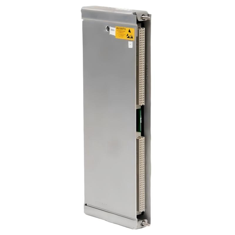
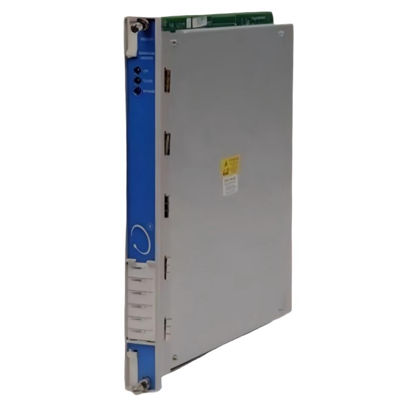
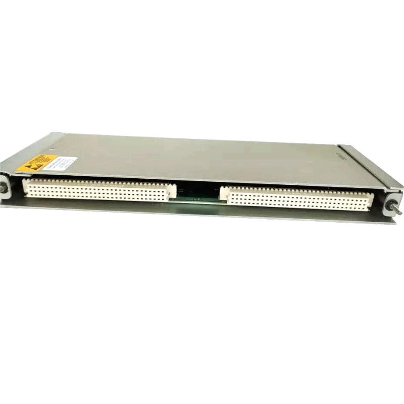
The 3500/92 is made up of a main board installed at the front of the rack and a compatible I/O module installed at the rear. Both parts must be considered when planning installation space or ordering a complete assembly.
| Component | Dimensions (H × W × D) | Weight (kg) | Notes |
|---|---|---|---|
| Main communication module | 241 × 24.4 × 242 mm | 0.82 kg | Front-mounted module |
| RS485 I/O module | 241 × 24.4 × 99.1 mm | 0.44 kg | Rear-mounted module |
| Complete component set | Depends on the fitted configuration | Approx. 1.26 kg | Combined component weight, excluding packaging |
| Shipping package | Varies by supplier and packing method | Not fixed | Must be confirmed for freight calculations |
The dimensions above are nominal component dimensions, not the dimensions of a shipping carton. Packaging weight may differ considerably depending on protective materials, accessories, and the supplier’s packing method.
Communication and Data Handling
The 3500/92 provides a path for transferring information collected by compatible modules in the 3500 rack. This information may include current monitored values, module status, and alarm status.
Its supported communication methods depend on the I/O hardware fitted to the gateway. The RS485 option is intended for compatible serial Modbus applications. Ethernet-based communication requires an appropriate Ethernet-capable configuration.
The available data and its interpretation depend on the rack configuration, the gateway’s register mapping, and the connected control system. For this reason, protocol compatibility should be checked before integrating the gateway into a PLC or DCS network.
4. Product Introduction and Functional Description
The 3500/92 is intended for installations where machinery monitoring information needs to be shared with equipment outside the protection rack. In a large industrial facility, machinery data may be relevant to control-room operators, maintenance teams, process engineers, and condition-monitoring specialists.
Without a suitable communication interface, some information may only be accessible through local configuration tools or other dedicated system interfaces. A gateway provides a structured way to make supported information available to external equipment.
For example, a turbine’s monitoring rack may contain modules that measure vibration and shaft position. Those modules process the sensor signals and provide measurement and status information within the monitoring system. The communication gateway can then make supported information available to an external supervisory system.
This arrangement helps separate three distinct functions:
– Measurement: Sensors and monitoring modules acquire and process machinery-related signals.
– Protection and alarm processing: The configured monitoring system evaluates conditions and provides the relevant status or alarm information.
– Communication: The gateway transfers supported information to compatible external systems.
The 3500/92 primarily performs the third function. It should not be treated as a standalone sensor, a complete machinery protection system, or an automatic substitute for a dedicated shutdown controller.
5. How the Product Works
5.1 Data Collection Inside the Rack
The gateway operates alongside compatible modules in the 3500 rack. These modules may provide vibration, position, speed, temperature, or other measurements, depending on the installed equipment.
The gateway does not generate these measurements itself. Instead, it accesses information made available by the rack and transfers the relevant information through its supported communication interfaces.
5.2 Communication Through the I/O Interface
The installed I/O module determines which physical communication interface is available. With the RS485 option, the gateway can communicate with compatible equipment using the supported serial protocol and correctly configured network parameters.
The communication setup must match the connected device. Common settings to verify include baud rate, parity, device address, wiring polarity, termination, and the register addresses expected by the control system.
5.3 Transfer to the Plant Control System
A compatible PLC, DCS, or supervisory computer can retrieve supported information from the gateway. This can include selected measurement values and status information from the monitoring rack.
The control system must be configured to interpret the received data correctly. An incorrect register map or data format can result in missing, misleading, or incorrectly scaled values even when the physical communication connection is working.
5.4 Display and Operational Use
Once the data is received and interpreted correctly, it can be displayed in a control room or made available to other compatible applications.
Operators can use this information to review equipment status, recognize abnormal indications, and coordinate further investigation with maintenance personnel.
The gateway therefore helps improve access to machinery monitoring information, while the actual interpretation and response remain dependent on the wider control and maintenance arrangements.
6. Product Applications
6.1 Steam Turbine Monitoring
Steam turbines are important assets in power generation and industrial steam systems. Their operating condition can be affected by vibration, shaft position, bearing condition, rotational speed, and changes in load.
When a turbine is monitored by a compatible 3500 system, the 3500/92 can help make supported monitoring information available to external plant systems. This allows operators to review selected machinery information alongside process variables and other operational indications.
The gateway itself does not measure turbine vibration or determine the mechanical cause of an abnormal reading. Those functions depend on the installed sensors, monitoring modules, and engineering analysis.
6.2 Gas Turbine Systems
Gas turbines operate under demanding mechanical and thermal conditions. Reliable access to monitoring information is useful for operators responsible for maintaining stable operation.
The 3500/92 can provide a communication path between a compatible monitoring rack and an external supervisory system. Depending on the installed hardware and configuration, this can make selected monitoring values and alarm states available for centralized review.
6.3 Centrifugal Compressors
Centrifugal compressors are used in refineries, petrochemical plants, gas processing facilities, and other continuous industrial processes.
A compressor monitoring system may collect vibration, shaft-position, speed, and other equipment-related data. The communication gateway can help transfer supported information to a control or supervisory system, making it easier to review machinery condition alongside pressure, temperature, flow, and other process variables.
This can support maintenance investigation and operating decisions, but it does not replace the need for appropriate alarm limits, engineering analysis, or inspection.
6.4 Pumps and Pumping Systems
Large pumps are often critical to production, cooling, circulation, and fluid transfer. An unexpected equipment problem may interrupt a process or require an unplanned shutdown.
Where compatible monitoring equipment is installed, the 3500/92 can help make available machinery monitoring information accessible to the wider plant system. Operators can review the data and coordinate inspection when the system indicates an abnormal condition.
6.5 Power Generation Plants
Power generation facilities contain multiple types of rotating equipment, including turbines, generators, pumps, and auxiliary machinery.
A communication gateway can support centralized access to information from compatible 3500 racks. This is useful where the operating team needs to view selected equipment conditions without relying exclusively on local rack interfaces.
6.6 Refinery and Petrochemical Applications
Refineries and petrochemical plants may operate many critical machines across several process areas. Integrating machinery monitoring information into plant automation systems can help improve visibility across these installations.
The 3500/92 is suitable for this role when the selected communication interface, system configuration, and installation conditions match the requirements of the plant.
6.7 Industrial Condition Monitoring
Condition-monitoring teams often need to review operating data over time to understand changes in machinery behavior. A gateway can help make supported monitoring information available to compatible data acquisition or supervisory systems.
The information may then be used alongside maintenance records, process history, and inspection findings to support equipment assessment.
6.8 Centralized Control-Room Monitoring
In facilities with multiple monitoring racks, centralized communication can reduce the need to access every rack individually for routine status checks.
The 3500/92 can help provide an external view of supported information, subject to the rack configuration and the capabilities of the connected control system.
7. Product Advantages
7.1 Provides a Communication Bridge
The principal advantage of the 3500/92 is its ability to connect machinery monitoring information with compatible external systems.
This makes it possible to present relevant equipment data within the plant’s wider automation environment rather than limiting access to local monitoring interfaces.
7.2 Supports RS485-Based Industrial Integration
The RS485 I/O configuration provides a serial communication interface suitable for compatible industrial applications.
RS485 is widely used in industrial equipment because it supports differential signaling and can be suitable for communication over relatively long cable runs when the network is properly designed.
Actual communication distance and reliability depend on cable selection, wiring topology, termination, grounding, electrical noise, and the specifications of the connected devices.
7.3 Helps Centralize Monitoring Information
The gateway can make supported values and status information available to a common control or supervisory environment.
This can help operators review machinery information alongside process data, alarms, and other plant conditions, improving the convenience of routine monitoring.
7.4 Fits into a Modular System
The 3500/92 is part of a modular monitoring platform. It can operate alongside compatible measurement, monitoring, and rack-interface modules.
This architecture allows the communication function to be integrated into an existing system without replacing every monitoring component, provided the hardware and configuration are compatible.
7.5 Supports Maintenance Investigation
When monitoring data is made available to external systems, maintenance teams can compare equipment indications with process events, operating conditions, and maintenance history.
This can help direct attention toward machinery that requires further investigation. However, the gateway does not independently diagnose mechanical faults; diagnosis requires suitable data and engineering assessment.
7.6 Has a Defined, Specialized Role
The gateway performs a communication function distinct from the measurement and protection functions of other modules.
This separation makes it easier to plan system architecture and identify the correct module type when maintenance or replacement is required.
7.7 Supports Industrial Rack Installation
The main module and rear I/O module are designed for compatible rack installation. This allows the gateway to occupy defined positions within the existing system layout.
Correct slot allocation, wiring, configuration, and environmental conditions are still necessary for reliable operation.
7.8 Helps Improve Operational Visibility
The gateway can help make selected monitoring values and alarm information available to people and systems that need them.
This may improve access to relevant information during normal operation, troubleshooting, and maintenance planning, particularly where machinery monitoring is integrated with the plant’s supervisory systems.
8. Five Related Models in the Same Series or Functional Group
The following five models are related to the 3500/92 by their role in the same machinery monitoring platform. They are not direct substitutes for the communication gateway, because each performs a different function.
Dimensions and weights are approximate reference values for the module family. Exact specifications should be checked against the particular part number and hardware revision.
| Model | Product type | Main parameters and function | Dimensions (H × W × D) | Weight (kg) |
|---|---|---|---|---|
| 3500/22M | Transient Data Interface module | Provides an interface for data access and supported system communication functions | Approx. 241 × 24.4 × 242 mm | Approx. 0.91 |
| 3500/25 | Enhanced Keyphasor module | Processes Keyphasor signals for speed and phase-related monitoring functions | Approx. 241 × 24.4 × 242 mm | Approx. 0.91 |
| 3500/32M | Four-channel relay module | Provides configurable relay outputs for compatible alarm and control applications | Approx. 241 × 24.4 × 242 mm | Approx. 0.91 |
| 3500/40M | Proximitor monitor | Monitors supported proximity-probe input signals | Approx. 241 × 24.4 × 242 mm | Approx. 0.91 |
| 3500/42M | Proximitor/Seismic monitor | Supports selected vibration and position monitoring functions, depending on configuration | Approx. 241 × 24.4 × 242 mm | Approx. 0.91 |
8.1 3500/22M Transient Data Interface
The 3500/22M is associated with data access and interface functions in the 3500 platform. It may be relevant when evaluating the wider system’s data acquisition architecture.
It should not be considered a direct replacement for the 3500/92 without confirming the required function, rack arrangement, and supported communication path.
8.2 3500/25 Enhanced Keyphasor Module
The 3500/25 processes Keyphasor signals that can be used for speed and phase-related measurements. Such signals can be important when evaluating machinery behavior under different operating conditions.
It performs a measurement-support function rather than the gateway’s primary communication function.
8.3 3500/32M Four-Channel Relay Module
The 3500/32M provides relay output capability for compatible system configurations. Relay outputs may be used in alarm or control arrangements designed around the monitoring system.
Its purpose differs from the 3500/92, which is intended to transfer monitoring information to external systems.
8.4 3500/40M Proximitor Monitor
The 3500/40M is a monitoring module for supported proximity-probe signals. Depending on the system configuration, it can be used for shaft-position and related measurement applications.
It may provide data that becomes useful to external supervisory systems through a compatible communication arrangement.
8.5 3500/42M Proximitor/Seismic Monitor
The 3500/42M supports selected vibration and position monitoring applications. It is relevant when reviewing the measurement modules that provide data to the wider 3500 system.
Its compatibility with specific sensors and rack configurations should be verified before use.
9. Five Other Bently Nevada Models for Comparison
These models cover several common functions in the wider machinery monitoring platform. They can be relevant when planning spare parts, upgrading monitoring capability, or reviewing the components installed around a communication gateway.
| Model | Product category | Main function | Typical dimensions (H × W × D) | Weight (kg) |
|---|---|---|---|---|
| 3500/15 | Power supply module | Supplies power to compatible rack components; exact variant matters | Approx. 241 × 24.4 × 242 mm, variant-dependent | Approx. 0.9, variant-dependent |
| 3500/65 | Temperature monitor | Monitors supported temperature input channels | Approx. 241 × 24.4 × 242 mm | Approx. 0.91 |
| 3500/72M | Recip monitor | Supports monitoring of selected reciprocating machinery parameters | Approx. 241 × 24.4 × 242 mm | Approx. 0.91 |
| 3500/40M | Proximitor monitor | Monitors supported proximity-probe signals | Approx. 241 × 24.4 × 242 mm | Approx. 0.91 |
| 3500/42M | Proximitor/Seismic monitor | Supports selected vibration and position monitoring applications | Approx. 241 × 24.4 × 242 mm | Approx. 0.91 |
The weights in this comparison table are approximate, not guaranteed values for every hardware revision. Power supply variants, connectors, and other configuration details may affect the final specification.
10. Comparison Between the 3500/92 and Other Modules
| Comparison item | 3500/92 Communication Gateway | Measurement modules such as 3500/40M | Relay module such as 3500/32M |
|---|---|---|---|
| Primary purpose | Transfer supported monitoring information to external systems | Measure or process supported sensor inputs | Provide relay outputs |
| Direct sensor measurement | No | Yes, for supported input types | No |
| Data communication | Primary function | Depends on the overall system architecture | Not its primary function |
| Alarm-related role | Makes supported status information available externally | Processes monitoring values and configured alarm conditions | Provides relay outputs according to configuration |
| Typical installation | Compatible 3500 rack | Compatible 3500 rack | Compatible 3500 rack |
| Can directly replace the 3500/92? | Correct function, subject to configuration | No | No |
The distinction is important when purchasing spare modules. A module may belong to the same product series but still be unsuitable as a replacement because its function, I/O configuration, and hardware requirements differ.
11. Model Number and Ordering Considerations
The supplied model number is 3500/92-02-00-00. Before ordering, it is worth checking the suffix carefully.
The commonly documented ordering structure for the 3500/92 is:
| Ordering field | Meaning | Common option |
|---|---|---|
| Product family | Communication gateway | 3500/92 |
| I/O module type | Serial or Ethernet communication configuration | 02 = Modbus RS485 I/O |
| Memory type | Memory configuration | 01 = Low Memory |
| Agency approval | Approval option | 00 = None |
In this ordering structure, a commonly specified RS485 configuration with low memory and no additional agency approval is 3500/92-02-01-00.
The model 3500/92-02-00-00 supplied in the request does not match that standard suffix pattern. It may be a transcription error, an incomplete designation, or a nonstandard description used in a particular inventory system. It should not automatically be assumed equivalent to 3500/92-02-01-00.
Before purchasing, confirm the full product label, the rear I/O module’s part number, the required memory option, and any approval requirements. If the part is intended as a replacement for an installed gateway, confirm that the replacement is compatible with the existing rack, firmware, communication settings, and control-system integration.
12. Installation and Maintenance Recommendations
12.1 Verify the Hardware Before Installation
Check the model number on the module and its associated I/O hardware. The main module and rear I/O module should match the intended communication arrangement.
Do not rely solely on the front-panel label if the rear I/O module has been replaced or modified during previous maintenance.
12.2 Check Communication Settings
For an RS485 application, verify the serial communication settings at both ends. These commonly include device address, baud rate, parity, stop bits, wiring polarity, and termination.
The external PLC or DCS must also use the correct register mapping and data interpretation.
12.3 Review Cable Routing and Grounding
Industrial electrical environments can produce interference that affects communication. Suitable cable selection, proper routing, correct termination, and an appropriate grounding arrangement can help reduce communication problems.
12.4 Confirm Rack and Environmental Compatibility
Before installation, verify the rack slot requirements and the permitted environmental conditions. The nominal dimensions and weight are useful for planning, but they do not replace the need to confirm the precise module configuration.
12.5 Test the Data After Replacement
After installation, confirm that the external control system can communicate with the gateway and retrieve the expected information.
Check that measurement values, alarm statuses, and module states are correctly interpreted. A successful communication test alone does not prove that the data mapping or engineering units are correct.
12.6 Keep Configuration Records
Record the installed model, I/O module part number, communication settings, register map, firmware information, and any relevant configuration changes.
These records can simplify future replacement work and reduce the likelihood of configuration errors during maintenance.
13. Purchasing and Spare-Part Selection Guide
When selecting a replacement or spare 3500/92, the most important consideration is whether the proposed unit matches the required system configuration.
The following checklist can help structure the purchasing process.
| Checkpoint | What to confirm | Why it matters |
|---|---|---|
| Exact model number | Full suffix and nameplate details | Prevents ordering the wrong configuration |
| I/O module | RS485, RS232/RS422, or Ethernet variant as required | Determines physical interface compatibility |
| Memory option | Confirm the correct memory code | Avoids a mismatch between the ordered model and intended configuration |
| Approval option | Confirm whether the installation requires specific approvals | Ensures suitability for the installation environment |
| Rack compatibility | Confirm the required rack and slot arrangement | Prevents installation problems |
| Firmware | Confirm compatibility with the existing system | May affect communication or configuration functions |
| Protocol configuration | Confirm Modbus and register-map requirements | Ensures the external system interprets data correctly |
| Dimensions and weight | Check main board and rear I/O module separately | Supports cabinet planning and shipping calculations |
| Physical condition | Inspect connectors, board condition, and module identification | Helps avoid installation of unsuitable hardware |
| Documentation | Obtain the correct technical information for the supplied revision | Supports installation, configuration, and maintenance |
For critical machinery, the replacement should be selected on technical compatibility rather than appearance alone. Two modules may look similar but differ in communication interfaces, firmware requirements, or ordering options.
14. Overall Product Assessment
The Bently Nevada 3500/92 is a specialized communication gateway designed to connect supported machinery monitoring information with compatible plant automation and supervisory systems.
Its value lies in making selected monitoring values and status information available outside the rack. In a properly configured installation, this can support centralized monitoring, maintenance investigation, and integration between machinery protection equipment and the wider plant control environment.
The RS485 I/O option is particularly relevant to installations that use serial Modbus communication. However, the actual communication capability depends on the installed I/O hardware and the configuration of the connected equipment.
The main board has nominal dimensions of 241 × 24.4 × 242 mm and a typical weight of 0.82 kg. The compatible rear I/O module has nominal dimensions of 241 × 24.4 × 99.1 mm and a typical weight of 0.44 kg. Together, the two components weigh approximately 1.26 kg, excluding packaging and accessories.
The five related models and five additional comparison models listed above represent different parts of the wider monitoring platform. They may be useful for system planning and spare-parts management, but they should not be treated as interchangeable replacements for the 3500/92.
Final recommendation: Before purchasing the exact 3500/92-02-00-00, verify the complete suffix and the rear I/O module’s part number. The standard ordering format identifies 02 as the RS485 I/O option and 01 as the low-memory option, so the supplied designation deserves confirmation. Matching the correct hardware and communication configuration is the most important step toward a successful replacement.