

ProductPRODUCT
Featured products
Contact Us
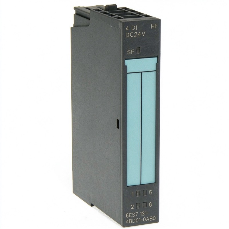
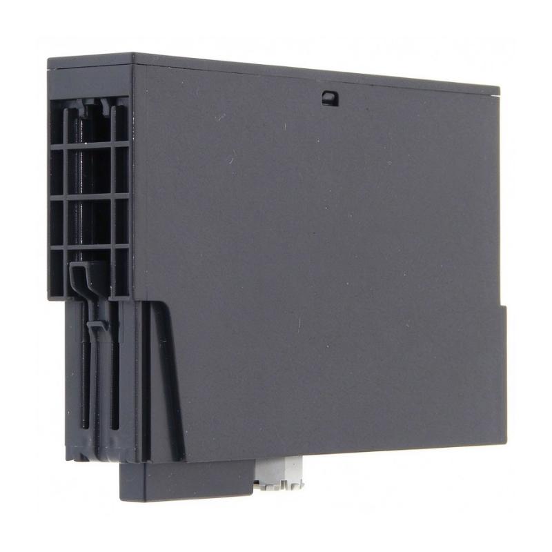
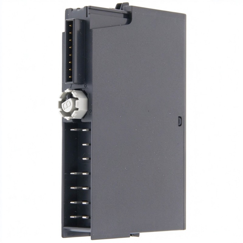
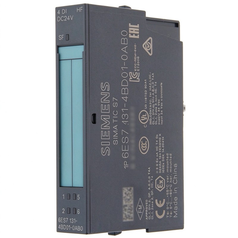
- Siemens
- 6ES7131-4BD01-0AB0
- Digital Input Electronic Module
- Germany
- 15 × 81 × 52 mm
- 0.177 kg
- Xiamen, China
- New & In Stock
- T/T, PayPal, Western Union
- 1 Year
- 1-3 Working Days
- DHL, UPS, TNT, FedEx and EMS.
- 24-Hour Service
- COO
- 5
Our advantage

Global Logistics
We have a 10-year logistics and express cooperation agreement, so our products can be shipped to any place in the world.

Brand new and original
Our products are imported in bulk from the place of origin. Because of the cooperative relationship, our products are all original and 100% new.

24-hour service
We provide 7*24 hours service to our customers. We will be there whenever you need us.

Price advantage
All our products are priced very favorably because we have our own warehouse and supply.
| Company Information | |||
| [email protected] | |||
| Mobile | +8615980777398 | ||
| +8615980777398 | |||
| 15980777398 |
Product Overview
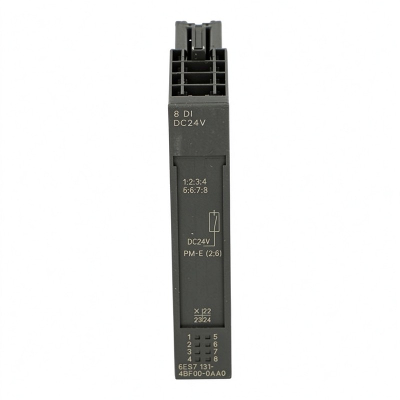
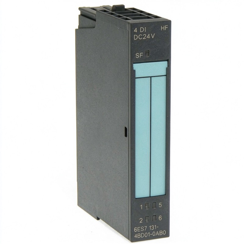
The Siemens 6ES7131-4BD01-0AB0 is a four-channel High Feature digital input electronic module for the SIMATIC ET 200S distributed I/O system. Designated 4DI DC24V HF, it accepts 24 V DC switching signals from field devices and adds configurable input delays and diagnostic capabilities to conventional digital signal acquisition.
In a machine automation system, several sensors may need to report their states to the controller while maintenance personnel also need a way to identify electrical faults. For example, a packaging machine may use proximity sensors to detect product positions, confirm actuator travel, and monitor the movement of a transfer mechanism. The 6ES7131-4BD01-0AB0 collects these signals through four input channels and supports additional monitoring of specified sensor-supply short-circuit conditions.
One of the module’s practical advantages is its configurable input response. The input delay can be selected from 0.1 ms, 0.5 ms, 3 ms, and 15 ms, allowing the signal-processing behavior to be matched to the connected sensor and machine cycle. A short delay can be appropriate for faster switching events, while a longer delay may help suppress unwanted transitions caused by electrical interference or sensor chatter. The correct setting depends on the signal duration and the response time required by the application.
The module also provides individual green input-status LEDs and a red SF group-fault indicator. These indicators help technicians distinguish normal channel activity from reported module faults during commissioning and troubleshooting. Its diagnostic functions are particularly useful when the control system must monitor both the state of a field signal and specified electrical problems in the sensor circuit.
As part of the ET 200S platform, the module operates through a compatible terminal module and the station’s backplane bus. It is suitable for distributed I/O installations where field signals are collected close to the equipment rather than individually routed to a central control cabinet.
Technical Specifications
| Parameter | Specification |
|---|---|
| Manufacturer | Siemens |
| Model | 6ES7131-4BD01-0AB0 |
| Product Family | SIMATIC ET 200S |
| Product Type | Digital Input Electronic Module |
| Module Designation | 4DI DC24V HF |
| Number of Digital Inputs | 4 |
| Rated Input Voltage | 24 V DC |
| Permissible Supply Voltage | 20.4–28.8 V DC |
| Signal Level for Logic 0 | -30 to +5 V DC |
| Signal Level for Logic 1 | +11 to +30 V DC |
| Typical Input Current | 8 mA at signal 1 |
| Configurable Input Delay | 0.1 / 0.5 / 3 / 15 ms |
| Input Characteristic | IEC 61131, Type 1 |
| Diagnostic Function | Encoder short-circuit diagnostics |
| Diagnostic Indicator | Red SF group-fault LED |
| Channel Status Indicators | Green LED per input |
| Hardware Interrupts | Supported, parameterizable |
| Isochronous Operation | Supported in compatible configurations |
| Two-Wire Sensor Compatibility | Supported, subject to specified leakage-current limits |
| Maximum Two-Wire Sensor Leakage Current | 1.5 mA |
| Encoder Supply Output Current | Up to 500 mA |
| Encoder Supply Protection | Electronic short-circuit protection |
| Backplane Bus Current Consumption | 10 mA maximum at 3.3 V DC |
| Typical Power Dissipation | 0.7 W |
| Potential Isolation | Inputs isolated from the backplane bus; channels are not isolated from each other |
| Maximum Cable Length, Unshielded | 600 m |
| Maximum Cable Length, Shielded | 1,000 m |
| Dimensions | 15 × 81 × 52 mm |
| Weight | 0.177 kg |
Product Features
- Four 24 V DC digital inputs: Collects four independent switching signals from compatible industrial sensors and switches.
- High Feature signal processing: Adds configurable input delays and diagnostic functions to standard digital input acquisition.
- Four selectable input delays: Offers 0.1 ms, 0.5 ms, 3 ms, and 15 ms settings for different signal-response requirements.
- Encoder short-circuit diagnostics: Detects specified short-circuit conditions in the sensor circuit and supports fault reporting.
- Red SF group-fault indicator: Provides a visual indication when a reportable group fault is present.
- Individual green channel LEDs: Helps technicians check the switching state of each input during commissioning.
- Electronic sensor-supply protection: Protects the encoder supply against specified short-circuit conditions.
- Hardware interrupt support: Allows configured input events to trigger interrupt processing in a compatible controller.
- ET 200S distributed I/O integration: Fits into a modular station for local field-signal acquisition.
- Support for synchronized applications: Can be used in compatible isochronous I/O configurations.
Working Principle
The 6ES7131-4BD01-0AB0 converts discrete electrical signals from field devices into input states that can be processed by the PLC. Its High Feature functions add configurable timing and diagnostic capabilities, but the actual machine response remains dependent on the controller program and system configuration.
A typical signal path is:
Field Sensors → 6ES7131-4BD01-0AB0 → ET 200S Backplane Bus → Interface Module → PLC
When a connected sensor switches, the module evaluates the input voltage against its specified logic thresholds. A voltage between +11 V and +30 V DC represents logic 1, while a voltage between -30 V and +5 V DC represents logic 0. The selected input delay determines the filtering interval applied to the transition before the input state is recognized.
Consider a conveyor system where sensors detect an approaching workpiece, confirm its position at a processing station, and verify that a pneumatic stopper has returned to its initial position. These signals can be assigned to separate input channels. The PLC uses the resulting states to determine whether the next step in the production sequence can proceed.
The configurable delay is useful when sensor signals contain brief unwanted transitions. A longer delay can reduce the effect of such switching fluctuations, but it also delays recognition of a genuine signal change. For fast-moving products or short detection windows, the selected setting must be checked against the minimum signal duration and required machine response.
The module’s diagnostic function monitors specified encoder short-circuit conditions. When a supported fault is detected, the module can report the condition through the ET 200S system, with the red SF LED providing a local visual indication. This helps narrow the troubleshooting process to the sensor-supply circuit or associated wiring.
Where hardware interrupts are configured, selected input events can initiate interrupt processing in the controller. This is useful when event handling needs to be coordinated with the application rather than relying exclusively on ordinary cyclic input updates. The interrupt configuration and PLC program must both support the intended behavior.
Role in a SIMATIC ET 200S Distributed I/O Architecture
The 6ES7131-4BD01-0AB0 serves as a local signal acquisition and diagnostic point within the ET 200S station. It collects four field inputs, processes their switching states, and communicates the resulting data through the backplane bus to the interface module and controller.
Field Devices → 4DI DC24V HF Module → ET 200S Backplane Bus → Interface Module → PLC
| System Element | Function |
|---|---|
| 6ES7131-4BD01-0AB0 | Acquires four 24 V DC digital signals and supports configurable delays and diagnostics |
| Compatible ET 200S Terminal Module | Provides the electrical connection and mounting interface |
| ET 200S Backplane Bus | Transfers I/O data within the station |
| ET 200S Interface Module | Connects the distributed I/O station to the control network |
| SIMATIC PLC | Processes input states, interrupts, and machine logic |
| 24 V DC Power Supply | Supplies compatible field sensors and associated control circuits |
| Proximity Sensors | Detect component presence, position, or movement |
| Limit Switches | Report mechanical end positions and operating states |
| Sensor Supply Circuit | Powers connected sensors within the specified electrical limits |
The High Feature variant is particularly relevant when the application requires configurable input timing or sensor-supply fault reporting. The selected terminal module, interface module, and PLC configuration must support the intended station arrangement and operating functions.
Industrial Applications
| Application | Typical Use |
|---|---|
| Packaging Machinery | Monitoring product detection, actuator positions, and machine-cycle signals |
| Conveyor Systems | Detecting workpiece arrival and confirming transfer positions |
| Automated Assembly Lines | Checking component presence and fixture positions |
| Material Handling Systems | Collecting signals from stops, guides, and transfer mechanisms |
| Pneumatic Automation | Monitoring cylinder end positions and valve-related mechanical states |
| Machine Tools | Reading discrete position signals and equipment interlocks |
| Inspection Stations | Acquiring part-present and fixture-position signals |
| High-Speed Production Cells | Selecting appropriate input delays for short-duration sensor signals |
| Distributed Control Cabinets | Collecting local sensor signals through an ET 200S station |
| Synchronized Automation Systems | Using compatible isochronous I/O configurations where required |
Installation and Maintenance
- Verify the complete article number: Confirm 6ES7131-4BD01-0AB0 and its 4DI DC24V HF designation. The standard and High Feature versions differ in their supported functions.
- Check terminal-module compatibility: Ensure that the electronic module is installed with a compatible ET 200S terminal module and that the station arrangement matches the system configuration.
- Confirm the 24 V DC supply: Check the field supply voltage and polarity before connecting sensors or commissioning the module.
- Verify sensor electrical characteristics: Review the sensor output type, operating voltage, current consumption, and off-state leakage current. Two-wire sensors must remain within the specified leakage-current limit.
- Configure the input delay: Select 0.1 ms, 0.5 ms, 3 ms, or 15 ms according to the sensor behavior and required response time. Confirm the setting through functional testing.
- Review diagnostic parameters: Check that encoder short-circuit diagnostics are configured appropriately for the connected sensor arrangement and required fault-monitoring behavior.
- Inspect the sensor-supply wiring: Check the supply conductors, reference connections, terminal contacts, and connected sensors for loose wiring or insulation damage.
- Confirm channel assignments: Match each field device to the intended input channel and verify that the PLC program uses the correct input address.
- Observe the status indicators: Compare the green channel LEDs with the actual sensor states. If the SF indicator is active, examine the available diagnostic information.
- Test configured interrupts: Where hardware interrupts are used, confirm that the selected events are recognized and handled correctly by the controller program.
- Investigate recurring faults systematically: Check sensor wiring, the encoder supply, terminal connections, and diagnostic settings before deciding that the module requires replacement.
- Document commissioning settings: Record the input-delay values, channel assignments, diagnostic configuration, interrupt settings, and any changes made during maintenance.
Compatible System Components
| Component | Function |
|---|---|
| Siemens SIMATIC ET 200S Terminal Module | Provides the mounting and electrical connection interface |
| Siemens ET 200S Interface Module | Connects the distributed I/O station to the control network |
| Siemens SIMATIC S7 PLC | Processes digital input data and executes machine logic |
| 24 V DC Power Supply | Supplies compatible field sensors and control circuits |
| Compatible Two-Wire Proximity Sensor | Provides a discrete signal within the module’s electrical limits |
| Three-Wire Proximity Sensor | Detects workpiece presence or position |
| Limit Switch | Reports mechanical end-of-travel or position status |
| Sensor Supply Wiring | Carries power to connected field devices |
| ET 200S Backplane Bus | Transfers input data between the electronic module and interface module |
Recommended Related Models
| Model / Product Family | Product Type | Typical Application |
|---|---|---|
| Siemens 6ES7131-4BD01-0AA0 | SIMATIC ET 200S Digital Input Electronic Module, 4DI DC24V ST | Four-channel standard digital input acquisition |
| Siemens 6ES7131-4BB01-0AB0 | SIMATIC ET 200S Digital Input Electronic Module, 2DI DC24V HF | Two-channel applications requiring configurable input delays and diagnostics |
| Siemens 6ES7131-4BD00-0AB0 | SIMATIC ET 200S Digital Input Electronic Module, 4DI DC24V HF | Four-channel High Feature input applications; verify the exact hardware configuration |
| Siemens 6ES7132 Series | SIMATIC ET 200S Digital Output Electronic Modules | Switching compatible actuators and discrete output loads |
| Siemens SIMATIC ET 200S | Distributed I/O System | Modular field-level signal acquisition and control |
Key Advantages
- Four 24 V DC input channels for collecting multiple field signals.
- Configurable input delays for different sensor and machine timing requirements.
- Encoder short-circuit diagnostics with a red SF group-fault indicator.
- Individual green LEDs for checking input states during commissioning.
- Electronic short-circuit protection for the encoder supply.
- Parameterizable hardware interrupt support in compatible control configurations.
Technical FAQs
What is the main difference between the 6ES7131-4BD01-0AB0 and the 6ES7131-4BD01-0AA0?
The 6ES7131-4BD01-0AB0 is the High Feature version. It adds configurable input delays, encoder short-circuit diagnostics, an SF group-fault indicator, and parameterizable hardware interrupts. The 6ES7131-4BD01-0AA0 is the standard four-channel 24 V DC input version and does not offer the same High Feature functionality.
How should the input delay be selected for a fast-moving workpiece?
The delay should be selected according to the sensor’s switching behavior, the duration of the detected signal, and the machine’s response requirements. The available settings are 0.1 ms, 0.5 ms, 3 ms, and 15 ms. A short delay supports faster recognition, while a longer delay may suppress unwanted transitions. The final setting should be verified under actual operating conditions.
What should be checked when the red SF LED indicates a fault?
Check the diagnostic information available through the ET 200S system and inspect the relevant sensor-supply circuit, field wiring, and connected devices. The module supports encoder short-circuit diagnostics, but the specific fault location must be established from the reported diagnostic information and electrical checks.
Can this module be used with two-wire proximity sensors?
Yes, compatible two-wire sensors can be connected, provided their electrical characteristics meet the module’s specifications. In particular, verify the maximum permissible off-state leakage current of 1.5 mA and ensure that the sensor’s active-state voltage meets the required logic-1 threshold.