

ProductPRODUCT
Featured products



Contact Us
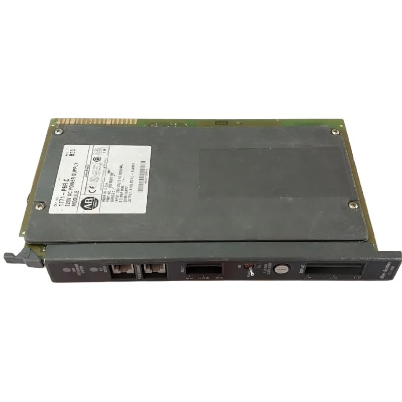
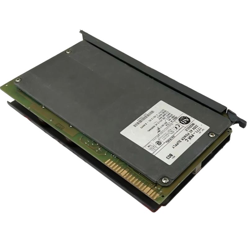
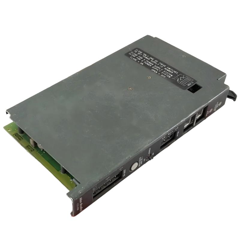
- Allen Bradley
- 1771-P4R
- Redundant Power Supply Module
- USA
- 27.9 × 2.5 × 17.8 cm
- 0.9kg
- Xiamen, China
- New & In Stock
- T/T, PayPal, Western Union
- 1 Year
- 1-3 Working Days
- DHL, UPS, TNT, FedEx and EMS.
- 24-Hour Service
- COO
- 5
Our advantage

Global Logistics
We have a 10-year logistics and express cooperation agreement, so our products can be shipped to any place in the world.

Brand new and original
Our products are imported in bulk from the place of origin. Because of the cooperative relationship, our products are all original and 100% new.

24-hour service
We provide 7*24 hours service to our customers. We will be there whenever you need us.

Price advantage
All our products are priced very favorably because we have our own warehouse and supply.
| Company Information | |||
| [email protected] | |||
| Mobile | +8615980777398 | ||
| +8615980777398 | |||
| 15980777398 |
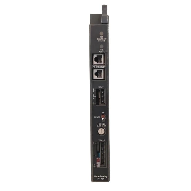
Allen-Bradley 1771-P4R Redundant Power Supply — Technical Specifications, Product Introduction, Applications, Advantages, and Related Models
1. Product Introduction
The Allen-Bradley 1771-P4R is a redundant power supply module designed for compatible PLC-5 and 1771 I/O control systems. It converts incoming AC power into the regulated 5 V DC supply required by the chassis backplane, helping power the installed control modules.
The defining feature of the 1771-P4R is its role in a redundant power supply arrangement. When multiple compatible power supplies are installed and connected according to the supported configuration, the system can continue supplying power when one unit fails, provided the remaining supplies have sufficient capacity for the connected load.
This module is intended for legacy industrial automation installations where PLC-5 processors and 1771 I/O modules remain in service. It is particularly relevant to maintenance teams that need to preserve an existing control architecture while reducing the risk of downtime caused by a power supply fault.
The 1771-P4R is a discontinued product. When sourcing a replacement, confirm the exact model, condition, wiring blocks, redundancy cable, and compatibility with the existing chassis and power arrangement.
2. Technical Specifications
| Parameter | Specification |
|---|---|
| Model | 1771-P4R |
| Brand | Allen-Bradley |
| Product name | Redundant Power Supply Module |
| Product series | PLC-5 / 1771 I/O |
| Module type | AC-input redundant power supply |
| Nominal input voltage | 120 V AC |
| Input voltage range | 97–132 V AC RMS |
| Input frequency | 47–63 Hz |
| Output voltage | 5 V DC |
| Maximum backplane output current | 8 A |
| Output power at rated voltage/current | Up to 40 W at 5 V DC and 8 A |
| Fuse | 1.5 A, 250 V, slow-blow |
| Maximum system output current with N+1 redundancy | 8 A with 2 units; 14 A with 3 units; 20 A with 4 units |
| Alarm relay rating | Up to 250 V AC; verify the applicable contact and load ratings |
| Maximum power dissipation | Approximately 16 W |
| Thermal dissipation | Approximately 47.8 BTU/h |
| Installation | One slot in a compatible 1771 I/O chassis |
| AC power wiring block | 941274-05; compatible terminal-block configuration must be verified |
| Relay wiring block | 941274-03; compatible terminal-block configuration must be verified |
| Redundancy connection | Dedicated redundancy cable for the supported arrangement |
| Operating temperature | 0°C to 60°C |
| Storage temperature | −40°C to 85°C |
| Relative humidity | 5–95%, non-condensing |
| Dimensions (W × H × D) | Approximately 27.9 × 2.5 × 17.8 cm |
| Weight (kg) | Approximately 0.9 kg |
| Product lifecycle | Discontinued |
The 1771-P4R is designed for a specific 1771 power architecture. Its output voltage and current ratings should not be interpreted as universal compatibility with every 1771 chassis or every power supply model in the family.
3. Main Functions and Operating Principle
3.1 AC-to-DC Power Conversion
The 1771-P4R accepts AC input within its specified voltage range and supplies regulated 5 V DC power to the compatible chassis backplane.
This backplane power is used by the installed PLC-5-related modules and other compatible 1771 I/O components. A stable supply is essential because voltage interruptions or inadequate current capacity can affect controller operation, I/O communication, and process control.
3.2 Redundant Power Supply Operation
The 1771-P4R is designed to be used in a supported redundant power supply configuration. In a redundant arrangement, multiple supplies are connected according to the required installation method so that the system can continue to provide power if one supply becomes unavailable.
Redundancy does not mean that every combination of power supplies is automatically compatible. The number of supplies, total load, redundancy cabling, chassis arrangement, and specified current limits must all be considered.
3.3 N+1 Power Capacity
N+1 redundancy means that the system has one additional power supply beyond the number needed to support the required load. If one supply fails, the remaining supplies are intended to maintain the required output, provided the installation is within its rated limits.
The 1771-P4R supports the following stated maximum system output-current arrangements:
| Redundant supply arrangement | Maximum system output current |
|---|---|
| 2 power supplies | 8 A |
| 3 power supplies | 14 A |
| 4 power supplies | 20 A |
These values are configuration-dependent. The current available to the actual system must be checked against the installed hardware, load distribution, and the applicable installation requirements.
3.4 Power-Fault Monitoring and Alarm Relay
The module includes an alarm relay function intended to provide a way to monitor power-supply status. In a compatible system, this status can be incorporated into a monitoring or alarm arrangement so that maintenance personnel can respond to a supply fault.
The alarm relay is rated for up to 250 V AC under the applicable conditions. The contact rating should not be interpreted as permission to switch any load at that voltage; the actual contact configuration and load characteristics must be verified.
3.5 Single-Slot Installation
The 1771-P4R occupies one slot in a compatible 1771 I/O chassis. This compact format allows it to be integrated into the existing modular system without requiring a separate standalone power supply enclosure.
The one-slot form factor does not eliminate the need to check chassis compatibility, wiring-block fit, clearance, and power distribution requirements.
4. Product Applications
4.1 PLC-5 Industrial Control Systems
The 1771-P4R is suitable for maintenance of compatible PLC-5 installations where the existing control system relies on 1771 I/O chassis power.
It may be used in production lines, machine-control panels, and established automation systems where replacing the entire controller architecture would require extensive engineering and commissioning work.
4.2 Manufacturing and Assembly Lines
Manufacturing systems often rely on a controller to coordinate conveyors, motors, actuators, sensors, and machine sequences. A power supply fault can interrupt the operation of several connected modules at once.
A properly designed redundant power arrangement using the 1771-P4R can help reduce the risk of a complete loss of backplane power following a single supply failure.
4.3 Packaging and Material Handling
Packaging machinery and material-handling systems may use PLC-5 controllers to coordinate product movement, sequencing, and machine interlocks.
In such installations, maintaining the existing power architecture can help avoid unnecessary changes to established equipment. The 1771-P4R may be useful where the original design specifically calls for this redundant power supply model.
4.4 Process Control and Continuous Production
Facilities with long-running production processes may use legacy PLC-5 systems for monitoring and control. In these environments, avoiding unexpected interruptions can be an important maintenance objective.
The 1771-P4R can form part of a redundant power design, but it does not by itself guarantee uninterrupted production. Controller redundancy, field power, communications, I/O wiring, and the process equipment must also be considered.
4.5 Utilities and Infrastructure Equipment
Some established pumping, distribution, and infrastructure control systems continue to operate legacy 1771 I/O equipment.
Where the original system uses a compatible redundant power arrangement, the 1771-P4R can be relevant as a maintenance spare. Suitability should be determined by the installed system requirements and the consequences of a power interruption.
4.6 Legacy Equipment Repair and Spare-Part Management
A common reason to purchase a 1771-P4R is to repair an existing installation without undertaking a major redesign.
For this purpose, it is important to source a unit with the correct model and revision, inspect its condition, and verify that the necessary wiring blocks and redundancy cable are available. A refurbished module should be tested before it is installed in a production system.
5. Product Advantages
5.1 Supports Improved Power Availability
The primary advantage of the 1771-P4R is its role in a compatible redundant power supply arrangement. With correctly sized and configured supplies, a single supply failure may not require the immediate shutdown of the complete control system.
The actual improvement in availability depends on the complete power arrangement and the remaining capacity after a fault.
5.2 Regulated 5 V DC Backplane Output
The module provides 5 V DC output for the compatible 1771 chassis backplane. This is the supply required by the applicable installed modules, making the power supply a fundamental part of the control system’s electrical infrastructure.
5.3 Compact One-Slot Design
The 1771-P4R occupies one chassis slot. This makes it possible to integrate the supply into a compatible modular system without the physical arrangement required by a separate standalone power unit.
5.4 Supports N+1 Redundancy Arrangements
The module can be used in supported multi-supply arrangements that provide additional power capacity. The specified current limits for two-, three-, and four-unit configurations help engineers assess whether a proposed arrangement is suitable for the required load.
5.5 Alarm Relay for Status Monitoring
The alarm relay provides a way to incorporate power-supply status into a compatible monitoring scheme. This can help maintenance personnel identify abnormal conditions and respond before a power issue causes a wider interruption.
5.6 Preserves Existing Control Infrastructure
For an existing PLC-5 system, replacing a failed supply with a compatible unit may be less disruptive than redesigning the entire control system. It can preserve existing wiring, chassis arrangements, and installed I/O hardware when the replacement is fully compatible.
5.7 Practical for Legacy Maintenance
Where the original equipment remains in service, maintaining a tested spare can shorten repair time and reduce the risk associated with long procurement lead times.
Because the 1771-P4R is discontinued, purchasing decisions should take account of the unit’s age, storage conditions, test results, and any available warranty or return terms.
6. Brand and Product Series
| Item | Description |
|---|---|
| Brand | Allen-Bradley |
| Product family | PLC-5 |
| I/O platform | 1771 I/O |
| Model | 1771-P4R |
| Product category | Redundant power supply |
| Input type | AC |
| Nominal input voltage | 120 V AC |
| DC output | 5 V DC |
| Maximum backplane current | 8 A per module |
| Installation format | One 1771 chassis slot |
| Main purpose | Supplying backplane power in a supported redundant configuration |
| Lifecycle status | Discontinued |
The 1771-P4R belongs to the power supply range associated with the PLC-5 and 1771 I/O architecture. Its function is different from that of a controller, communication module, digital input module, or output module.
When selecting a replacement, the input voltage, output rating, slot requirements, redundancy capability, and connection arrangement are more important than physical similarity alone.
7. Five Related Models
The following models are related through the 1771 power supply family. They differ in input voltage, power arrangement, or intended use, so they should not be treated as automatic substitutes for the 1771-P4R.
| Model | Product type | Key parameters | Dimensions (W × H × D) | Weight (kg) |
|---|---|---|---|---|
| 1771-P4 | 1771 power supply | 120 V AC input; 5 V DC output; 8 A rated backplane current; conventional supply configuration | One-slot/two-slot details depend on model version; verify drawing | Approx. 0.94 |
| 1771-P4S | 1771 power supply | 120 V AC nominal input; 97–132 V AC range; 5 V DC; up to 8 A; one-slot design | One chassis slot; verify physical drawing | Approx. 0.84 |
| 1771-P4S1 | 1771 power supply | 100 V AC nominal input; 85–120 V AC range; 5 V DC; up to 8 A | One chassis slot; verify physical drawing | Approx. 0.84 |
| 1771-P6R | Redundant power supply | 220 V AC nominal input; intended for a compatible redundant power configuration; verify exact output and system ratings | One chassis slot; verify physical drawing | Approx. 0.84–0.90 |
| 1771-P6S | 1771 power supply | 220 V AC nominal input; designed for the applicable 1771 power arrangement; confirm exact output characteristics | One chassis slot; verify physical drawing | Approx. 0.84–0.90 |
Important selection notes:
-
1771-P4 is related by its power supply function, but its redundancy characteristics and installation requirements must be checked before considering it as an alternative.
-
1771-P4S is a related 120 V AC supply, but a standard supply is not automatically equivalent to the redundant P4R arrangement.
-
1771-P4S1 has a different nominal input voltage and is only appropriate when the available supply voltage falls within its specified range.
-
1771-P6R is the most relevant model to investigate when the existing system uses a redundant supply architecture but has a different nominal AC input.
-
1771-P6S is part of the wider power supply family, but its precise role and ratings must be checked against the intended application.
Dimensions in this table are given as chassis-format descriptions where an exact mechanical drawing has not been confirmed. For cabinet design or shipping calculations, use the mechanical dimensions for the exact unit and revision rather than estimating from slot width alone.
8. Five Popular Allen-Bradley Models for Broader Automation Applications
The models below are examples of products from the broader Allen-Bradley automation portfolio. They serve different functions and are not direct replacements for the 1771-P4R.
| Model | Product series / type | Key parameters | Dimensions (W × H × D) | Weight (kg) |
|---|---|---|---|---|
| 1756-L83E | ControlLogix controller | Programmable controller for modular industrial control; supported capabilities depend on configuration and revision | Verify exact controller drawing | Verify exact unit |
| 1756-EN2T | ControlLogix EtherNet/IP communication module | Ethernet industrial communication module for compatible ControlLogix chassis | Verify exact module drawing | Verify exact unit |
| 1756-IB16 | ControlLogix digital input module | 16-point digital input module; confirm the exact voltage rating and revision | Verify exact module drawing | Verify exact unit |
| 1756-OB16E | ControlLogix digital output module | 16-point electronic output module; verify output voltage, current, and load requirements | Verify exact module drawing | Verify exact unit |
| 1756-A13 | ControlLogix chassis | 13-slot chassis for compatible ControlLogix modules | Verify exact chassis drawing | Verify exact unit |
These models represent a different control platform from the legacy 1771 system. If the goal is to modernize an installation that uses a 1771-P4R, the migration plan should cover controller compatibility, I/O replacement, power distribution, field wiring, communications, application logic, and commissioning.
A newer controller or I/O module does not directly replace the power conversion and redundancy function of the 1771-P4R. Power supply sizing and redundancy must be designed for the destination platform.
9. Installation and Compatibility Considerations
9.1 Confirm the Input Voltage
The 1771-P4R is designed for a nominal 120 V AC input, with an input range of 97–132 V AC RMS. Confirm the actual supply voltage and frequency before connecting the unit.
Do not substitute a 220 V AC supply model simply because it belongs to the same product family. Input-voltage compatibility is essential to safe and reliable operation.
9.2 Check the Chassis and Slot
Confirm that the existing 1771 chassis supports the module and that the correct slot and power arrangement are used.
A supply that physically fits may still be unsuitable if the chassis, backplane, wiring, or redundancy configuration differs from the intended design.
9.3 Verify the Redundancy Arrangement
The 1771-P4R should be used with the required compatible redundancy connections and a properly sized set of supplies.
Check the number of installed supplies, total current demand, redundancy cable, and the specified maximum current for the arrangement. Do not assume that adding more supplies automatically increases usable current without limit.
9.4 Inspect Wiring Blocks and Connections
Confirm the correct AC input and relay wiring blocks are available and suitable for the installed unit. Inspect terminals for damage, corrosion, loose connections, and signs of overheating.
All wiring work should be performed with the system isolated and according to the applicable electrical safety procedures.
9.5 Check the Total Backplane Load
Calculate the current demand of all installed modules and compare it with the capacity available in the selected redundancy configuration.
Allow for the specified operating conditions and any system-specific derating requirements. A supply arrangement that is adequate under normal operation must also be able to meet the required load following a supply failure.
9.6 Test Alarm and Fault Behavior
After installation, verify normal output voltage and check the alarm relay behavior according to the system’s intended monitoring design.
Where redundancy is required for operational reasons, the system should be tested under a controlled procedure to confirm that the remaining supply arrangement can support the required load.
10. Purchasing and Spare-Part Checklist
Before purchasing a 1771-P4R, confirm the following:
-
The full catalog number is 1771-P4R.
-
The nominal input voltage matches the installed AC supply.
-
The module’s output rating is suitable for the existing chassis load.
-
The intended redundant configuration is supported.
-
The required redundancy cable is included or available.
-
The correct AC and relay wiring blocks are present.
-
The housing, terminals, and electrical contacts are in acceptable condition.
-
The seller can provide meaningful test information for a used or refurbished unit.
-
The exact dimensions are checked if cabinet space or shipping requirements are important.
-
The weight is confirmed for the module itself, with accessories and packaging accounted for separately.
-
The replacement has been tested before being returned to production service.
11. Summary
The Allen-Bradley 1771-P4R Redundant Power Supply is a 120 V AC-input power supply designed to provide 5 V DC backplane power in compatible 1771 I/O systems. It supports a maximum output of 8 A per module and can be used in specified multi-supply arrangements to improve power availability.
Its main advantages are its one-slot installation format, regulated backplane output, support for redundant power configurations, alarm relay function, and suitability for maintaining established PLC-5 installations.
For a direct replacement, start by confirming the 1771-P4R’s input voltage, output requirements, redundancy arrangement, wiring connections, and hardware revision. Related models such as the 1771-P4S and 1771-P6R may be worth evaluating only when their electrical characteristics and intended operating arrangements match the application.
Because the 1771-P4R is discontinued, the condition and test status of any replacement unit deserve particular attention. Correct selection and validation are essential to preserving the reliability of the existing control system.