

ProductPRODUCT
Featured products
Contact Us
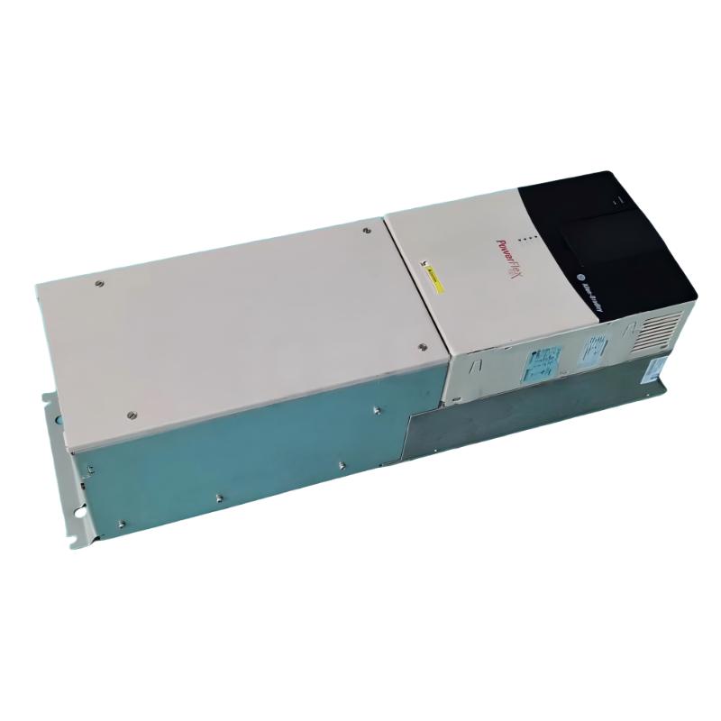
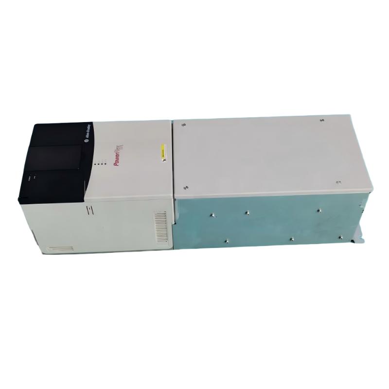
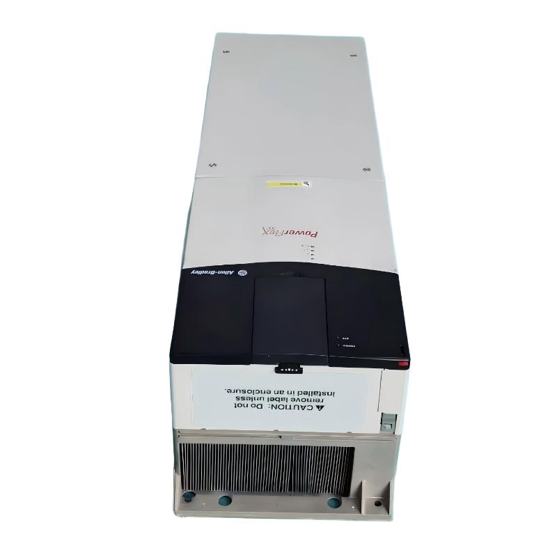
- Allen Bradley
- 20BP140A0ANNANC0
- PowerFlex AC Drive
- USA
- 689.6 × 308.9 × 275.4 mm
- 14.51kg
- Xiamen, China
- New & In Stock
- T/T, PayPal, Western Union
- 1 Year
- 1-3 Working Days
- DHL, UPS, TNT, FedEx and EMS.
- 24-Hour Service
- COO
- 2
Our advantage

Global Logistics
We have a 10-year logistics and express cooperation agreement, so our products can be shipped to any place in the world.

Brand new and original
Our products are imported in bulk from the place of origin. Because of the cooperative relationship, our products are all original and 100% new.

24-hour service
We provide 7*24 hours service to our customers. We will be there whenever you need us.

Price advantage
All our products are priced very favorably because we have our own warehouse and supply.
| Company Information | |||
| [email protected] | |||
| Mobile | +8615980777398 | ||
| +8615980777398 | |||
| 15980777398 |
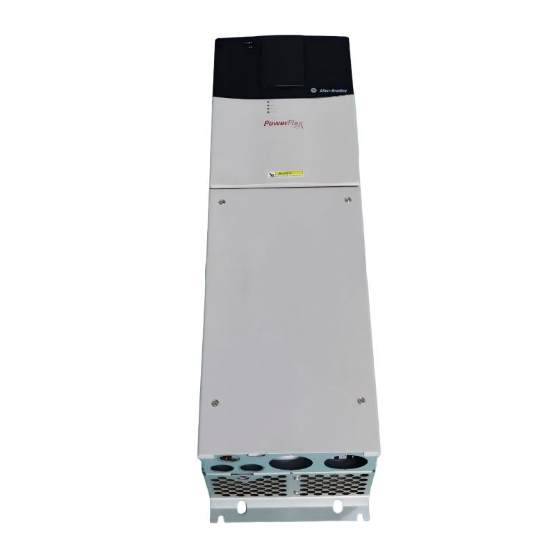
Allen-Bradley 20BP140A0ANNANC0 AC Drive: Technical Specifications, Product Description, Applications, Advantages, and Related Models
1. Product Overview
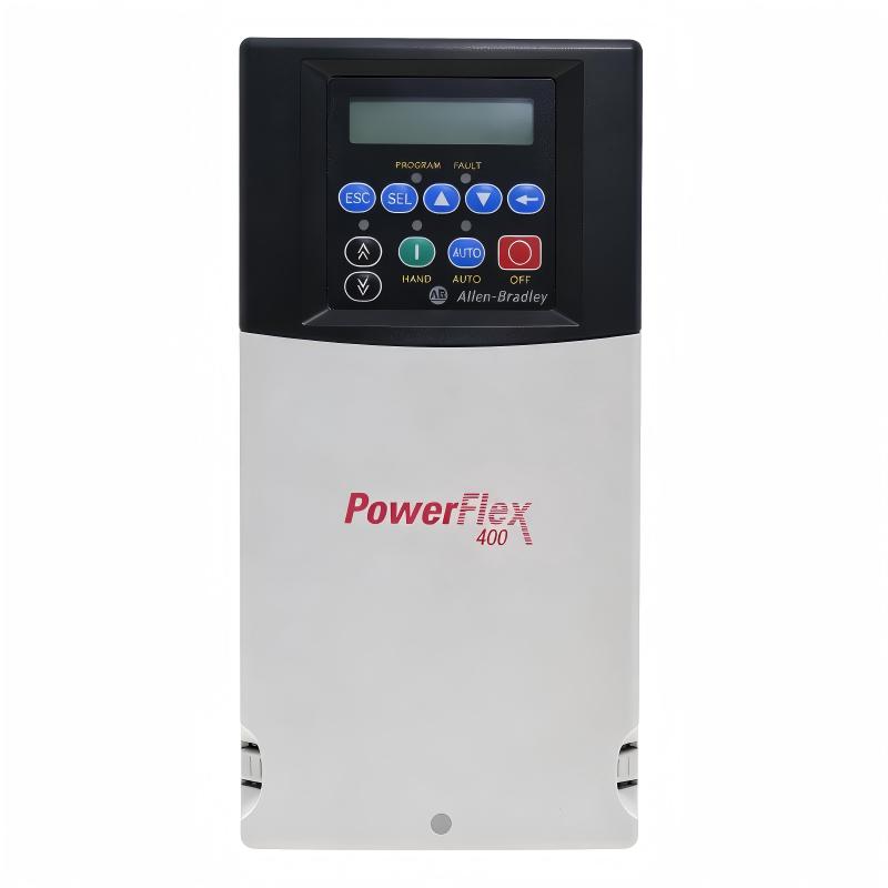
The Allen-Bradley 20BP140A0ANNANC0 is associated with the PowerFlex 700 family of industrial AC drives. This type of equipment is designed to regulate the speed and operation of AC motors in industrial machinery, manufacturing facilities, and automated production systems.
Variable-frequency drives allow motor speed to be adjusted according to process requirements. Rather than operating a motor continuously at a fixed speed, a drive can vary the electrical frequency and voltage supplied to the motor. When correctly selected and configured, this can improve process flexibility, provide controlled acceleration and deceleration, and reduce energy consumption in suitable applications.
The 20BP140A0ANNANC0 belongs to the 20B product family designation. Its 140 A rating designation suggests a higher-current drive configuration intended for industrial motor-control applications. The precise input voltage, output rating, duty classification, control options, dimensions, and weight should be confirmed against the individual unit’s nameplate and the mechanical documentation for the exact catalog number.
The complete catalog number is important because differences in the suffix can indicate variations in the factory configuration. Two drives with similar model numbers should not automatically be considered electrically or mechanically interchangeable.
2. Brand and Product Series
| Parameter | Description |
|---|---|
| Model | 20BP140A0ANNANC0 |
| Brand | Allen-Bradley |
| Product series | PowerFlex 700 |
| Product family | 20B |
| Product category | Industrial AC drive / variable-frequency drive |
| Primary function | AC motor speed and torque control |
| Typical installation | Industrial electrical control cabinet |
| Typical operating environment | Manufacturing plants, processing facilities, and industrial automation systems |
| Main purpose | Regulate motor operation according to process demand |
| Common system role | Motor-control component integrated with machinery and automation equipment |
| Rated-current class | 140 A designation; verify the actual nameplate rating |
| Dimensions | Must be confirmed for the exact configuration |
| Net weight | Must be confirmed for the exact configuration |
About the PowerFlex 700 Series
The PowerFlex 700 series is an industrial AC drive platform intended for a broad range of motor-control applications. It is used in systems where controlled speed, adjustable acceleration, and reliable operation are important to the production process.
The series is associated with applications involving conveyors, pumps, fans, mixers, material-handling equipment, and other industrial machinery. Depending on the drive configuration, the installation may use local control signals, an automation controller, communication options, or feedback devices to manage motor operation.
The suitability of a specific PowerFlex 700 model depends on the complete electrical rating and installed options. The series name alone does not establish the exact input voltage, motor power, braking arrangement, communication interface, or enclosure rating of the 20BP140A0ANNANC0.
3. Technical Specifications
The following table presents the product identification and principal engineering considerations. Exact configuration-dependent details are marked for verification rather than assigned unsupported numerical values.
| Parameter | Specification |
|---|---|
| Model | 20BP140A0ANNANC0 |
| Brand | Allen-Bradley |
| Series | PowerFlex 700 |
| Product family | 20B |
| Product type | Industrial AC drive |
| Rated output current | 140 A designation; confirm the nameplate value |
| Input voltage | Confirm from the unit nameplate |
| Input phase | Confirm from the exact catalog configuration |
| Output phase | Confirm from the applicable drive rating |
| Compatible motor type | Three-phase AC motor applications, subject to the exact drive rating |
| Motor power rating | Depends on voltage, current, duty classification, and load requirements |
| Output frequency | Depends on the drive’s supported operating range and configuration |
| Motor-control method | Confirm the supported control mode and installed options |
| Speed control | Adjustable motor-speed control |
| Torque control | Depends on the selected control mode and configuration |
| Overload capacity | Confirm the applicable normal-duty or heavy-duty rating |
| Acceleration settings | Configurable within the drive’s supported limits |
| Deceleration settings | Configurable within the drive’s supported limits |
| Analog inputs | Confirm against the exact hardware configuration |
| Analog outputs | Confirm against the exact hardware configuration |
| Digital inputs | Confirm against the exact hardware configuration |
| Digital outputs | Confirm against the exact hardware configuration |
| Communication interface | Depends on installed communication hardware or options |
| Encoder or feedback support | Confirm the required and installed feedback configuration |
| Dynamic braking | Confirm whether the required braking hardware is installed or must be added |
| Protective functions | Depends on drive hardware, parameter settings, and system design |
| Enclosure rating | Confirm from the product label and applicable documentation |
| Frame size | Confirm against the exact catalog number |
| Cooling method | Confirm from the applicable product documentation |
| Operating temperature | Subject to the specified rating, installation conditions, and derating requirements |
| Maximum installation altitude | Confirm the applicable rating and derating requirements |
| Dimensions (H × W × D) | Not verified for the exact model |
| Weight (kg) | Not verified for the exact model |
| Product condition | Depends on the individual unit’s condition and sales specification |
| Lifecycle status | Confirm current availability and support for this specific catalog number |
Understanding the 140 A Rating
The 140 A designation is an important starting point when evaluating this drive, but current alone is not sufficient to determine the correct motor power rating.
The usable motor rating depends on the drive’s voltage class, current rating, overload duty, ambient temperature, installation altitude, switching conditions, and driven-load characteristics. A motor that operates satisfactorily under a light or variable-torque load may impose different requirements under a high-starting-torque or constant-torque load.
For replacement applications, the drive should be matched to the motor’s nameplate current and the application’s overload requirements. A nominally similar current rating does not automatically guarantee equivalent performance.
4. Dimensions and Weight
Physical dimensions and weight are essential when planning a control cabinet, determining mounting requirements, arranging transportation, and estimating the handling equipment required for installation.
The exact dimensions and weight of the 20BP140A0ANNANC0 have not been verified here. They should be obtained from the dimensional drawing for the complete catalog number or measured and confirmed for the actual unit. Using values from another PowerFlex 700 model could lead to incorrect cabinet clearances or mounting arrangements.
| Mechanical parameter | Specification |
|---|---|
| Model | 20BP140A0ANNANC0 |
| Height (mm) | Not verified |
| Width (mm) | Not verified |
| Depth (mm) | Not verified |
| Overall dimensions (H × W × D) | Confirm using the exact mechanical drawing |
| Net weight (kg) | Not verified |
| Shipping weight (kg) | Depends on packaging and included accessories |
| Mounting arrangement | Confirm from the installation drawing |
| Required ventilation clearance | Follow the applicable installation requirements |
| Cable entry space | Depends on the cabinet layout and wiring arrangement |
| Cooling clearance | Must comply with the specified airflow requirements |
| Service access | Allow suitable access for inspection and maintenance |
When designing an installation, cabinet space should account for more than the drive’s external dimensions. Cable bending radius, terminal access, ventilation, heat dissipation, adjacent components, and maintenance access must also be considered.
For transportation planning, distinguish the drive’s net weight from its packed shipping weight. Packaging, accessories, and included hardware can increase the total shipment weight.
5. Product Description
The Allen-Bradley 20BP140A0ANNANC0 is intended for industrial motor-control systems where adjustable speed and coordinated operation are required. As a product associated with the PowerFlex 700 family, it fits the general category of AC drives used to manage motor speed in manufacturing and process equipment.
In a conventional fixed-speed installation, a motor generally runs according to the supply frequency and the characteristics of the connected load. A variable-frequency drive changes the electrical output supplied to the motor, allowing the operating speed to be adjusted to meet the requirements of the machine.
This capability can be valuable in systems where production conditions change throughout the day. A conveyor may require different speeds during loading and transfer. A pump may need to respond to changes in flow demand. A fan may require less speed during periods of lower ventilation demand.
By adjusting motor operation to the actual process, a drive can help improve operating flexibility and may reduce unnecessary mechanical or electrical stress. The benefits depend on correct sizing, parameter configuration, and the characteristics of the driven equipment.
The 20BP140A0ANNANC0 should be evaluated as part of a complete motor-control installation. Its performance depends not only on the drive itself but also on the motor, incoming power supply, wiring, grounding, cooling arrangement, control signals, and application settings.
6. Main Applications
6.1 Industrial Manufacturing
Manufacturing facilities use electric motors in production machinery, assembly lines, material-transfer systems, processing equipment, and auxiliary machines.
A variable-speed drive can allow motor operation to be adjusted according to production demand. It may also help coordinate machine sections that need to operate at different speeds during a production cycle.
Typical applications include:
-
Automated manufacturing lines.
-
Industrial processing machinery.
-
Packaging and material-transfer equipment.
-
Assembly and production systems.
-
Motor-driven auxiliary equipment.
-
General industrial machinery.
The drive must be selected according to the actual motor current, overload requirements, and operating profile of the machine.
6.2 Conveyor and Material-Handling Systems
Conveyors often operate under changing loads and production requirements. Variable-speed control allows the transport speed to be adjusted according to the movement of materials and the operating status of other equipment.
Controlled acceleration and deceleration can help reduce sudden mechanical changes when the application is designed for ramped operation. This can be useful in systems involving belts, rollers, gearboxes, and mechanical couplings.
Typical uses include:
-
Industrial belt conveyors.
-
Pallet transfer systems.
-
Production-line conveyors.
-
Warehouse material handling.
-
Automated sorting equipment.
-
Transfer mechanisms between processing stations.
Conveyor applications should be checked for starting torque, load inertia, stopping distance, and any requirement for external braking equipment.
6.3 Pumps and Fluid-Handling Equipment
Pumps are used in industrial water systems, cooling circuits, process-fluid transfer, and general fluid-handling applications.
Where the pump and process permit variable-speed operation, a drive can adjust motor speed to meet changing flow requirements. In appropriate systems, reducing pump speed may lower energy consumption compared with operating continuously at a higher speed and controlling flow through throttling alone.
Typical applications include:
-
Industrial circulation pumps.
-
Cooling-water systems.
-
Process-fluid transfer.
-
Water supply and distribution.
-
Utility pumping systems.
-
Industrial fluid-handling equipment.
Actual performance depends on the pump curve, system resistance, operating schedule, and control strategy. The installation should also provide appropriate protection against unsuitable flow, pressure, and dry-running conditions.
6.4 Fans and Blowers
Fans and blowers are used for ventilation, cooling, air circulation, and industrial process-air movement.
A drive can adjust fan speed to changing airflow requirements. In suitable systems, operating at a lower speed during periods of reduced demand may lower energy consumption.
Potential applications include:
-
Industrial ventilation.
-
Process-air handling.
-
Cooling fans.
-
Industrial blowers.
-
Air circulation systems.
-
Factory environmental-control equipment.
The selection should account for fan characteristics, motor current, the required operating range, and the cooling needs of the motor at lower speeds.
6.5 Mixers and Agitators
Mixers and agitators may need to operate at different speeds depending on the material being processed and the production stage.
Variable-speed operation can help the machine accommodate different mixing requirements and process conditions. It may also allow operators to refine acceleration and deceleration settings to suit the mechanical load.
Important selection factors include starting torque, load inertia, operating duration, motor cooling, and the frequency of speed changes.
6.6 Industrial Processing Machinery
Industrial processing equipment often requires a controlled operating speed to maintain consistent production conditions. Drives may be used in machinery involving continuous movement, mechanical processing, or other motor-driven operations.
The drive’s current rating and control capabilities should be matched to the load. Applications involving frequent starts, substantial load changes, or high torque at low speed may require additional evaluation.
6.7 Logistics and Production Support Systems
Industrial logistics systems use motors to move goods and materials between storage areas, processing stations, and production lines.
Adjustable speed can help coordinate movement, manage throughput, and adapt to different operating conditions. The precise benefit depends on the overall system design and the control functions available in the selected configuration.
7. Product Advantages
7.1 Flexible Speed Regulation
A key advantage of AC drive technology is the ability to adjust motor speed to match process requirements.
This is useful when machinery must operate at different speeds for different products, load conditions, or production stages. It can also reduce the need for certain mechanical speed-adjustment methods in applications suited to variable-speed control.
7.2 Better Coordination Between Machines
Production systems often contain several motors that must work together. Adjustable speed can help synchronize equipment and manage the transfer of products or materials between machine sections.
The final result depends on the application logic, available control interfaces, sensors, and any communication or feedback hardware used in the installation.
7.3 Potential Energy Savings
Variable-speed operation can reduce energy consumption in suitable applications, particularly some pump and fan systems.
The savings are not guaranteed. They depend on the load characteristics, operating schedule, system resistance, motor efficiency, and the difference between the original control method and the new operating strategy.
An energy assessment should compare actual operating conditions rather than assume that installing a drive automatically produces a particular percentage of savings.
7.4 Controlled Starting and Stopping
A drive can provide adjustable acceleration and deceleration settings. When properly configured, these can reduce abrupt changes in motor speed and may help limit mechanical shock.
The appropriate settings depend on load inertia, required cycle time, mechanical constraints, and stopping requirements. Applications requiring rapid or controlled stopping may need additional braking provisions.
7.5 Industrial Automation Compatibility
Industrial drives can form part of a wider automation system that includes programmable logic controllers, operator interfaces, sensors, and other control devices.
For this exact model, the available communication and I/O options must be confirmed. Network compatibility should not be inferred solely from the PowerFlex 700 series designation.
7.6 Support for Demanding Motor-Control Applications
A properly selected industrial drive can provide controlled motor operation under a defined set of operating conditions.
Reliable operation requires correct sizing, suitable cooling, appropriate protection, and adherence to installation and maintenance requirements. The drive’s nominal current rating should not be used as the only measure of suitability.
7.7 Adjustable Operating Parameters
Drive parameters commonly allow the installer to configure motor data, speed limits, acceleration and deceleration times, and control behavior within the capabilities of the hardware.
Correct configuration is essential. Incorrect motor data or inappropriate ramp settings can result in poor performance, nuisance trips, excessive current, or mechanical problems.
7.8 Potential Reduction in Mechanical Wear
Controlled acceleration and deceleration can reduce certain mechanical stresses associated with abrupt changes in speed. This may be beneficial for belts, couplings, gearboxes, and connected machinery.
The effect depends on the mechanical design and operating conditions. A drive cannot correct underlying mechanical problems such as misalignment, unsuitable components, or persistent overloading.
8. Installation and Engineering Considerations
Before installing or replacing the 20BP140A0ANNANC0, review the following requirements.
| Engineering item | Recommended verification |
|---|---|
| Model | 20BP140A0ANNANC0 |
| Input voltage | Match the drive to the actual power supply |
| Motor rated current | Verify against the motor nameplate and drive rating |
| Motor power | Confirm compatibility under the intended duty |
| Overload duty | Check the load’s starting and operating requirements |
| Load type | Identify variable-torque, constant-torque, or other load characteristics |
| Acceleration time | Set according to the machine’s inertia and operating cycle |
| Deceleration time | Check stopping requirements and braking limitations |
| Electrical protection | Select appropriate upstream protection |
| Grounding | Follow the applicable installation instructions |
| Wiring and shielding | Check cable type, routing, and electromagnetic compatibility requirements |
| Control interface | Verify required analog and digital signals |
| Communication | Confirm the installed network option and protocol |
| Feedback devices | Check whether encoder or other feedback hardware is required |
| Braking arrangement | Determine whether additional braking hardware is necessary |
| Enclosure | Confirm suitability for the installation environment |
| Cooling | Provide the specified ventilation and clearances |
| Ambient conditions | Review temperature, humidity, contamination, and altitude |
| Dimensions | Confirm from the exact mechanical drawing |
| Weight (kg) | Confirm the net weight of the specific unit |
| Parameter backup | Save existing settings before replacement |
| Lifecycle support | Confirm the availability of replacement equipment and service parts |
For replacement projects, document the original drive’s complete catalog number, motor nameplate information, control wiring, communication settings, and parameter configuration before beginning work.
Electrical isolation and maintenance must be performed by qualified personnel. Drives can contain hazardous stored electrical energy after incoming power has been disconnected, so the specified discharge period and safety procedure must be followed.
9. Five Related Models and Alternatives
The following shortlist is intended to support model comparison. It includes one closely related catalog-number variant and broader options within the same product family. The related catalog-number variant must not be assumed to have identical hardware or ratings without checking its complete configuration.
| Model | Product family | Main characteristics or selection purpose | Dimensions (H × W × D) | Weight (kg) |
|---|---|---|---|---|
| 20BP140A0ANNANC0 | PowerFlex 700 / 20B | Target model; confirm the exact current, voltage, options, and frame size | Not verified | Not verified |
| 20BP140A0ANNANC1 | Related PowerFlex 700 / 20B catalog-number variant | Compare the suffix and the complete hardware configuration before considering substitution | Not verified | Not verified |
| PowerFlex 700, 20B-series equivalent-current configuration | PowerFlex 700 | Consider when retaining a similar current class and drive platform is important | Depends on exact catalog number | Depends on exact catalog number |
| PowerFlex 700, 20B-series lower-current configuration | PowerFlex 700 | Consider only if the motor and load requirements allow a lower current rating | Depends on exact catalog number | Depends on exact catalog number |
| PowerFlex 700, 20B-series higher-current configuration | PowerFlex 700 | Consider when the application requires a higher current rating and the electrical system is compatible | Depends on exact catalog number | Depends on exact catalog number |
How to Select a Related Model
Confirm the complete catalog number. Differences in catalog suffixes can indicate changes in configuration, options, or other characteristics. Similar model numbers should not be treated as proof of interchangeability.
Compare the electrical ratings. The replacement must suit the input supply, motor current, operating duty, and load requirements.
Check the control configuration. Confirm whether the application requires specific communication hardware, feedback devices, I/O, or braking provisions.
Check mechanical compatibility. Compare the mounting arrangement, cabinet clearances, cooling requirements, dimensions, and net weight.
Review the replacement strategy. If an exact model is unavailable, consider a verified equivalent or a planned migration to another drive family. A newer model may require changes to wiring, control logic, mounting, and commissioning.
10. Five Other Allen-Bradley Drive Models for Comparison
The following models represent other industrial drive families that may be relevant when evaluating alternatives for a motor-control project. They cover different product categories and are not confirmed direct replacements for the 20BP140A0ANNANC0.
| Model | Series | Typical application focus | Key selection considerations | Dimensions (H × W × D) | Weight (kg) |
|---|---|---|---|---|---|
| 20G11ND077AA0NNNNN | PowerFlex 755 | Industrial variable-speed motor control | Confirm voltage, current, frame, options, and system compatibility | Not verified for exact configuration | Not verified |
| 20F11NC060JA0NNNNN | PowerFlex 700S | Industrial applications using the PowerFlex 700S platform | Verify the complete rating and required control functions | Not verified for exact configuration | Not verified |
| 25B-D017N104 | PowerFlex 525 | Compact, general-purpose drive applications | Compare motor current, voltage, overload requirements, and control options | Not verified for exact configuration | Not verified |
| 22B-D012N104 | PowerFlex 40 | General-purpose motor-speed control | Check whether the specific rating and features suit the application | Not verified for exact configuration | Not verified |
| 22F-D013N104 | PowerFlex 4M | Compact variable-speed applications | Confirm the exact electrical rating, installation requirements, and functions | Not verified for exact configuration | Not verified |
PowerFlex 755
The PowerFlex 755 family is associated with industrial motor-control applications requiring a range of drive ratings and options. It may be considered in modernization projects where the existing control architecture and motor requirements are reviewed in detail.
A migration from the 20B family to a PowerFlex 755 model should include an assessment of the power supply, motor data, control interfaces, communication requirements, physical dimensions, and commissioning work.
PowerFlex 700S
The PowerFlex 700S is a related industrial drive family with its own control and configuration characteristics. It may be relevant when evaluating specific industrial motor-control requirements, but compatibility must be established from the actual hardware and application specifications.
PowerFlex 525
The PowerFlex 525 is a compact drive family used in applications that fit its available ratings and functions. It may be suitable for smaller motors or different machinery, but its current rating and application capabilities must be compared carefully before it is considered as an alternative.
PowerFlex 40
The PowerFlex 40 is a general-purpose drive family intended for applications within its particular electrical and functional limits. It can be considered for suitable motor-control duties, but should not be treated as a replacement for a higher-current drive solely because both products are manufactured under the same brand.
PowerFlex 4M
The PowerFlex 4M is a compact drive family intended for applications that suit its ratings and capabilities. Its physical size, current rating, control features, and mounting requirements should be assessed against the actual machine.
11. Maintenance and Reliability
Long-term drive performance depends on correct installation, appropriate loading, suitable cooling, and regular inspection.
Recommended maintenance practices include:
-
Keep ventilation openings clear and maintain the specified cooling clearance.
-
Inspect the cabinet for dust, moisture, corrosion, and signs of overheating.
-
Check electrical connections in accordance with the approved maintenance procedure.
-
Inspect grounding, cable routing, and shielding where applicable.
-
Review fault history when recurring operating problems occur.
-
Keep a backup of parameter settings and relevant commissioning records.
-
Verify that replacement components match the exact drive configuration.
-
Follow the specified electrical isolation and stored-energy discharge procedures.
A drive that repeatedly trips should not automatically be replaced without investigating the cause. Problems may originate from an unsuitable load, motor faults, incorrect parameters, poor cooling, power-supply issues, wiring faults, or incompatible control signals.
Maintenance should be performed by qualified personnel using the applicable instructions for the installed drive.
12. Purchasing Recommendations
When sourcing the 20BP140A0ANNANC0, request confirmation of the complete catalog number and clear photographs of the product nameplate. This is particularly important for surplus, used, or refurbished equipment.
The following details should be checked before purchase:
| Purchasing item | What to confirm |
|---|---|
| Model | 20BP140A0ANNANC0 |
| Catalog number | Confirm every character of the part number |
| Electrical rating | Verify input voltage, output current, and duty classification |
| Configuration | Confirm included hardware and options |
| Physical dimensions | Obtain the exact dimensional drawing |
| Net weight (kg) | Confirm the actual unit specification |
| Product condition | Establish whether the unit is new, unused surplus, refurbished, or used |
| Accessories | Confirm which accessories and removable components are included |
| Documentation | Check the availability of applicable installation and configuration information |
| Warranty | Confirm the terms and coverage |
| Compatibility | Compare against the existing motor and control system |
| Replacement suitability | Check electrical, mechanical, and control-system requirements |
For replacement work, the original drive’s nameplate, motor nameplate, wiring diagram, parameter backup, and communication configuration should be reviewed together. This helps avoid ordering a drive that matches the general product family but differs in a critical electrical or control feature.
If an exact unit is unavailable, a related drive may be suitable after an engineering review. Any proposed alternative should be assessed for current rating, overload capability, motor-control requirements, enclosure, mounting, communication, and commissioning implications.
13. Overall Assessment
The Allen-Bradley 20BP140A0ANNANC0 is associated with the PowerFlex 700 industrial AC drive family and is relevant to applications requiring adjustable motor speed and coordinated industrial operation.
Its potential application areas include manufacturing machinery, conveyors, pumps, fans, mixers, material-handling systems, and other motor-driven equipment. The main benefits of drive technology include adjustable speed, controlled acceleration and deceleration, improved process flexibility, and possible energy savings in suitable installations.
For technical selection, the most important considerations are the exact voltage rating, output current, motor compatibility, overload duty, control options, enclosure requirements, cooling, and mechanical installation constraints.
Dimensions and weight: The exact height, width, depth, and net weight of the 20BP140A0ANNANC0 have not been verified in this description. The same applies to the comparison models. These figures should be confirmed from the mechanical documentation for the exact catalog number or from the physical unit before cabinet design, transport planning, or purchase.
The safest approach is to use the full catalog number and nameplate as the basis for identification, then confirm electrical ratings, hardware configuration, mechanical dimensions, and application compatibility before selecting or replacing the drive.