

ProductPRODUCT
Featured products
Contact Us
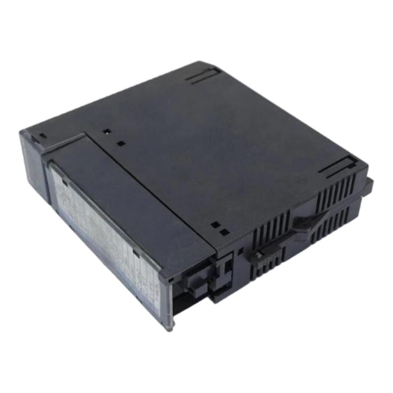
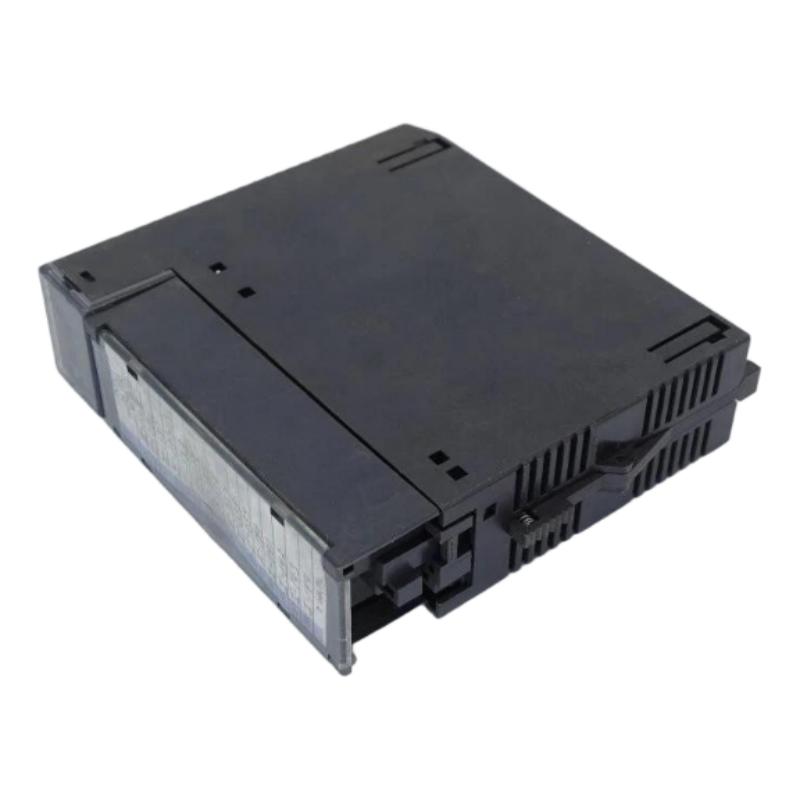
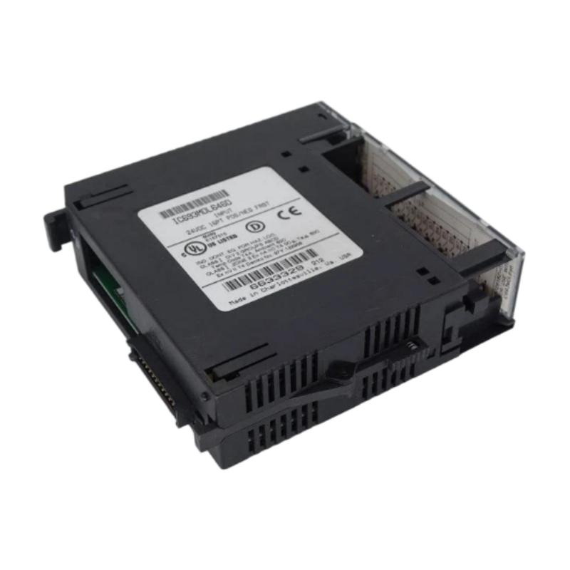

- GE
- IC693MDL646D
- Positive/Negative Logic Input Module
- USA
- 142 x 30 x 130 mm
- 0.42 kg
- Xiamen, China
- New & In Stock
- T/T, PayPal, Western Union
- 1 Year
- 1-3 Working Days
- DHL, UPS, TNT, FedEx and EMS.
- 24-Hour Service
- COO
- 5
Our advantage

Global Logistics
We have a 10-year logistics and express cooperation agreement, so our products can be shipped to any place in the world.

Brand new and original
Our products are imported in bulk from the place of origin. Because of the cooperative relationship, our products are all original and 100% new.

24-hour service
We provide 7*24 hours service to our customers. We will be there whenever you need us.

Price advantage
All our products are priced very favorably because we have our own warehouse and supply.
| Company Information | |||
| [email protected] | |||
| Mobile | +8615980777398 | ||
| +8615980777398 | |||
| 15980777398 |
Product Overview
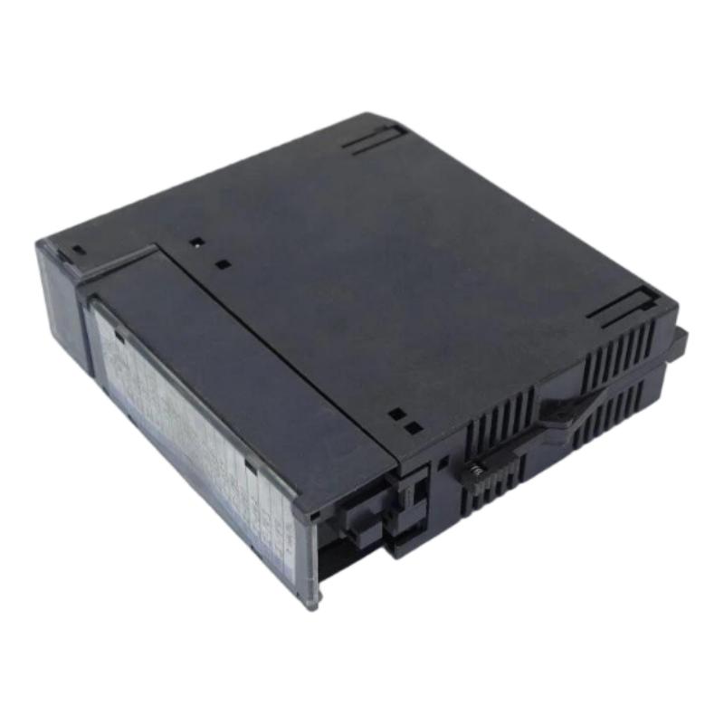
In industrial automation systems, reliable digital signal acquisition is essential for monitoring machine status, detecting field conditions, and executing programmed control sequences. The GE IC693MDL646D Positive/Negative Logic Input Module is associated with the GE Fanuc Series 90-30 Programmable Logic Controller (PLC) platform and is designed to receive digital signals from compatible industrial field devices.
Digital input modules serve as the interface between field-level electrical signals and the PLC control program. They allow the controller to recognize conditions such as push-button activation, limit switch operation, sensor detection, and equipment status changes. By converting electrical input conditions into readable PLC input states, these modules help automated systems respond to changes in the operating environment.
The IC693MDL646D belongs to the Series 90-30 digital input module family. Its positive/negative logic designation refers to the input circuit’s ability to accommodate the specified current-flow and field-wiring arrangements. The precise voltage range, channel configuration, and wiring requirements must be confirmed against the documentation applicable to the exact module revision.
For maintenance engineers and industrial spare-parts purchasers, the GE IC693MDL646D is relevant when maintaining compatible Series 90-30 PLC installations that require digital input functionality. Correct module identification and appropriate field wiring are important for reliable signal detection and stable PLC operation.
Technical Specifications
| Parameter | Details |
|---|---|
| Manufacturer | GE / GE Fanuc |
| Model | IC693MDL646D |
| Product Type | Positive/Negative Logic Input Module |
| Product Category | PLC Digital Input Module |
| Compatible PLC Platform | GE Fanuc Series 90-30, subject to configuration verification |
| Primary Function | Receives digital signals from compatible field devices |
| Input Logic | Positive/Negative Logic |
| Signal Type | Digital input |
| Input Voltage | Verify the rated voltage and supported input range for the exact module revision |
| Number of Input Points | Confirm against the applicable technical documentation |
| Input Current | Verify the specified input current and threshold characteristics |
| Input Response Time | Confirm from the applicable module specification |
| Isolation Characteristics | Verify the documented isolation arrangement |
| Dimensions | 142 × 30 × 130 mm |
| Weight | 0.42 kg |
| Installation | Compatible Series 90-30 PLC rack, subject to system requirements |
| Field Connections | According to the applicable module wiring diagram |
| Application | Industrial machine monitoring and digital signal acquisition |
| Typical Use | Receiving status and switching signals from compatible field devices |
Technical note: The dimensions of 142 × 30 × 130 mm and weight of 0.42 kg are based on the supplied product information. The exact input voltage, number of input points, current requirements, response time, and isolation characteristics have not been independently confirmed for the IC693MDL646D designation. These values should be checked against the module label and applicable technical documentation before installation or procurement.
Function and Working Principle
The GE IC693MDL646D Positive/Negative Logic Input Module provides digital signal acquisition for a compatible Series 90-30 PLC system. Its primary role is to receive electrical signals from external devices and make their corresponding states available to the PLC control program.
In a typical industrial automation application, sensors, switches, and other field devices detect changes in a machine or process. These devices generate electrical signals that represent conditions such as equipment running, a component reaching a limit, a guard being closed, or a process event occurring.
The digital input module processes compatible electrical input conditions according to its circuit design and presents the resulting input states to the PLC.
The main functions of the module include the following.
1. Digital Signal Acquisition
The module receives electrical signals from compatible field devices. The input circuitry determines whether the signal satisfies the applicable electrical thresholds and represents the corresponding logical state to the PLC.
2. Positive and Negative Logic Support
Positive and negative logic describe different relationships between electrical signal conditions, current flow, and the interpretation of an input state. A module designed for the specified positive/negative logic arrangements can support the field-wiring configurations permitted by its technical documentation.
The exact wiring method must be selected according to the module’s input circuit and the characteristics of the connected devices. The logic designation should not be interpreted as permission to connect arbitrary voltage levels or field devices.
3. Machine Status Monitoring
Digital input signals can represent equipment conditions such as motor auxiliary contacts, push-button states, limit switch positions, and sensor detection events. The PLC uses these states to determine the next action in its programmed sequence.
4. Control Sequence Execution
Once the PLC receives the input states, its control program can evaluate them and activate appropriate outputs. For example, a detected part may trigger the next step in a packaging sequence, provided all required operating conditions are satisfied.
5. Integration with Field Devices
The module creates a structured interface between field-level electrical signals and the PLC’s internal control logic. Correct wiring and compatible input characteristics are essential for preventing false signals, missed detections, and unexpected machine responses.
A digital input module does not independently control a motor or execute the complete machine sequence. It supplies input information to the PLC, which processes that information according to the programmed logic.
Role in Industrial Control Systems
The GE IC693MDL646D can function as part of the digital signal acquisition layer in a compatible Series 90-30 PLC installation. It enables the controller to monitor external equipment and respond to changing machine or process conditions.
A typical PLC architecture includes field sensors, input modules, a CPU, output modules, and the equipment controlled by those outputs. Each component has a specific responsibility within the overall automation system.
The IC693MDL646D may be used to receive signals from:
- Industrial proximity sensors with compatible electrical outputs
- Limit switches and position switches
- Push-buttons and selector switches
- Relay auxiliary contacts
- Equipment status contacts
- Compatible digital sensing devices
- Other field devices that meet the module’s specified input requirements
The suitability of any field device depends on its voltage, current, switching characteristics, wiring arrangement, and compatibility with the input circuit.
For example, an automated assembly machine may use a limit switch to detect whether a mechanical slide has reached a defined position. The input module receives the corresponding electrical signal and makes the input state available to the PLC. The controller then evaluates the programmed conditions and determines whether the next operation can proceed.
This arrangement helps the PLC coordinate equipment based on actual field conditions rather than relying solely on elapsed time or predetermined sequences.
Digital input modules can also be used to monitor equipment status during troubleshooting. When an expected input state is missing, maintenance personnel can investigate the field device, wiring, power supply, terminal connections, or module configuration.
Industrial Applications
The GE IC693MDL646D is relevant to industrial applications that require digital signal acquisition in compatible GE Fanuc Series 90-30 PLC systems.
Manufacturing Automation
Production lines use digital signals to detect product presence, confirm machine positions, and monitor equipment status. A suitable input module allows the PLC to use these signals when coordinating manufacturing sequences.
Machine Control Systems
Automated machinery frequently relies on switches and sensors to confirm that components have reached required positions. Digital inputs provide the PLC with information needed to execute programmed transitions and interlocks.
Packaging Equipment
Packaging machines use digital sensors to detect containers, products, guards, and mechanical positions. Input signals can help the PLC coordinate filling, sealing, labeling, and material-handling operations.
Conveyor and Material Handling Systems
Conveyor systems may use photoelectric sensors, proximity switches, and limit switches to detect objects and monitor movement. Compatible digital input hardware allows these signals to be incorporated into the control sequence.
Process Equipment Monitoring
Industrial process systems often use discrete status contacts to indicate equipment conditions, such as auxiliary relay states or local operating status. The PLC can use these signals for monitoring, sequencing, and fault handling.
Legacy PLC Maintenance
Facilities that continue operating Series 90-30 control systems may need to replace existing digital input modules while preserving established programs and field wiring. Correct identification of the original module is essential for maintaining compatibility.
For applications involving personnel protection or emergency shutdown functions, the input module should not be assumed to provide safety-rated functionality. Safety functions must use appropriately rated equipment and an engineered safety architecture.
Installation and System Integration
Correct installation is essential for reliable digital signal acquisition. Before installing or replacing the GE IC693MDL646D, engineers should confirm the module identification, input specifications, and compatibility with the target Series 90-30 PLC system.
1. Verify the Module Identification
Check the complete model designation, including the final letter D, and inspect the product label for revision information. Confirm that the selected module matches the component specified in the equipment documentation.
2. Confirm PLC Rack Compatibility
Verify the CPU, rack arrangement, available slot, and module installation requirements. The physical fit of a module alone does not establish compatibility with the complete PLC configuration.
3. Check Field Signal Characteristics
Confirm the voltage, current, switching behavior, and logic arrangement of the connected field devices. Ensure that these characteristics fall within the module’s specified input limits.
4. Prepare the Installation Environment
Follow the equipment’s electrical isolation and lockout procedures before handling the module. Use appropriate electrostatic-discharge precautions and inspect the rack and connectors for damage.
5. Connect the Field Wiring
Follow the correct terminal assignments and wiring diagrams. Select the appropriate positive or negative logic arrangement according to the module documentation and the connected field-device circuitry.
Do not infer terminal assignments from wire colors or from another module with a similar model number.
6. Verify Input Addressing
Confirm the module’s assigned input references and the way those references are used in the PLC program. Correct addressing is essential to ensure that the program evaluates the intended field signals.
7. Test the Input States
After installation, perform the required functional checks. Activate the relevant field devices and verify that the expected input states appear in the PLC monitoring or diagnostic environment.
8. Document the Installation
Record the module model, hardware revision, wiring arrangement, input assignments, and commissioning results. This information helps maintenance personnel diagnose future problems and order suitable replacement components.
The precise wiring diagram, terminal assignments, input ratings, and installation procedure depend on the exact module documentation. These details should be verified before connecting field wiring.
Compatible System Components
The GE IC693MDL646D operates as part of a broader PLC control architecture. Its integration depends on the correct combination of controller hardware, rack components, field devices, and output equipment.
| Component or Equipment | Function | Relationship to IC693MDL646D |
|---|---|---|
| GE Series 90-30 PLC CPU | Executes the control program and processes input states | Uses the input information supplied by the module |
| Series 90-30 Rack and Backplane | Houses compatible PLC modules and provides internal connections | Must satisfy the module’s installation requirements |
| PLC Power Supply | Supplies power to the PLC rack | Must meet the requirements of the installed PLC system |
| Digital Output Module | Provides discrete control signals to external devices | Works alongside input modules to support the complete control sequence |
| Analog Input Module | Acquires variable electrical signals from field instruments | Provides a different type of input functionality |
| Proximity Sensors | Detect the presence or position of objects | Can provide input signals when their electrical characteristics are compatible |
| Limit Switches | Detect mechanical position or travel limits | Provide discrete position information to the PLC |
| Push-Buttons and Selector Switches | Allow operators to provide discrete commands | Can supply input signals through suitable field wiring |
| Relay Auxiliary Contacts | Indicate the state of compatible electrical equipment | Can provide equipment-status information |
| Field Wiring and Terminal Connections | Carry signals from field devices to the PLC | Must follow the correct wiring diagram and electrical requirements |
These components represent common integration categories rather than a guaranteed bill of materials for every IC693MDL646D installation. Exact compatibility must be established from the installed PLC configuration and the module’s electrical specifications.
Recommended Alternative Models
When selecting a replacement for the GE IC693MDL646D, the original model should be the primary reference. If it is unavailable, the alternative must be evaluated according to input voltage, logic compatibility, number of input points, terminal arrangement, rack requirements, and hardware revision.
| Model | Type | Key Feature | Application |
|---|---|---|---|
| IC693MDL646D | Positive/Negative Logic Input Module | Original requested designation | Preferred identification for a like-for-like replacement |
| IC693MDL646 | Positive/Negative Logic Input Module family designation | Related base-model reference | Verify the revision and complete electrical specifications before ordering |
| IC693MDL645 | Digital Input Module | Related Series 90-30 digital input designation | Consider only after confirming input characteristics and compatibility |
| IC693MDL640 | Digital Input Module | Another Series 90-30 digital input product reference | Evaluate according to the required voltage, logic, and channel configuration |
| Compatible Series 90-30 Digital Input Module | PLC digital input hardware | Provides discrete signal acquisition | Select only when the module meets the original system’s electrical and mechanical requirements |
Important selection guidance: The IC693MDL646 and other related model numbers should not automatically be treated as interchangeable with the IC693MDL646D. Differences in hardware revision, input voltage, logic arrangement, channel configuration, or terminal requirements may affect compatibility.
Before purchasing an alternative, compare the original module’s complete designation with the proposed replacement’s specifications and the applicable Series 90-30 documentation. A module with a similar product name is not necessarily a direct replacement.
Key Advantages
The GE IC693MDL646D Positive/Negative Logic Input Module can provide several benefits when correctly integrated into a compatible Series 90-30 PLC system.
- Digital signal acquisition: Receives supported electrical signals from industrial field devices.
- Positive/negative logic support: Accommodates the specified logic and field-wiring arrangements documented for the module.
- Machine status monitoring: Allows the PLC to receive discrete information about equipment conditions and operating states.
- Control sequence integration: Provides input information that the PLC program can use to coordinate automated operations.
- Legacy system maintenance: Serves as a specific spare-part reference for compatible Series 90-30 installations.
- Flexible field-device integration: Can interface with suitable switches, sensors, and status contacts.
- Targeted troubleshooting: Helps maintenance teams identify the relevant digital input component when investigating signal-acquisition problems.
These benefits depend on correct module selection, suitable field devices, accurate wiring, and appropriate PLC program configuration.
Technical FAQs
1. What is the GE IC693MDL646D?
The GE IC693MDL646D is identified as a positive/negative logic input module associated with the GE Fanuc Series 90-30 PLC platform. It receives compatible digital signals from external field devices.
2. What are the dimensions and weight of the IC693MDL646D?
The supplied product information lists dimensions of 142 × 30 × 130 mm and a weight of 0.42 kg. These values should be checked against the physical unit when exact mounting or shipping requirements are important.
3. What does positive/negative logic mean?
Positive and negative logic describe different relationships between electrical signal conditions, current flow, and logical input states. The supported wiring arrangement must follow the module’s electrical specifications and wiring diagram.
4. What field devices can be connected to this module?
Potential devices include compatible proximity sensors, limit switches, push-buttons, selector switches, and relay auxiliary contacts. Each device must meet the module’s voltage, current, and input-circuit requirements.
5. Is the IC693MDL646D an analog input module?
No. It is a digital input module. It receives discrete electrical states rather than measuring a continuously varying analog signal.
6. Can the IC693MDL646 replace the IC693MDL646D?
That should not be assumed without verification. Compare the complete model designations, input specifications, revision information, and applicable system documentation before treating the base-model reference as an interchangeable replacement.
7. What should be checked before ordering?
Confirm the full model number, the final letter D, the product label, hardware revision, PLC CPU, rack configuration, input voltage, logic arrangement, and number of required input points.
8. What can cause a digital input signal to fail?
Potential causes include incorrect field wiring, a missing field-device supply, incompatible voltage levels, damaged sensors, loose terminals, incorrect PLC addressing, or a faulty input channel. Troubleshooting should follow the appropriate electrical safety and diagnostic procedures.
9. Can this module be used for emergency-stop circuits?
Do not assume that the module provides a safety-rated input function. Emergency-stop and other safety-critical functions require appropriately rated safety components and a validated safety design.
10. Is the IC693MDL646D suitable for new automation projects?
It may be considered for projects that retain compatible Series 90-30 equipment. For new systems, engineers should evaluate lifecycle support, spare-parts availability, integration requirements, and long-term maintenance needs.
Conclusion
The GE IC693MDL646D Positive/Negative Logic Input Module is a digital signal acquisition component associated with the GE Fanuc Series 90-30 PLC platform. It enables a compatible controller to receive discrete signals from field devices and use those signals in programmed machine-control and process-monitoring operations.
The supplied product dimensions are 142 × 30 × 130 mm, and the supplied weight is 0.42 kg. Before purchasing or installing a replacement, engineers should verify the complete model designation, hardware revision, input voltage, logic arrangement, channel configuration, and rack compatibility.
For industrial maintenance teams, system integrators, and spare-parts suppliers, accurate identification and careful verification of electrical compatibility help reduce purchasing errors and support reliable operation of existing industrial automation systems.