

ProductPRODUCT
Featured products
Contact Us
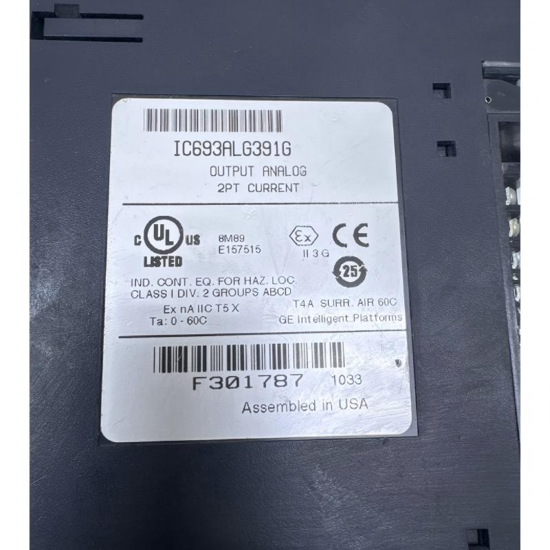
- GE
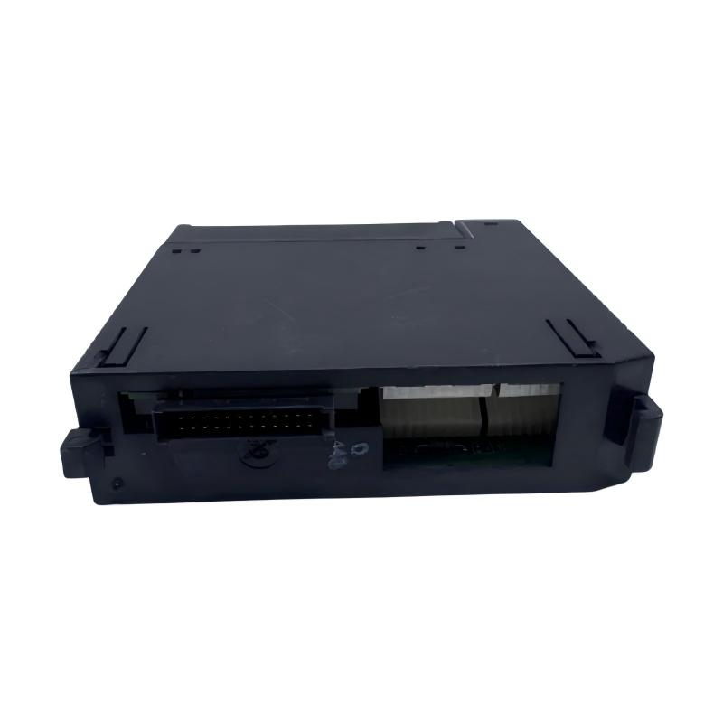
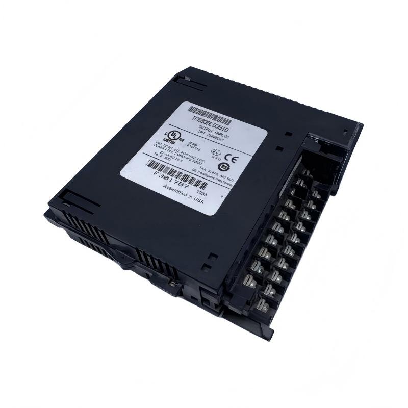
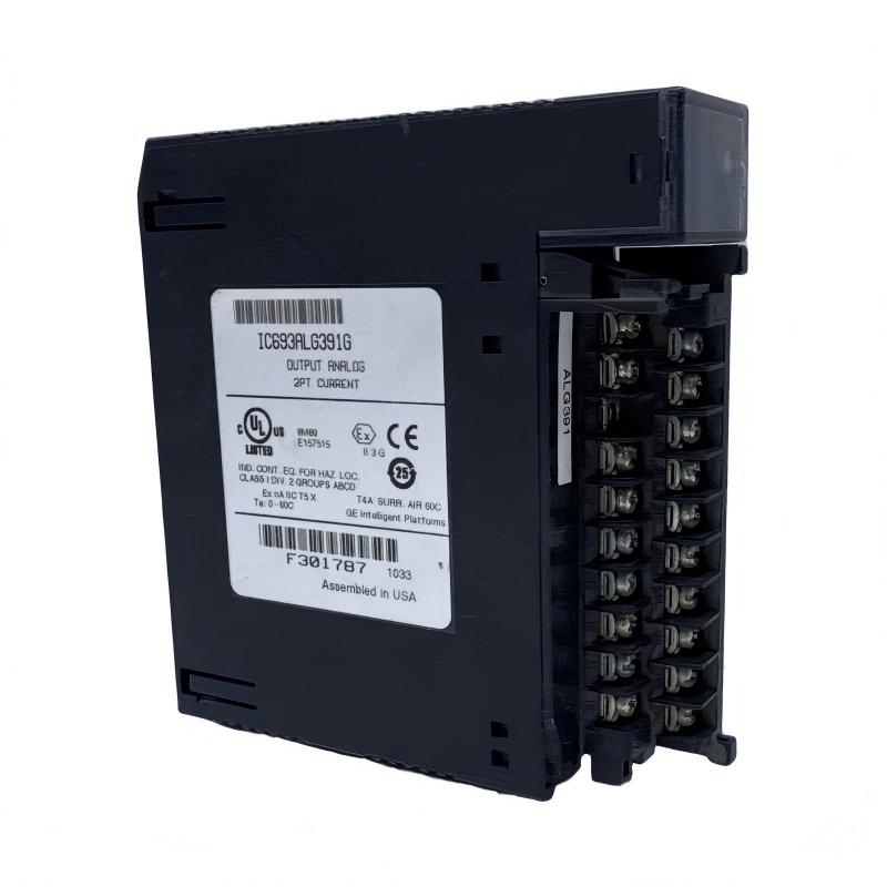
- IC693ALG391G
- Analog Output Module
- USA
- 127 x 35 x 110 mm
- 0.5 kg
- Xiamen, China
- New & In Stock
- T/T, PayPal, Western Union
- 1 Year
- 1-3 Working Days
- DHL, UPS, TNT, FedEx and EMS.
- 24-Hour Service
- COO
- 4
Our advantage

Global Logistics
We have a 10-year logistics and express cooperation agreement, so our products can be shipped to any place in the world.

Brand new and original
Our products are imported in bulk from the place of origin. Because of the cooperative relationship, our products are all original and 100% new.

24-hour service
We provide 7*24 hours service to our customers. We will be there whenever you need us.

Price advantage
All our products are priced very favorably because we have our own warehouse and supply.
| Company Information | |||
| [email protected] | |||
| Mobile | +8615980777398 | ||
| +8615980777398 | |||
| 15980777398 |
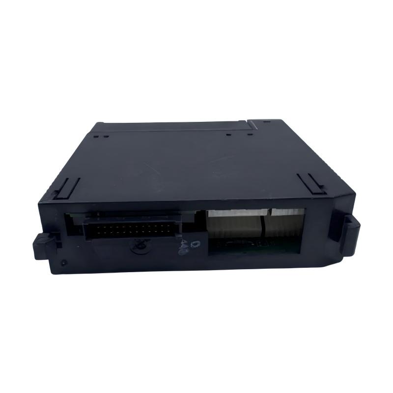
Product Overview
In industrial automation, accurate analog signal output is essential for controlling variable-speed drives, regulating process conditions, and adjusting the operation of field equipment. The GE IC693ALG391G Analog Output Module is associated with the GE Fanuc Series 90-30 Programmable Logic Controller (PLC) platform and is intended for applications requiring analog output signals within a compatible control system.
Analog output modules allow a PLC to translate digital control values into electrical signals that can be interpreted by external devices. These signals may be used to adjust process variables, command compatible drive equipment, or regulate industrial instruments. By connecting PLC logic with analog-controlled equipment, the module supports the implementation of automated control strategies across manufacturing and process applications.
The IC693ALG391G model designation identifies a member of the GE Series 90-30 analog output product range. The exact electrical characteristics, output channel configuration, and compatibility requirements should be verified against the documentation for the specific hardware revision. This is particularly important when replacing an existing module or integrating it into an established control cabinet.
For maintenance engineers, system integrators, and industrial spare-parts buyers, the GE IC693ALG391G is relevant when maintaining compatible Series 90-30 PLC installations that require analog output functionality. Correct identification of the module helps ensure that the replacement meets the system’s signal requirements and operates properly with the connected field equipment.
Technical Specifications
| Parameter | Details |
|---|---|
| Manufacturer | GE / GE Fanuc |
| Model | IC693ALG391G |
| Product Type | Analog Output Module |
| Product Category | PLC Analog Output Module |
| Compatible PLC Platform | GE Fanuc Series 90-30, subject to configuration verification |
| Function | Converts PLC control values into analog output signals |
| Signal Type | Analog output; verify the exact supported signal range |
| Number of Output Channels | Confirm against the documentation for the exact model and revision |
| Output Resolution | Verify against the applicable technical specification |
| Output Accuracy | Verify against the applicable technical specification |
| Dimensions | 127 × 35 × 110 mm |
| Weight | 0.5 kg |
| Installation | Compatible Series 90-30 PLC rack, subject to hardware requirements |
| System Integration | PLC control system and compatible analog-controlled field equipment |
| Power Requirements | Verify the module and rack requirements in the applicable documentation |
| Wiring | According to the specified module connections and system wiring instructions |
| Application | Industrial process control and machine automation |
| Typical Use | Analog control signals for compatible external equipment |
Technical note: The dimensions of 127 × 35 × 110 mm and weight of 0.5 kg are based on the supplied product information. The exact output ranges, channel count, resolution, accuracy, and load requirements have not been independently confirmed for the IC693ALG391G designation. These values should be verified before using the module in an engineering design or ordering a replacement.
Function and Working Principle
The GE IC693ALG391G Analog Output Module is intended to provide analog output functionality within a compatible PLC control system. Its general role is to convert numerical control values generated by the PLC into electrical output signals that can be used by compatible external devices.
In a typical automation process, the PLC receives input information, executes its control program, and calculates the commands required to regulate equipment. The analog output module provides the interface between these digital control calculations and field devices that respond to analog electrical signals.
The main functions of an analog output module include the following.
1. Digital-to-Analog Signal Conversion
A PLC processes control logic and numerical values digitally. An analog output module converts supported digital command values into corresponding analog electrical signals. The available signal types and ranges depend on the specific module.
2. Process Variable Regulation
Analog signals can be used to command equipment that regulates process variables such as flow, pressure, temperature, or speed. The module provides the output interface, while the control algorithm and connected equipment determine how the process responds.
3. Drive and Actuator Control
In compatible configurations, analog output signals may be used as command references for variable-speed drives, motor controllers, or other equipment designed to accept the corresponding signal type. The electrical interface must match the receiving device’s requirements.
4. Integration with Industrial Instruments
Some industrial instruments and control devices accept analog command signals. An appropriately configured PLC analog output module can provide the required interface between the controller and these devices.
5. Automated Control Execution
When incorporated into a suitable control program, the module helps implement continuous or variable control actions rather than limiting the system to simple on/off commands. The overall performance depends on the PLC program, output characteristics, field-device response, and control-system design.
An analog output module should not be confused with an analog input module. Analog input modules measure signals received from field devices, whereas analog output modules generate signals commanded by the PLC.
Role in Industrial Control Systems
The GE IC693ALG391G can serve as an interface between the digital control logic of a compatible Series 90-30 PLC and external equipment that requires analog command signals.
In industrial automation, different components have distinct responsibilities. Sensors measure process conditions, input modules acquire electrical signals, the PLC executes control logic, and output modules provide commands to connected equipment.
Within this architecture, an analog output module can support communication with:
- Variable-speed drives that accept a compatible analog reference
- Industrial controllers with supported analog command inputs
- Modulating actuators and positioning equipment
- Process instruments designed for analog control signals
- Compatible control interfaces and signal-conditioning equipment
- Industrial machines requiring continuously adjustable control commands
The actual devices supported by a particular installation depend on the module’s verified output characteristics and the receiving equipment’s electrical requirements.
For example, a PLC may use a process measurement and a programmed control algorithm to determine the desired speed of a motor-driven system. Where the drive accepts the module’s output signal, the analog output can provide a speed reference. The drive then regulates the motor according to its own configuration and control functions.
This arrangement allows analog output functionality to become part of a broader control strategy. However, the module itself does not independently measure process conditions, execute the complete PLC control program, or directly supply motor power.
Industrial Applications
The GE IC693ALG391G is relevant to industrial automation applications that require analog output functionality in compatible Series 90-30 PLC systems.
Manufacturing Automation
Manufacturing lines often contain equipment that requires adjustable speed, position, pressure, or other operating commands. Where compatible signal interfaces are available, analog output modules can support the control of drives and other adjustable equipment.
Process Control
Industrial processes frequently require continuously adjustable control actions. A PLC can calculate an appropriate command based on sensor information and programmed logic, while an analog output module supplies the corresponding electrical signal to compatible process equipment.
Pump and Fan Systems
Pump and fan installations may use variable-speed drives to regulate flow or airflow. An analog output signal can serve as a reference when supported by both the PLC module and the drive. The final control strategy depends on the application requirements and drive configuration.
Material Handling Equipment
Conveyors and other material handling systems may require adjustable operating speeds. A PLC-based control system can use analog commands to interface with compatible speed-control equipment, subject to the module’s electrical specifications.
Industrial Machine Upgrades
Facilities that continue to operate established Series 90-30 PLC systems may need to replace aging analog output hardware while preserving existing machine-control logic. Correctly identifying the original module is important when maintaining such equipment.
General Process Regulation
Temperature, pressure, and flow-control applications may use analog commands to operate compatible controllers or actuators. The module provides the electrical output interface, while the connected equipment and control program determine the resulting process response.
The suitability of the IC693ALG391G for any of these applications must be confirmed against the exact output signal requirements and the installed PLC configuration.
Installation and System Integration
Proper installation is important for maintaining signal accuracy, electrical safety, and reliable operation. Before installing or replacing the GE IC693ALG391G, engineers should confirm that the module is appropriate for the target Series 90-30 PLC configuration.
1. Verify the Module Identification
Check the complete model designation, including the final letter G, along with the product label and available revision information. Similar model numbers may have different electrical characteristics or hardware requirements.
2. Confirm Rack Compatibility
Check the PLC CPU, rack configuration, available slot, and applicable installation instructions. Ensure that the selected module is supported by the intended system configuration.
3. Review the Electrical Specifications
Confirm the supported output signal range, channel configuration, load requirements, and relevant electrical limits. The connected device must accept the signal provided by the module.
4. Prepare the Installation Environment
Follow the manufacturer’s electrical isolation procedures and the site’s lockout requirements before handling the equipment. Use appropriate electrostatic-discharge precautions and inspect the rack and connectors before installation.
5. Connect the Field Wiring
Follow the correct terminal assignments and wiring instructions for the exact module. Observe applicable grounding, shielding, and cable-routing practices to help reduce electrical noise and prevent wiring errors.
6. Configure the PLC Program
Configure the relevant output addresses and scaling in accordance with the installed module’s documentation and the PLC programming environment. Verify that the programmed values correspond to the intended physical output range.
7. Test the Output Signals
After installation, carry out the specified commissioning checks. Confirm that the output signal corresponds to the commanded value and that the connected equipment responds correctly within its permitted operating range.
8. Document the Installation
Record the module identification, hardware revision, output configuration, wiring details, and commissioning results. This information helps future maintenance personnel diagnose problems and select suitable replacement parts.
The exact wiring, configuration steps, supported signal ranges, and commissioning procedure depend on the hardware revision and the applicable system documentation. These details should not be inferred from the model number alone.
Compatible System Components
The GE IC693ALG391G operates as part of a larger PLC and field-control architecture. Its integration depends on the correct combination of controller hardware, power supply, wiring, and external devices.
| Component or Equipment | Function | Relationship to IC693ALG391G |
|---|---|---|
| GE Series 90-30 PLC CPU | Executes the control program and calculates output commands | Provides the control logic associated with the analog output function |
| Series 90-30 Rack and Backplane | Houses supported modules and provides internal system connections | Must satisfy the module’s installation and compatibility requirements |
| PLC Power Supply | Supplies power to the PLC rack | Must meet the requirements of the installed system |
| Analog Input Module | Acquires analog signals from field instruments | May provide process feedback used by the PLC control program |
| Variable-Speed Drive | Regulates motor speed and torque | Can receive an analog reference if its input matches the module’s verified output |
| Signal Conditioner | Converts or isolates signals where required | May be used when the source and receiving-device interfaces are not directly compatible |
| Modulating Actuator or Controller | Adjusts a process variable based on a command signal | Can be controlled if its input characteristics match the output module |
| Field Wiring and Terminal Connections | Carry analog signals between the PLC and field devices | Must follow the correct terminal assignments and electrical requirements |
| Engineering Workstation | Supports PLC programming and diagnostics | Used to configure and verify the relevant control logic and output values |
These components describe common system relationships rather than a confirmed bill of materials for every IC693ALG391G installation. The exact components depend on the application’s design and the verified module specifications.
Recommended Alternative Models
When selecting a replacement for the GE IC693ALG391G, the original model should be the first reference point. If it is unavailable, the alternative must be evaluated according to its analog output characteristics, channel configuration, rack compatibility, and control-system requirements.
| Model | Type | Key Feature | Application |
|---|---|---|---|
| IC693ALG391G | Analog Output Module | Original requested designation | Preferred identification for a like-for-like replacement, subject to label verification |
| IC693ALG391 | Analog Output Module family designation | Related base-model reference | Check the exact suffix, electrical specifications, and revision before purchasing |
| IC693ALG392 | Analog Output Module | Related Series 90-30 analog output product designation | Potential candidate for evaluation only after comparing signal ranges and system compatibility |
| IC693ALG223 | Analog Input Module | Acquires analog signals rather than generating them | Relevant to measurement and feedback applications, not a direct substitute |
| Compatible Series 90-30 Analog Output Module | PLC analog output hardware | Provides analog command signals within a compatible configuration | Consider only after confirming the required electrical and mechanical characteristics |
Important selection guidance: The IC693ALG391 and IC693ALG392 designations should be treated as related product references, not confirmed interchangeable replacements for the IC693ALG391G. Their exact specifications and revision compatibility must be checked before ordering.
The IC693ALG223 is an analog input module, so it performs a different function and should not be presented as a direct replacement for an analog output module. Similarly, a generic Series 90-30 analog output module is suitable only if its output characteristics, hardware requirements, and application compatibility meet the original system’s needs.
A replacement should be approved based on the target PLC configuration and verified electrical requirements rather than the similarity of the model numbers alone.
Key Advantages
The GE IC693ALG391G Analog Output Module can provide several benefits when correctly integrated into a compatible Series 90-30 PLC system.
- Analog command generation: Converts PLC control values into supported analog output signals.
- Industrial control integration: Connects digital PLC logic with compatible analog-controlled equipment.
- Variable process regulation: Can support adjustable commands for drives, controllers, and other field devices.
- Established PLC platform support: Provides a relevant spare-part reference for facilities maintaining compatible Series 90-30 installations.
- Targeted maintenance: Helps identify the required analog output component during troubleshooting and replacement.
- Flexible application potential: Can be incorporated into suitable manufacturing and process-control architectures.
- Improved control-system integration: Supports the implementation of control strategies that require variable output commands.
These advantages depend on verified module specifications, correct wiring, appropriate PLC programming, and compatibility with the receiving equipment.
Technical FAQs
1. What is the GE IC693ALG391G?
The GE IC693ALG391G is identified as an analog output module associated with the GE Fanuc Series 90-30 PLC platform. Its intended role is to provide analog output functionality in a compatible control system.
2. What are the dimensions and weight of the IC693ALG391G?
The supplied specifications list dimensions of 127 × 35 × 110 mm and a weight of 0.5 kg. These figures should be checked against the physical unit when exact mounting or shipping requirements are important.
3. What is the main function of an analog output module?
An analog output module converts digital command values from the PLC into electrical output signals accepted by compatible external devices. The supported signal ranges depend on the specific module.
4. Can the IC693ALG391G control a variable-speed drive?
It may be used to provide a command reference to a drive if the module’s verified output characteristics match the drive’s analog input requirements. The exact signal range and wiring must be checked before integration.
5. Is the IC693ALG391G an analog input module?
No. It is identified as an analog output module. An analog input module acquires signals from field devices, whereas an analog output module generates signals commanded by the PLC.
6. Is the IC693ALG392 a direct replacement for the IC693ALG391G?
That should not be assumed. The exact output specifications, channel configuration, revision, and system compatibility must be compared before treating another model as a replacement.
7. What should be checked before ordering?
Confirm the full model number, the final letter G, the product label, hardware revision, PLC CPU, rack configuration, output signal requirements, and the connected equipment’s electrical specifications.
8. Why is output signal compatibility important?
The receiving device must accept the signal range and electrical characteristics provided by the output module. A mismatch can result in incorrect commands, unreliable operation, or potential equipment problems.
9. What can cause an analog output problem?
Potential causes include incorrect wiring, incompatible load requirements, configuration errors, damaged field devices, electrical noise, or a fault in the module or PLC system. Diagnosis should follow the applicable maintenance procedure.
10. Is the IC693ALG391G suitable for new automation projects?
It may be considered when a project intentionally retains compatible Series 90-30 equipment. For a new installation, engineers should also assess lifecycle support, spare-parts availability, system integration, and long-term maintenance requirements.
Conclusion
The GE IC693ALG391G Analog Output Module is a PLC-related component intended to provide analog output functionality within compatible GE Fanuc Series 90-30 control systems. By converting PLC control values into supported electrical output signals, analog output hardware can help connect digital control logic with drives, controllers, and other compatible industrial equipment.
The supplied product dimensions are 127 × 35 × 110 mm, and the supplied weight is 0.5 kg. Before purchasing or installing a replacement, engineers should verify the complete model designation, hardware revision, output characteristics, rack compatibility, and electrical requirements of the connected field equipment.
For industrial maintenance teams, system integrators, and spare-parts suppliers, accurate identification and careful compatibility checks help reduce purchasing errors and support the reliable operation of existing industrial automation systems.