
NewsNEWCENTER
Featured products
Contact Us
Allen Bradley MPL-A560E-M-X189 Servo Motor Troubleshooting Guide
2026-10-12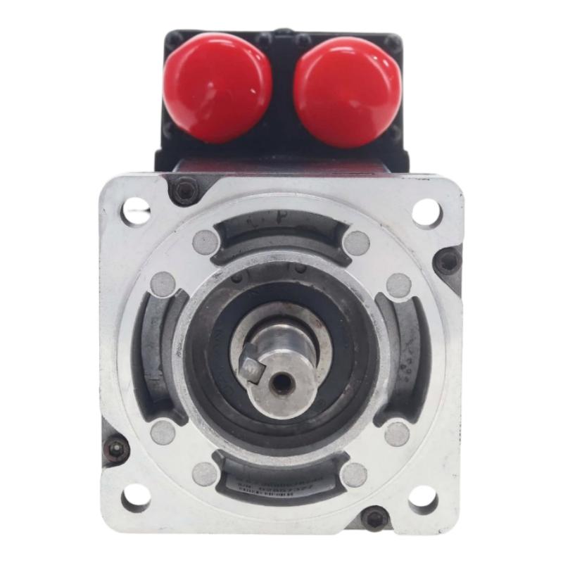
Allen Bradley MPL-A560E-M-X189 Servo Motor troubleshooting should cover the complete motion-control system, including the servo drive, motor power circuit, feedback wiring, mechanical load, and motion configuration. If the motor fails to start, produces excessive vibration, overheats, or cannot maintain the commanded position, the cause may be external to the motor. A systematic fault-diagnosis process helps maintenance personnel identify the actual source before replacing components.
Understanding MPL-A560E-M-X189 Servo System Faults
A servo axis relies on coordinated operation between the controller, drive, motor, feedback interface, and mechanical load. A fault in any of these elements may interrupt movement or reduce positioning performance.
Motion Controller
       ↓
Servo Drive
       ↓
Motor Power Circuit
       ↓
MPL-A560E-M-X189
       ↓
Mechanical Load

Motor Feedback ─────→ Servo Drive
Drive Diagnostics ──→ Controller
The most effective diagnostic approach is to determine where the expected behavior first differs from the actual behavior.
Common Allen Bradley MPL-A560E-M-X189 Symptoms
- Motor does not rotate when commanded.
- Servo drive reports a motor or feedback fault.
- Axis starts but stops unexpectedly.
- Positioning accuracy is inconsistent.
- Motor produces unusual noise or vibration.
- Motor or drive temperature increases abnormally.
- Movement becomes unstable during acceleration.
- Motor direction differs from the expected direction.
- Intermittent faults occur during production.
Common Servo Motor Fault Causes
| Symptom | Possible Cause | Initial Check |
|---|---|---|
| Motor will not start | Drive inhibit, missing enable, power connection fault | Check drive status and enable conditions |
| Feedback fault | Damaged cable, loose connector, incompatible interface | Inspect feedback wiring |
| Positioning error | Incorrect scaling, load problem, tuning issue | Compare command and feedback values |
| Excessive vibration | Misalignment, loose mounting, unstable tuning | Inspect mechanical installation |
| Overheating | Excessive load, unsuitable duty cycle, cooling problem | Review operating conditions |
| Intermittent shutdown | Loose connection, intermittent cable fault, drive protection | Review fault history and connections |
MPL-A560E-M-X189 Troubleshooting Flowchart
Servo Axis Fault
       ↓
Record Drive Fault Code
       ↓
Check Drive Enable / Safety Status
       ↓
Drive Ready?
    ↙       ↘
   NO       YES
   ↓         ↓
Check Drive  Inspect Power
Status       and Feedback
                ↓
         Electrical Path OK?
            ↙        ↘
           NO        YES
           ↓          ↓
      Correct Wiring Inspect Mechanics
                     and Load
                         ↓
                  Check Parameters
                         ↓
                  Controlled Retest
Step-by-Step Servo Motor Fault Diagnosis
1. Record the Drive Fault Information
Record the exact fault code, message, operating state, and conditions preceding the event. Consult the documentation for the installed drive to interpret the code correctly. Avoid repeatedly resetting the drive without first recording the available diagnostic information.
2. Check Drive Enable and Safety Conditions
If the motor does not move, confirm that the drive is ready and that all required enable signals, safety interlocks, and operating conditions are satisfied. A disabled axis can appear to have a motor fault even when the motor is electrically sound.
3. Inspect Motor Power Connections
Follow the approved electrical isolation procedure before inspecting power wiring. Check the motor cable, connectors, grounding, and drive-side connections for looseness, insulation damage, contamination, or overheating.
Do not disconnect motor power or feedback connectors while energized unless the applicable equipment documentation explicitly permits the operation.
4. Diagnose Feedback Problems
If the drive reports a feedback fault, inspect the cable and connectors and verify that the feedback interface is compatible with the motor and drive. Check for bent contacts, contamination, damaged insulation, and excessive cable strain.
Where supported by the drive, use its diagnostic information to determine whether feedback is being recognized correctly. Do not assume that the motor itself has failed before excluding cable and configuration problems.
5. Inspect Mechanical Conditions
Vibration, excessive following error, or difficulty accelerating may result from mechanical resistance rather than an electrical motor fault.
- Check mounting hardware for looseness.
- Inspect coupling alignment.
- Look for mechanical binding or unexpected load resistance.
- Confirm that the driven mechanism operates within its intended load range.
- Investigate unusual shaft or bearing noise.
6. Review Configuration and Servo Tuning
If the power, feedback, and mechanical checks are satisfactory, review the motor identification, feedback configuration, axis scaling, motion limits, and tuning parameters. Incorrect configuration can cause inaccurate positioning, oscillation, overshoot, or unexpected drive trips.
Make parameter adjustments only under an approved procedure, changing one relevant setting at a time and recording the original values.
Diagnosing Positioning Errors
When the motor runs but the axis does not reach the commanded position, compare commanded motion with actual feedback. Investigate scaling, coupling condition, mechanical backlash, load variation, and following error before changing servo gains.
Positioning Error
       ↓
Compare Command and Feedback
       ↓
Feedback Valid?
   ↙         ↘
  NO         YES
  ↓           ↓
Check Cable  Check Load
and Feedback  and Alignment
                 ↓
            Review Scaling
                 ↓
            Review Tuning
                 ↓
             Retest Axis
Increasing servo gains without identifying the root cause can make vibration or instability worse. Mechanical condition and feedback validity should be established first.
Illustrative MPL-A560E-M-X189 Troubleshooting Case
The following scenario is an illustrative diagnostic example, not a verified customer case or a model-specific performance specification.
Reported Symptom:
Axis produces excessive vibration during movement.

Drive Diagnostics:
No persistent feedback fault recorded

Power Wiring:
Initial inspection satisfactory

Mechanical Inspection:
Coupling alignment requires correction

Diagnostic Direction:
Correct the mechanical alignment before
adjusting servo tuning parameters.

Verification:
Repeat a controlled low-speed test and
check motion stability.
This example illustrates why mechanical alignment should be checked before treating every vibration problem as an electrical or control-system failure.
Repair and Replacement Recommendations
Replacing the servo motor should be considered only after the drive, wiring, feedback circuit, mechanical system, and configuration have been checked. If the actual fault lies in an external cable, coupling, or drive parameter, replacing the motor will not solve the underlying problem.
- Place the machine in a safe maintenance state.
- Isolate electrical and mechanical energy according to site procedures.
- Record the motor and drive identification.
- Document the wiring and mechanical mounting arrangement.
- Inspect cables, connectors, shaft, and mounting surfaces.
- Correct any confirmed external faults.
- Replace the motor only when diagnostic evidence supports the decision.
- Install a compatible replacement using the approved procedure.
- Verify grounding, feedback connections, and drive configuration.
- Perform controlled movement and application-level testing.
Post-Repair Verification Checklist
- Drive reports the expected ready status.
- Motor and feedback connections are secure.
- No persistent motor-related faults remain.
- Motor direction is correct.
- Mechanical movement is smooth.
- Commanded and actual positions correspond correctly.
- Acceleration and deceleration are stable.
- Motor temperature and noise are normal for the application.
- Safety functions and travel limits operate correctly.
- The machine completes a controlled functional test.
Allen Bradley MPL-A560E-M-X189 Troubleshooting FAQs
Why does the MPL-A560E-M-X189 Servo Motor fail to start?
Check drive status, enable conditions, safety interlocks, fault history, power wiring, and feedback connections before concluding that the motor is defective.
What can cause a servo feedback fault?
Potential causes include damaged cables, loose connectors, incompatible feedback components, electrical interference, or incorrect drive configuration.
Why does the servo motor vibrate during operation?
Possible causes include shaft misalignment, loose mounting hardware, mechanical binding, unsuitable tuning, or unreliable feedback. Inspect the mechanical system and feedback path before adjusting parameters.
When should the motor be replaced?
Replacement should be considered when the evidence indicates a motor-side fault after the drive, cables, feedback interface, mechanical load, and configuration have been evaluated.
Is it safe to disconnect motor cables during operation?
No. Disconnecting power or feedback connections while energized can create electrical hazards, damage equipment, and cause uncontrolled motion. Follow approved isolation and testing procedures.
Technical Summary
Effective Allen Bradley MPL-A560E-M-X189 Servo Motor troubleshooting requires a systematic examination of drive diagnostics, enable signals, power wiring, feedback, mechanical loading, and servo configuration. By identifying the first point where actual behavior differs from the expected motion, maintenance personnel can reduce unnecessary replacements, resolve faults more efficiently, and restore reliable machine operation.