

ProductPRODUCT
Featured products
Contact Us
- Schneider
- TM5ACBN1
- Bus Base Module
- France
- 99 × 38 × 75 mm
- 0.132 kg
- Xiamen, China
- New & In Stock
- T/T, PayPal, Western Union
- 1 Year
- 1-3 Working Days
- DHL, UPS, TNT, FedEx and EMS.
- 24-Hour Service
- COO
- 5
Our advantage

Global Logistics
We have a 10-year logistics and express cooperation agreement, so our products can be shipped to any place in the world.

Brand new and original
Our products are imported in bulk from the place of origin. Because of the cooperative relationship, our products are all original and 100% new.

24-hour service
We provide 7*24 hours service to our customers. We will be there whenever you need us.

Price advantage
All our products are priced very favorably because we have our own warehouse and supply.
| Company Information | |||
| [email protected] | |||
| Mobile | +8615980777398 | ||
| +8615980777398 | |||
| 15980777398 |
Product Overview
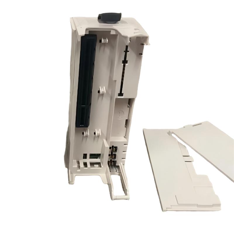
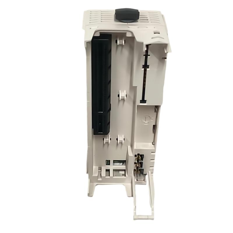
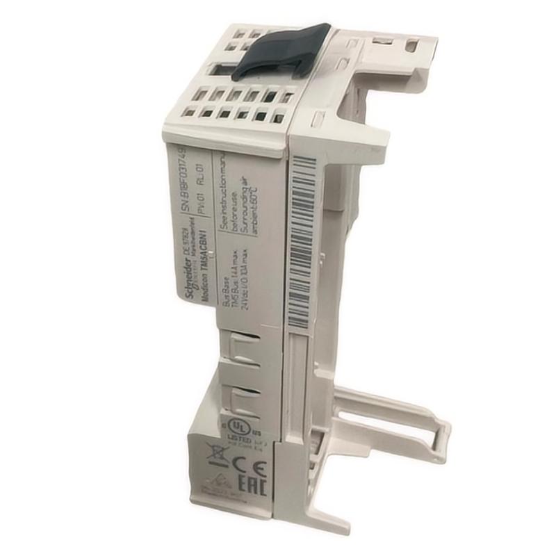
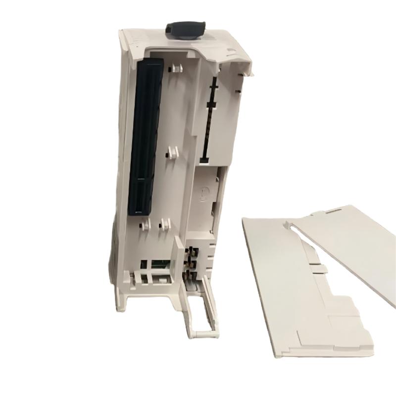
The Schneider Electric TM5ACBN1 Bus Base Module is an industrial automation component associated with the Modicon TM5 modular I/O system. Bus base modules provide an important physical and electrical interface within a modular automation architecture, helping connect compatible electronic modules and establish the necessary interconnection between system components.
In industrial control applications, modular I/O systems allow engineers to organize input, output, and related interface functions according to machine requirements. A properly configured modular system supports structured wiring, easier maintenance, and flexible integration into a wider PLC control architecture.
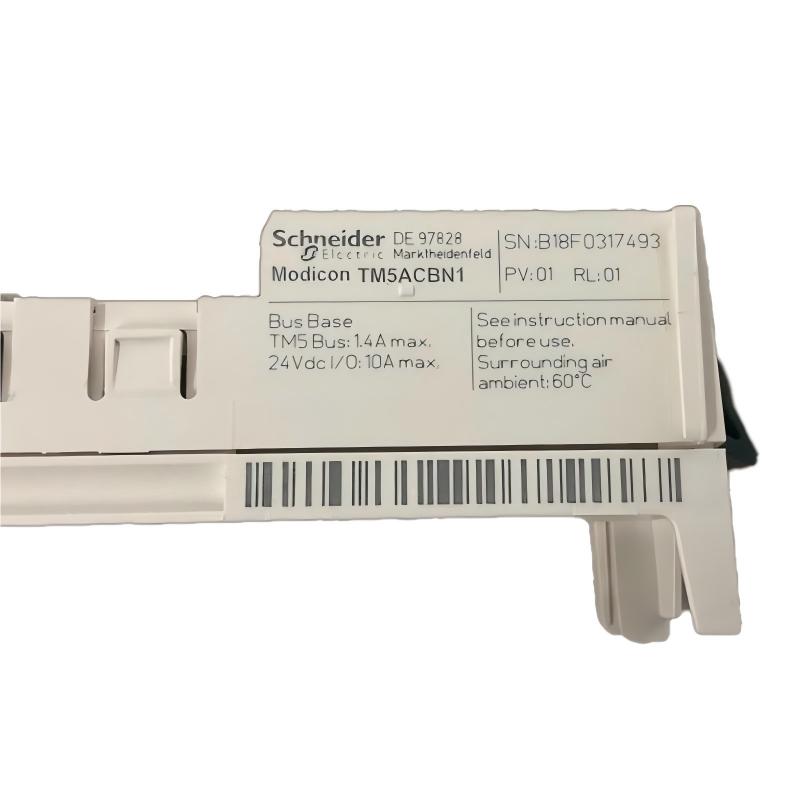
The TM5ACBN1 is identified by the supplied product description as a bus base module. Its listed dimensions are 99 × 38 × 75 mm, and its listed weight is 0.132 kg. These physical characteristics are useful when planning cabinet layouts, estimating replacement requirements, and managing spare parts.
The bus base module should be selected according to the specific hardware configuration and the requirements of the associated Schneider Electric automation system. Before installation or replacement, verify the complete product reference, module arrangement, connection requirements, and compatibility with the existing TM5 system.
Technical Specifications
| Parameter | Specification |
|---|---|
| Manufacturer | Schneider Electric |
| Model | TM5ACBN1 |
| Product Type | Bus Base Module |
| Product Family | Modicon TM5-related automation hardware, subject to confirmation |
| Primary Function | Base and interconnection support for compatible modular hardware |
| System Role | Modular automation system interface |
| Dimensions | 99 × 38 × 75 mm |
| Weight | 0.132 kg |
| Installation | Compatible modular mounting arrangement; verify exact requirements |
| Typical Application | PLC-based machine automation and modular I/O installations |
| Compatibility | Confirm against the exact module combination and system documentation |
The table reflects the supplied product description and physical specifications. Electrical ratings, supported module combinations, bus characteristics, terminal assignments, and other detailed operating parameters should be verified against the exact product documentation rather than assumed from the model name.
What Is the Schneider TM5ACBN1 Bus Base Module?
A bus base module is a component used within a modular automation arrangement to support the installation and interconnection of compatible electronic modules. Depending on the system design, the base may provide mechanical support and electrical connections required for communication or signal distribution between associated components.
In a modular PLC system, different hardware components perform different roles. The controller executes the automation program, I/O modules acquire field signals or drive compatible outputs, and base or interconnection components provide the physical and electrical infrastructure needed to assemble the system.
The TM5ACBN1 is described as a bus base module, so its selection should focus on the requirements of the associated hardware rather than treating it as a standalone PLC controller or a general-purpose I/O module.
A simplified modular arrangement can be represented as:
PLC Controller → Modular Interconnection Structure → Compatible I/O Modules → Field Devices
The exact layout, connection method, and role of each component depend on the verified system configuration.
Function and Working Principle
1. Mechanical Support for Modular Hardware
A modular automation system requires components to be mounted securely and arranged in accordance with the manufacturer’s installation requirements. A suitable base component helps maintain the intended physical arrangement of the associated modules.
Correct mounting is important for maintaining proper alignment, securing connections, and supporting access for wiring and maintenance.
2. Electrical Interconnection
Depending on its specific design, a bus base module may provide electrical connection points between compatible components. The exact electrical functions and connection arrangement of the TM5ACBN1 must be confirmed from the relevant product documentation.
Using the correct base is essential because similar-looking components may have different terminal arrangements or compatibility requirements.
3. Support for Modular System Organization
Modular automation hardware allows a control system to be assembled from components selected for a particular machine or process. Correct base and interconnection hardware helps organize the modules into a coherent installation.
This structure can simplify cabinet planning and make it easier to identify individual components during commissioning and maintenance.
4. Integration with the Automation Architecture
The bus base module forms part of a larger hardware arrangement rather than performing the PLC’s control logic independently. The controller and compatible electronic modules provide the main processing, input acquisition, output control, and other automation functions.
The complete system must be configured according to the capabilities and restrictions of the actual installed hardware.
Role in Industrial Control Systems
Within an industrial automation installation, base and interconnection components provide the infrastructure needed to assemble modular control hardware. Their condition and compatibility can affect the reliability of the overall installation.
The TM5ACBN1 may be considered as part of a modular automation arrangement when its exact identity and compatibility have been confirmed.
Its system-level role can be understood through the following component relationships:
| System Element | Typical Responsibility |
|---|---|
| PLC Controller | Executes the control program |
| Bus Base Module | Supports the intended modular assembly and interconnection functions |
| Digital Input Module | Acquires discrete signals from compatible field devices |
| Digital Output Module | Controls compatible discrete loads through the specified interface |
| Analog Input Module | Acquires continuous process measurements |
| Analog Output Module | Supplies compatible variable control signals |
| Field Wiring | Connects sensors, switches, actuators, and other devices |
| Engineering Software | Supports hardware configuration and diagnostics |
| HMI Panel | Displays machine status and operator information |
The exact component arrangement depends on the application. The table describes general functional roles and does not establish compatibility with every listed device.
Industrial Applications
Machine Automation
Modular automation hardware is commonly used in industrial machines that require organized input and output interfaces. Suitable base components help maintain a consistent physical structure for the installed control hardware.
Packaging Equipment
Packaging machines may contain sensors, switches, actuators, and other field devices distributed across multiple machine sections. A properly designed modular control system can help organize these interfaces and simplify maintenance.
Material Handling Systems
Conveyors and material handling equipment often require coordinated control of sensors, motors, position switches, and other devices. Modular control architectures can provide a structured way to integrate these signals into the PLC system.
Manufacturing and Assembly Lines
Production equipment may use modular control hardware to support different workstations and machine functions. Correct base and interconnection components help ensure that the selected hardware is assembled according to the intended configuration.
Industrial Equipment Upgrades
When an existing control panel is modified or expanded, modular hardware may be reused or replaced as part of a broader engineering project. Any proposed change should be evaluated for physical fit, electrical compatibility, configuration requirements, and operational impact.
Installation and System Integration
Correct installation helps maintain the integrity of a modular automation system. Before installing the TM5ACBN1, confirm its complete product reference and the specific hardware arrangement in which it will be used.
Verify the Product Identity
Check the label, full model number, revision information where applicable, and existing system records. Confirm that the part is actually the required bus base module and that it matches the installed hardware configuration.
Do not determine compatibility solely from the product’s appearance or dimensions.
Confirm System Compatibility
Before assembly, verify the required base type, associated electronic modules, mounting arrangement, connection method, and system configuration. Check whether any restrictions apply to the intended module combination.
A component that fits mechanically may still be electrically or functionally unsuitable.
Prepare the Installation Area
Ensure that the control cabinet is suitable for the equipment and that the installation environment meets the applicable requirements. Maintain sufficient clearance for wiring, inspection, and future maintenance.
Follow the prescribed electrical isolation procedures before handling or replacing components inside an energized control cabinet.
Inspect Connections and Mounting
Check the base and associated modules for damaged connectors, cracked housings, contamination, or other visible defects. Ensure that all components are mounted and secured according to the manufacturer’s instructions.
Do not force modules or connectors into place. Resistance during assembly may indicate incorrect alignment, an incompatible component, or damage.
Configure and Commission the System
After assembly, verify the complete hardware configuration and check for controller or system diagnostics where available. Confirm that the associated modules are recognized and that the automation system operates as expected.
Record any replacement, wiring, or configuration changes in the maintenance documentation.
Troubleshooting the TM5ACBN1 Bus Base Module
Problems involving a bus base module should be investigated as part of the complete modular hardware assembly. Not every system fault is caused by the base itself.
Module Not Recognized
If an associated module is not recognized, possible causes include an incorrect hardware configuration, incompatible module combination, poor seating, damaged connectors, or a fault in another system component.
Check the hardware arrangement against the system records. Inspect the connections and review the available controller diagnostics before replacing the base.
Intermittent System Faults
Intermittent faults may be associated with loose connections, vibration, damaged hardware, contamination, or environmental conditions outside the equipment’s specified limits.
Inspect the mounting arrangement and connections using approved maintenance procedures. Record diagnostic messages and determine whether the fault follows a particular module or connection point.
Physical Connection Problems
Difficulty fitting or securing a module may indicate incorrect alignment, an unsuitable base, damaged locking features, or a mismatch between hardware variants.
Do not force the assembly together. Compare the component references and mounting requirements, then inspect the relevant parts for physical damage.
Configuration Errors
A system may report a configuration problem if the installed hardware does not match the configured arrangement or if a component is unsupported in the selected system.
Verify the exact model numbers, hardware selections, and system requirements. Correct the configuration only after confirming the actual installed components.
Suspected Base Module Failure
If the problem persists after checking the associated modules, connections, mounting, and configuration, the base module may require further evaluation.
Where practical and permitted by the system design, qualified technicians can use a known-good compatible component as part of a controlled diagnostic procedure. Replacement should follow the applicable maintenance and commissioning requirements.
Maintenance Recommendations
Regular inspection helps maintain the reliability of modular control hardware.
Inspect physical condition: Look for cracked housings, damaged locking features, connector deformation, contamination, or evidence of overheating.
Check mounting security: Confirm that the base and associated modules remain properly secured.
Inspect connections: Look for loose, damaged, or contaminated interfaces and correct any issues using approved procedures.
Maintain cabinet conditions: Keep the installation within the specified temperature, humidity, vibration, and contamination limits.
Review system diagnostics: Record recurring configuration or module-recognition faults and investigate patterns rather than repeatedly resetting the system.
Document replacements: Record the installed model, revision where applicable, replacement date, and commissioning results.
Maintenance should be performed by qualified personnel following the requirements of the complete automation system.
Compatible System Components
The TM5ACBN1 should be matched to the exact modular hardware architecture for which it is specified. The following component categories illustrate the types of equipment that may be present in a broader automation installation; they are not a confirmation that every model is directly compatible with this base module.
| Component Category | Purpose |
|---|---|
| Compatible Schneider Electric Controller | Executes machine-control logic |
| Compatible Modular I/O Hardware | Acquires field signals or controls outputs |
| Digital Input Modules | Monitor discrete device states |
| Digital Output Modules | Provide discrete output control |
| Analog Input Modules | Measure compatible analog signals |
| Analog Output Modules | Provide variable control signals |
| Terminal Blocks | Organize field wiring |
| Industrial Power Supply | Supplies appropriately rated control power |
| HMI Panel | Provides operator monitoring and interaction |
| Engineering Software | Supports configuration, programming, and diagnostics |
Before purchasing related hardware, verify the full model numbers, supported combinations, required accessories, and system limitations.
Replacement and Procurement Considerations
When sourcing a replacement for the Schneider Electric TM5ACBN1 Bus Base Module, exact identification is essential.
The following details should be checked before ordering:
- Complete product reference
- Product designation and revision information
- Physical dimensions and mounting arrangement
- Connector and terminal configuration
- Associated module types
- Controller and system compatibility
- Condition of the original component
- Required commissioning and configuration procedures
The supplied dimensions are 99 × 38 × 75 mm, and the supplied weight is 0.132 kg. These values can support stock management, shipping planning, and preliminary cabinet-layout preparation.
Physical similarity does not guarantee interchangeability. A replacement must satisfy the system’s mechanical, electrical, and functional requirements.
Key Advantages
Modular System Organization
Suitable base hardware helps organize compatible components into a structured automation assembly.
Compact Physical Dimensions
The listed dimensions of 99 × 38 × 75 mm support preliminary space planning for appropriate control-panel installations.
Support for Maintainable Hardware Layouts
A correctly assembled modular system can make component identification, inspection, and replacement more straightforward.
Integration into Industrial Automation
When matched with the correct hardware, a bus base module contributes to the physical and electrical infrastructure of a modular control installation.
Easier Replacement Planning
Accurate identification and documented system configuration help reduce the risk of ordering an incompatible replacement.
Technical FAQs
What is the Schneider TM5ACBN1?
The TM5ACBN1 is identified by the supplied product description as a Schneider Electric bus base module associated with modular industrial automation hardware. Its exact system role should be confirmed against the product documentation.
What is the main function of a bus base module?
A bus base module generally provides a mounting or interconnection interface for compatible modular hardware. The precise mechanical and electrical functions depend on the specific product.
What are the dimensions of the TM5ACBN1?
The supplied dimensions are 99 × 38 × 75 mm.
How much does the TM5ACBN1 weigh?
The supplied weight is 0.132 kg.
Is the TM5ACBN1 a PLC CPU?
It is described as a bus base module, not a standalone PLC CPU. The controller and other compatible modules perform the main control, input, output, and processing functions of the system.
Can the TM5ACBN1 be used with any Schneider Electric PLC?
No. Compatibility must be confirmed for the exact controller family, modular hardware arrangement, and system configuration. The Schneider Electric brand alone does not establish interchangeability.
What should be checked if an associated module is not recognized?
Inspect the hardware configuration, component references, mounting, connector condition, and available system diagnostics. Confirm that the installed components form a supported combination before replacing hardware.
Can a physically similar base module replace the TM5ACBN1?
Not without verification. The replacement must match the required mechanical interface, electrical connections, module compatibility, and system requirements.
Conclusion
The Schneider Electric TM5ACBN1 Bus Base Module is identified as a modular automation component intended to support the assembly and interconnection of compatible control hardware. Base and interconnection components are important to the organization, installation, and maintenance of modular industrial control systems.
With supplied dimensions of 99 × 38 × 75 mm and a weight of 0.132 kg, the TM5ACBN1 provides useful physical specifications for inventory management and installation planning. Reliable integration depends on confirming the exact product identity, supported hardware combinations, connection requirements, and mounting instructions.
For replacement or system expansion, verify the complete model reference and applicable technical documentation before installation. Correct identification, careful assembly, and systematic commissioning help maintain the reliability of the wider industrial automation system.