

ProductPRODUCT
Featured products
Contact Us
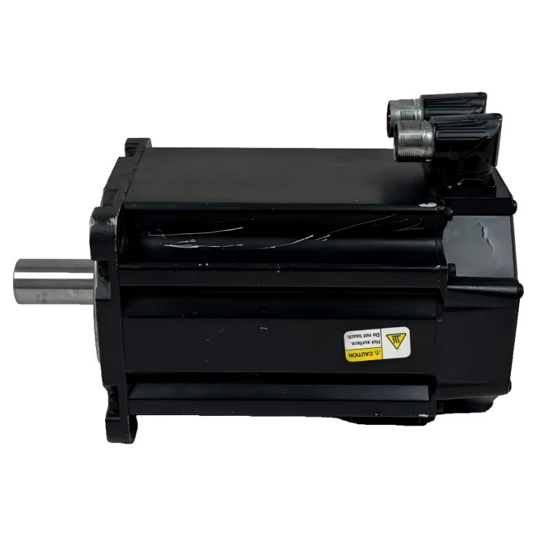
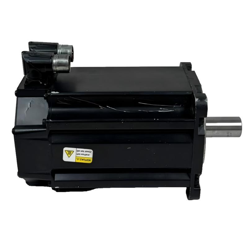
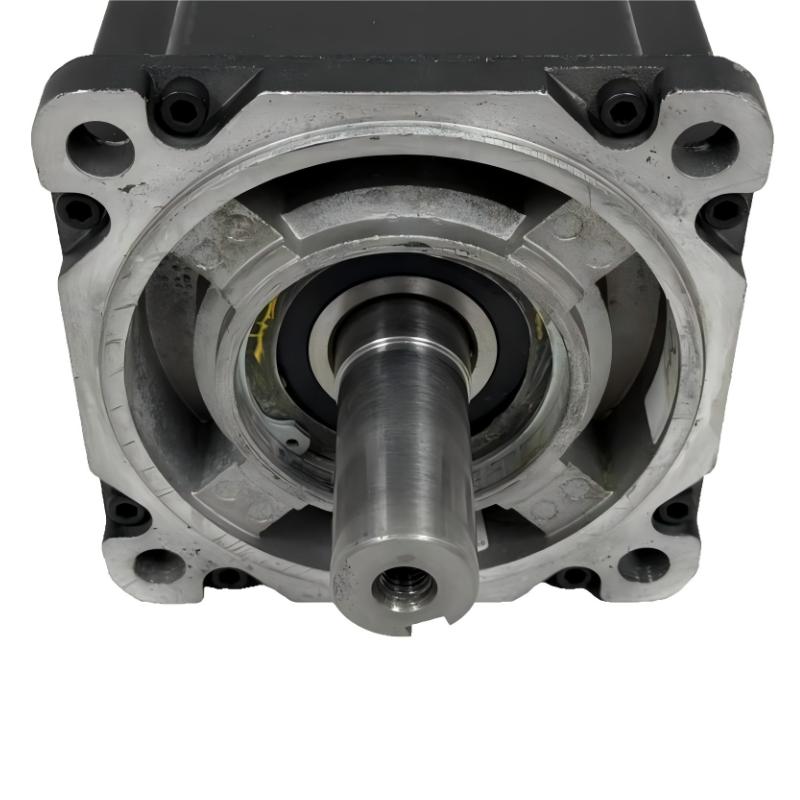
- Allen Bradley
- MPL-B980E-MJ74AA
- Low-Inertia Brushless Servo Motors Product
- USA
- 215 mm ×203.2 mm × 325 mm
- 42.7 kg
- Xiamen, China
- New & In Stock
- T/T, PayPal, Western Union
- 1 Year
- 1-3 Working Days
- DHL, UPS, TNT, FedEx and EMS.
- 24-Hour Service
- COO
- 10
Our advantage

Global Logistics
We have a 10-year logistics and express cooperation agreement, so our products can be shipped to any place in the world.

Brand new and original
Our products are imported in bulk from the place of origin. Because of the cooperative relationship, our products are all original and 100% new.

24-hour service
We provide 7*24 hours service to our customers. We will be there whenever you need us.

Price advantage
All our products are priced very favorably because we have our own warehouse and supply.
| Company Information | |||
| [email protected] | |||
| Mobile | +8615980777398 | ||
| +8615980777398 | |||
| 15980777398 |
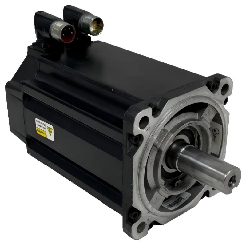
Allen-Bradley MPL-B980E-MJ74AA Servo Motor: Detailed Product Description, Technical Parameters, Applications, Advantages, and Related Models
1. Product Overview
The Allen-Bradley MPL-B980E-MJ74AA is a low-inertia, brushless AC rotary servo motor designed for industrial automation and precision motion-control applications. It belongs to the MPL family within the MP-Series range and is intended for machinery that requires controlled rotation, repeatable positioning, coordinated movement, and dependable operation over repeated production cycles.
This model is configured for the 460 V AC class and features a nominal 300 mm frame size, a 203.2 mm magnet stack, a keyed shaft extension, and a multi-turn high-resolution absolute feedback encoder. It also has a right-angle SpeedTEC DIN connector that can be rotated through 180 degrees, together with a 24 V DC holding brake.
The brake is the main configuration difference between this model and the closely related MPL-B980E-MJ72AA. The MJ74AA version includes a motor-mounted brake, while the MJ72AA version does not. This distinction matters when a machine needs to hold an axis in position after motor power is removed.
The motor is designed to work as part of a compatible servo system, including a motion controller, servo drive, feedback and power cables, and a suitable mechanical load. Its final performance depends on correct sizing, drive compatibility, installation, and servo tuning.
2. Product Identification
|
Parameter |
Specification |
|---|---|
|
Model |
|
|
Brand |
Allen-Bradley |
|
Product family |
MP-Series |
|
Motor series |
MPL low-inertia brushless servo motors |
|
Product type |
AC rotary servo motor |
|
Motor construction |
Brushless permanent-magnet servo motor |
|
Voltage class |
460 V AC |
|
Frame designation |
Size 9 |
|
Nominal frame dimension |
300 mm (11.81 in.) |
|
Magnet stack length |
203.2 mm (8.0 in.) |
|
Catalog speed designation |
E configuration; catalog descriptions commonly list 2250 RPM, while detailed performance data should be checked for the applicable speed rating |
|
Feedback |
Multi-turn, high-resolution absolute encoder |
|
Shaft |
Keyed shaft extension |
|
Connector |
SpeedTEC DIN, right-angle, rotatable 180° |
|
Brake |
24 V DC motor-mounted holding brake |
|
Mounting |
IEC metric |
|
Mounting holes |
Free mounting holes, Type FF |
|
Shaft seal |
Standard configuration generally listed without a shaft seal; verify the exact unit |
|
Overall dimensions |
Confirm from the mechanical drawing for the exact configuration |
|
Weight (kg) |
Approximately 94.5 kg as a published technical-data reference; verify net weight and brake configuration before installation or shipping |
|
Intended applications |
Industrial automation, positioning, indexing, material handling, and coordinated motion |
Note about dimensions and weight: The 300 mm frame designation and 203.2 mm stack length are useful identification dimensions, but they do not describe the complete outside dimensions of the assembled motor. The holding-brake version may also have a different overall axial length from the brake-free version.
For mechanical design, confirm the flange dimensions, mounting-hole pattern, shaft projection, total length, connector clearance, and weight from the drawing for the exact catalog number. The stated weight is a planning reference and should not replace confirmation of the supplied unit’s net weight.
3. Detailed Technical Parameters
|
Parameter |
Description |
|---|---|
|
Model |
MPL-B980E-MJ74AA |
|
Rated voltage class |
460 V AC |
|
Motor category |
Brushless AC rotary servo |
|
Motor family |
MPL low-inertia |
|
Frame size |
9 |
|
Nominal frame dimension |
300 mm |
|
Magnet stack length |
203.2 mm |
|
Speed configuration |
E |
|
Speed reference |
Catalog descriptions commonly identify 2250 RPM; consult the exact performance table for rated and maximum operating speed |
|
Feedback device |
Multi-turn high-resolution absolute encoder |
|
Shaft type |
Keyed shaft extension |
|
Connector type |
SpeedTEC DIN |
|
Connector orientation |
Right-angle, rotatable through 180° |
|
Brake voltage |
24 V DC |
|
Brake type |
Motor-mounted holding brake |
|
Mounting standard |
IEC metric |
|
Mounting-hole arrangement |
Type FF |
|
Rated output power |
Confirm from the motor performance table for the applicable operating conditions |
|
Continuous stall torque |
Confirm from the applicable motor performance table |
|
Peak torque |
Confirm from the applicable motor performance table |
|
Rotor inertia |
Confirm from the applicable motor performance table |
|
Overall length |
Obtain from the mechanical drawing; brake configuration affects axial dimensions |
|
Width and height |
Obtain from the mechanical drawing |
|
Weight (kg) |
Approximately 94.5 kg as a technical-data reference; confirm the exact unit and whether the figure is net or shipping weight |
|
Environmental protection |
Verify the protection rating and environmental limitations for the exact unit |
|
Drive compatibility |
Confirm the supported motor and feedback configuration, voltage class, current ratings, and drive parameters |
3.1 Speed and performance clarification
The letter E identifies the speed configuration within the model family, but a catalog speed designation should not be treated as a complete description of the motor’s operating limits. Published product descriptions and detailed motor performance tables may use different speed figures for catalog identification, rated operation, and maximum speed.
For engineering calculations, use the performance data applicable to the exact motor and drive combination. Continuous torque, peak torque, allowable speed, thermal limits, and duty cycle must be considered together.
3.2 Holding-brake configuration
The MJ74AA configuration includes a 24 V DC holding brake. This brake is intended to help hold the motor shaft when the brake is engaged, commonly when motor power is removed or the system is placed into a designated holding state.
A holding brake should not automatically be treated as a service brake for repeatedly stopping a moving load. Its permitted stopping duty, engagement conditions, holding torque, and control requirements must be checked against the relevant specifications.
For vertical axes or suspended loads, the brake must be included in the machine’s complete safety design. Depending on the application, additional mechanical restraints, counterbalancing, or other protective measures may be required.
4. Product Introduction and Operating Principle
The MPL-B980E-MJ74AA converts electrical energy into controlled rotary motion. In a typical servo system, the motion controller sends a movement command to a compatible servo drive. The drive regulates the motor’s electrical input, and the feedback encoder reports shaft position so the control system can monitor and adjust the movement.
This closed-loop arrangement is useful when machinery must move to defined positions, maintain a commanded speed, or coordinate motion with other axes. It also allows the control system to respond to changes in load and movement error within the capabilities of the motor, drive, and mechanical system.
The motor’s low-inertia design is intended for applications involving repeated acceleration, deceleration, and direction changes. Its absolute feedback capability can be valuable in equipment that needs multi-turn shaft-position information. The motor-mounted brake adds a holding function when the axis design requires it.
The motor is not a stand-alone motion-control system. Its performance depends on the selected drive, control software, electrical connections, load inertia, mechanical transmission, mounting stiffness, and tuning. A motor with suitable nominal speed may still be unsuitable if its continuous torque, peak torque, or thermal capacity does not meet the actual duty cycle.
5. Main Product Features
5.1 Low-inertia brushless construction
The MPL motor design is intended to provide responsive motion in automated equipment. Low rotor inertia can make it easier for a correctly sized system to accelerate and decelerate, particularly when the machine frequently changes position or speed.
The benefit depends on the inertia of the complete moving system. A large load, high transmission ratio, flexible coupling, or excessive mechanical friction can substantially affect the result.
5.2 Multi-turn absolute feedback
The multi-turn high-resolution encoder provides detailed rotational position information to the compatible servo drive. This is useful for systems that need to track shaft position across multiple revolutions.
Correct operation requires a compatible feedback interface, suitable cabling, and proper drive configuration. Absolute feedback does not eliminate the need for commissioning, reference checks, or application-specific position validation.
5.3 Integrated 24 V DC holding brake
The brake is an important feature of the MJ74AA version. It can help keep the shaft stationary when the brake is engaged, which may be useful in vertical positioning mechanisms and other applications where an axis must resist movement at standstill.
The brake must be controlled according to its specified electrical and mechanical limits. The design should account for brake-release timing, brake-engagement timing, holding requirements, and the consequences of power loss.
5.4 Keyed shaft extension
The keyed shaft is intended for use with compatible couplings, pulleys, gears, and other transmission components. A correct mechanical connection helps transmit torque while maintaining alignment between the motor and driven load.
The shaft diameter, key dimensions, usable shaft length, and allowable radial and axial loads should be verified before choosing a coupling or replacing an existing motor.
5.5 Rotatable right-angle connector
The right-angle SpeedTEC DIN connector can help accommodate different machine layouts. Its 180-degree rotation capability provides flexibility when routing motor cables through a crowded enclosure or along a compact machine frame.
During installation, allow adequate cable clearance and bend radius. The connector should not be forced into a position that strains the cable or interferes with maintenance access.
5.6 Metric mounting arrangement
The IEC metric mounting arrangement can be useful when integrating the motor into equipment designed around metric dimensions. Nevertheless, the mounting designation alone does not confirm that the motor will fit an existing bracket or gearbox.
Check the full mechanical drawing, including mounting holes, flange dimensions, shaft geometry, total length, and the extra axial space required by the brake configuration.
6. Product Applications

6.1 Packaging and filling equipment
Packaging machinery often requires repeated indexing, feeding, sealing, cutting, and transfer movements. A servo motor can provide controlled motion for these operations, while encoder feedback helps the controller monitor shaft position.
The holding brake may be useful where an axis needs to remain stationary during a defined machine state. The actual motor selection must still be based on the packaging cycle, load, acceleration, and continuous operating requirements.

6.2 Automated assembly lines
Servo motors are used to position fixtures, move components, operate indexing tables, and coordinate multiple machine axes. Absolute feedback can support position tracking where the control system requires multi-turn information.
The final positioning accuracy depends on the whole mechanical system, including backlash, coupling stiffness, fixture rigidity, and control-loop tuning.

6.3 Machine tools and precision machinery
Servo motors can be used in feed systems, positioning mechanisms, and coordinated rotary applications. The correct model depends on the required speed, torque, mechanical loads, and operating duty.
The motor should be selected from verified performance data rather than from its model designation alone.

6.4 Material handling and positioning systems
The motor may be considered for transfer mechanisms, positioning tables, driven rollers, and certain lift or handling axes. The holding brake can be relevant when the mechanical design requires the motor shaft to resist movement at standstill.
For any vertical or gravity-loaded axis, verify the complete brake and safety arrangement rather than relying on the motor brake alone.

6.5 Printing and converting machinery
Printing and converting systems may use servo motors to control feed rollers, rotary mechanisms, and coordinated axes. Feedback-based control helps synchronize motion, while the brake may assist with holding where the application design calls for it.
Roller diameter, material tension, speed profile, and synchronization requirements should be included in the motor-sizing calculations.
Additional application areas
Other possible applications include automated inspection equipment, electronic component handling, specialized production machinery, and compatible retrofit installations. Suitability depends on the required torque, speed, load inertia, environmental conditions, and the drive system.
The motor should not be assumed suitable for every industrial environment. Washdown, hazardous locations, high contamination, unusually high ambient temperatures, or other special conditions require specific verification.
7. Product Advantages
|
Advantage |
Practical value |
Selection consideration |
|---|---|---|
|
Low-inertia design |
Can support responsive acceleration and deceleration |
The load and drive must be correctly sized |
|
Multi-turn absolute feedback |
Provides shaft-position information across multiple turns |
Confirm encoder and drive compatibility |
|
24 V DC holding brake |
Helps hold the shaft when the brake is engaged |
Verify holding requirements and brake limits |
|
Keyed shaft |
Provides a positive mechanical interface for compatible transmission components |
Check shaft and key dimensions |
|
Rotatable right-angle connector |
Offers flexibility in cable routing |
Maintain clearance and the specified bend radius |
|
Metric mounting |
Can simplify integration into metric machine designs |
Confirm the exact mounting drawing |
|
Industrial servo construction |
Supports closed-loop motion-control applications |
Follow the specified electrical and environmental limits |
|
Related MPL configurations |
Provides options for comparing speed and brake arrangements |
Similar catalog numbers are not automatically interchangeable |
7.1 Controlled motion
Feedback-based servo control helps regulate movement according to the command from the controller. This is important for repetitive positioning, indexing, and coordinated machine operations.
Achievable accuracy is influenced by mechanical backlash, vibration, load variation, shaft compliance, and servo tuning. Encoder resolution is only one part of the overall accuracy calculation.
7.2 Holding capability
The motor-mounted brake is a practical distinction between the MJ74AA model and a similar brake-free configuration. It may help prevent unwanted shaft movement when the brake is properly engaged and the application falls within its specified holding capability.
A brake does not eliminate the need for a safe machine design. In particular, a suspended load may require independent protection against falling if the brake or its control circuit fails.
7.3 Integration flexibility
The keyed shaft, metric mounting arrangement, and rotatable connector provide several useful installation features. These can help when laying out a new machine or evaluating a replacement for an existing installation.
Mechanical compatibility should still be confirmed from drawings. A small difference in shaft projection or overall length can create substantial installation problems in a tightly packaged machine.
7.4 Potential for equipment standardization
Where a production line already uses compatible MPL motors and drives, selecting another motor from the same family can simplify the comparison process. Shared product-family characteristics can help narrow the options.
However, the complete model number matters. Differences in speed configuration, stack length, feedback, connector, and brake arrangement can change both the motor’s behavior and its physical installation requirements.
8. Brand and Product Series
|
Item |
Description |
|---|---|
|
Brand |
Allen-Bradley |
|
Product family |
MP-Series |
|
Motor series |
MPL |
|
Series type |
Low-inertia brushless servo motors |
|
Motor category |
Industrial AC rotary servo motor |
|
Control method |
Closed-loop servo control with encoder feedback |
|
Typical system components |
Motion controller, compatible servo drive, motor power cable, feedback cable, and mechanical load |
|
Brake configuration |
24 V DC holding brake |
|
Shaft configuration |
Keyed shaft extension |
|
Mounting arrangement |
IEC metric |
|
Main selection factors |
Voltage, speed, torque, feedback, brake, dimensions, weight, and drive compatibility |
The MPL series is intended for industrial machinery that needs controlled rotary motion and responsive dynamic behavior. Different catalog configurations allow users to compare frame size, stack length, speed designation, feedback type, connector arrangement, and brake option.
When replacing an existing motor, the series name is only a starting point. Confirm the entire catalog number and the specifications of the connected drive before ordering a replacement.
9. Model Number Interpretation
The following table explains the principal configuration elements in MPL-B980E-MJ74AA at a practical level. The complete catalog-code definitions and the applicable product revision should be checked for formal engineering use.
|
Code element |
General interpretation |
|---|---|
|
MPL |
MPL low-inertia brushless servo motor family |
|
B |
460 V class configuration |
|
9 |
Frame-size designation associated with a nominal 300 mm frame dimension |
|
80 |
Magnet stack designation associated with 203.2 mm |
|
E |
Speed configuration designation |
|
M |
Multi-turn high-resolution absolute feedback configuration |
|
J |
Keyed shaft extension |
|
7 |
SpeedTEC DIN connector, right-angle and rotatable configuration |
|
4 |
24 V DC holding-brake configuration |
|
AA |
Additional catalog configuration code; confirm the detailed definition for the exact revision |
The model number is useful for identifying the motor configuration, but it does not contain all the information required for a complete engineering assessment. Detailed performance data is needed for torque, power, speed limits, rotor inertia, thermal behavior, and permissible shaft loads.
10. Five Related Models in the MPL Series
The following models are useful comparison candidates because they belong to the same general low-inertia servo family or share a closely related configuration. The most appropriate alternative depends on whether the application needs a different speed, a shorter magnet stack, or a different brake arrangement.
The dimensions below identify the nominal frame and stack where applicable. The overall dimensions and exact mass should be confirmed for the selected catalog number, particularly when a holding brake is fitted.
|
Model |
Voltage class |
Speed designation |
Frame / stack |
Feedback |
Brake |
Overall dimensions |
Weight (kg) |
|---|---|---|---|---|---|---|---|
|
MPL-B980E-MJ72AA |
460 V AC |
E; catalog descriptions commonly list 2250 RPM |
300 mm / 203.2 mm |
Multi-turn absolute |
No brake |
Confirm exact drawing |
Verify exact unit |
|
MPL-B980D-MJ74AA |
460 V AC |
D; 2000 RPM |
300 mm / 203.2 mm |
Multi-turn absolute |
24 V DC |
Confirm exact drawing |
Verify exact unit |
|
MPL-B980C-MJ74AA |
460 V AC |
C; 1500 RPM |
300 mm / 203.2 mm |
Multi-turn absolute |
24 V DC |
Confirm exact drawing |
Verify exact unit |
|
MPL-B980B-MJ74AA |
460 V AC |
B; 1000 RPM |
300 mm / 203.2 mm |
Multi-turn absolute |
24 V DC |
Confirm exact drawing |
Verify exact unit |
|
MPL-B960D-MJ74AA |
460 V AC |
D; 2000 RPM |
300 mm / 152.4 mm |
Multi-turn absolute |
24 V DC |
Confirm exact drawing |
Verify exact unit |
10.1 MPL-B980E-MJ72AA
This model shares the same general B980E configuration as the target product but does not include a holding brake. It may be suitable for a horizontal axis or another application where an independent mechanical arrangement handles holding.
The main reason to consider it is to compare the same general motor configuration with and without a brake. It should not be selected for a gravity-loaded axis without checking the consequences of removing the motor-mounted holding function.
10.2 MPL-B980D-MJ74AA
This model uses the D speed designation and includes a holding brake. It may be worth considering when the application needs a similar frame and stack but has a lower speed requirement.
Before substituting it for the E configuration, check the required speed range, continuous torque, peak torque, acceleration profile, and motor-drive combination. The lower speed designation does not by itself guarantee that the model will deliver the required torque under every operating condition.
10.3 MPL-B980C-MJ74AA
This is another brake-equipped B980 configuration, associated with the C speed designation. It can be considered for machinery operating at a lower nominal speed, provided the motor’s performance data matches the load.
Its similar frame and stack dimensions can make it a useful candidate for comparison during an initial selection. However, shaft loads, torque requirements, cable compatibility, and the full mounting drawing still need to be checked.
10.4 MPL-B980B-MJ74AA
This model is associated with the B speed designation and has a holding brake. It may be suitable for applications where a lower-speed configuration is appropriate.
The motor should be evaluated against the actual speed and torque requirements, including the time needed to accelerate and decelerate the load. A lower nominal speed does not automatically make a motor more suitable for a high-torque application.
10.5 MPL-B960D-MJ74AA
The B960D configuration has a shorter magnet stack than the B980 family and is associated with a 2000 RPM speed designation. It is a potential comparison candidate when the required torque and installation space differ from those of the B980E.
Because the stack length differs, the performance and physical arrangement should not be assumed to match the B980E. Confirm the rated torque, peak torque, output power, overall length, brake clearance, and weight before considering it a replacement.
11. Five Additional Allen-Bradley Models to Consider
The following list expands the comparison to other motor configurations and servo-drive products in the same broader industrial motion-control portfolio. These products serve different roles and are not all direct replacements for the MPL-B980E-MJ74AA.
|
Model |
Product type |
Main configuration or role |
Voltage / speed reference |
Dimensions |
Weight (kg) |
|---|---|---|---|---|---|
|
MPL-B880D-SJ72AA |
Servo motor |
MPL low-inertia; different frame and single-turn feedback configuration |
460 V class; 2000 RPM designation |
Frame 265 mm; stack 203.2 mm; overall dimensions to be confirmed |
Verify exact unit |
|
MPL-B960C-MJ72AA |
Servo motor |
MPL low-inertia; shorter stack, multi-turn feedback, no brake |
460 V class; 1500 RPM |
Frame 300 mm; stack 152.4 mm; overall dimensions to be confirmed |
Verify exact unit |
|
MPM-B1653E-MJ72AA |
Servo motor |
MPM medium-inertia family; alternative inertia characteristics |
460 V class; E speed configuration |
Obtain exact mechanical drawing |
Verify exact unit |
|
Kinetix 5500 |
Servo-drive family |
Drive platform for compatible servo motion systems |
Depends on exact drive catalog number |
Depends on exact drive model |
Depends on exact drive model |
|
Kinetix 5700 |
Servo-drive family |
Modular drive platform for larger or multi-axis systems |
Depends on exact drive catalog number |
Depends on exact drive model |
Depends on exact drive model |
11.1 MPL-B880D-SJ72AA
This is a related low-inertia motor configuration with a different frame designation and feedback-code configuration. It may be considered where the load and mounting arrangement permit a different frame size.
It should not be treated as a direct B980E replacement simply because it belongs to the MPL series. Confirm the shaft geometry, mounting pattern, torque, feedback compatibility, and overall dimensions before proceeding.
11.2 MPL-B960C-MJ72AA
This model has a shorter magnet stack than the B980 family and is associated with a 1500 RPM configuration. It may be useful when the machine’s required speed and torque are compatible with the B960 configuration.
The shorter stack affects the motor’s performance characteristics, so the exact torque and power ratings should be compared with the machine’s load profile. Its brake-free configuration also differs from the target model.
11.3 MPM-B1653E-MJ72AA
The MPM series is associated with medium-inertia servo motors. This makes it a potential comparison option when the load inertia and dynamic requirements differ from those suited to the MPL low-inertia family.
The choice between MPL and MPM should be based on the complete motor-load system. Neither low inertia nor medium inertia is universally better; the appropriate design depends on the load, transmission, required acceleration, stability, torque, and speed.
11.4 Kinetix 5500
Kinetix 5500 is a servo-drive family rather than a motor model. It is included because a motor’s compatibility with the drive is essential to any replacement or system-upgrade project.
The exact drive catalog number is needed to confirm voltage class, continuous and peak current, supported feedback, control-system compatibility, dimensions, and weight. Do not assume that every drive in the family supports every MPL motor configuration.
11.5 Kinetix 5700
Kinetix 5700 is another servo-drive family for industrial motion-control systems. It may be relevant where a machine uses a multi-axis architecture or needs a different drive arrangement.
As with any drive selection, the exact model, motor compatibility, current requirements, feedback interface, power architecture, and control platform must be checked. A drive family name alone is not enough to confirm compatibility with the MPL-B980E-MJ74AA.
12. Model Selection: Which Alternative Is Most Suitable?
|
Application requirement |
Models worth comparing |
Main reason |
|---|---|---|
|
Keep the same general B980E motor configuration but remove the brake |
MPL-B980E-MJ72AA |
Similar configuration without a motor-mounted holding brake |
|
Keep a similar B980 frame and add a lower-speed configuration |
MPL-B980D-MJ74AA, MPL-B980C-MJ74AA |
Different speed designations with a brake-equipped configuration |
|
Compare a lower-speed B980 motor |
MPL-B980B-MJ74AA |
Alternative speed configuration for evaluation |
|
Consider a shorter magnet stack |
MPL-B960D-MJ74AA, MPL-B960C-MJ72AA |
Different stack length and associated performance characteristics |
|
Evaluate a different inertia family |
MPM-B1653E-MJ72AA |
Medium-inertia motor family for different load characteristics |
|
Evaluate a drive-platform change |
Kinetix 5500, Kinetix 5700 |
Drive-system alternatives, subject to motor and control compatibility |
For a direct replacement, the closest candidate is not necessarily the model with the most similar speed designation. The brake, encoder, connector, shaft, mounting dimensions, and drive compatibility must all match the application.
If the existing machine relies on the MJ74AA holding brake, changing to an MJ72AA motor changes the system’s holding arrangement. That difference should be treated as an engineering decision, not merely a catalog substitution.
13. Installation and Commissioning
Mechanical installation
Before mounting the motor, check the flange, bolt pattern, shaft diameter, keyway, shaft projection, overall length, and connector clearance. Confirm that the coupling or driven component is compatible with the shaft and that alignment tolerances are satisfied.
The brake-equipped version may require additional axial space. Use the mechanical drawing for the exact catalog number rather than assuming the brake-free version and brake-equipped version have the same total length.
Electrical connection
Use the correct motor power and feedback cables for the motor and drive. Confirm connector compatibility, grounding, cable routing, and the drive’s configuration requirements before applying power.
The holding brake requires the appropriate 24 V DC control arrangement. Verify the wiring and control sequence for brake release and engagement, and ensure that the system does not command motion while the brake remains engaged.
Feedback configuration
Confirm that the drive supports the motor’s multi-turn absolute feedback interface. Set the correct motor configuration and feedback parameters, then verify that the drive reports valid position information.
A feedback mismatch can prevent the drive from operating correctly or cause position-control faults. Check the exact motor and drive documentation before reusing settings from another motor.
Servo tuning
Tune the system for the actual load inertia, transmission, acceleration, deceleration, and operating speed. Excessively aggressive settings can produce vibration or unstable motion, while overly conservative settings can reduce responsiveness.
When replacing an existing motor, do not assume that its previous control parameters are appropriate for a motor with a different speed designation, stack length, feedback configuration, or inertia.
Brake operation and safety
Verify the brake’s electrical supply, control logic, engagement timing, and holding requirements. For vertical axes, confirm that the machine has an appropriate strategy for preventing unexpected movement after loss of power.
The motor-mounted brake should not be assumed to provide every safety function required by the machine. The necessary safety measures depend on the load, mechanical design, risk assessment, and applicable machinery requirements.
14. Maintenance and Troubleshooting
|
Symptom |
Possible cause |
Recommended checks |
|---|---|---|
|
Motor does not start |
Drive fault, wiring problem, disabled command, or incompatible configuration |
Check drive status, enable signals, motor configuration, and power wiring |
|
Position error |
Feedback issue, tuning problem, or mechanical backlash |
Inspect feedback cabling, mechanical alignment, and control parameters |
|
Excessive heating |
Excessive load, high duty cycle, inadequate cooling, or incorrect tuning |
Compare the motion profile with the motor ratings and inspect cooling conditions |
|
Vibration or unusual noise |
Misalignment, loose mounting, coupling problems, or unstable control loop |
Check the mounting, shaft alignment, coupling, and tuning |
|
Axis moves when expected to hold |
Brake-control problem, incorrect wiring, or an inadequate holding arrangement |
Check the brake circuit and the complete load-holding design |
|
Brake fails to release |
Incorrect 24 V DC supply, wiring issue, or mechanical brake fault |
Verify the specified brake supply and inspect the brake circuit |
|
Feedback-related fault |
Damaged cable, connector issue, or incompatible drive configuration |
Inspect connectors and cables, then verify drive support |
|
Intermittent operation |
Loose connections, electrical interference, or thermal issues |
Inspect grounding, cable routing, connections, and operating temperature |
Maintenance should follow the applicable service instructions and the machine’s operating conditions. Do not dismantle or modify the motor or brake unless the procedure allows it and the work is performed by qualified personnel.
15. Final Product Summary
The Allen-Bradley MPL-B980E-MJ74AA is a low-inertia brushless AC servo motor in the MPL family of the MP-Series. Its principal configuration features are the 460 V AC class, 300 mm frame designation, 203.2 mm magnet stack, multi-turn high-resolution absolute feedback, keyed shaft extension, rotatable right-angle connector, and 24 V DC holding brake.
Its main strengths are the feedback-based motion-control capability, low-inertia motor design, practical installation features, and integrated holding-brake configuration. These features can be valuable in industrial machinery that needs controlled rotary movement and a defined holding function at standstill.
The most relevant related models are other B980 configurations with different speed or brake arrangements, followed by B960 and B880 variants where the application permits a different stack or frame size. MPM-series motors may also be worth evaluating where the load’s inertia characteristics differ.
Before purchasing or replacing the motor, confirm the following details:
-
The complete motor catalog number and revision.
-
The rated and maximum operating speed.
-
Continuous torque, peak torque, output power, and rotor inertia.
-
Compatibility with the existing servo drive and feedback interface.
-
The holding-brake requirements and control circuit.
-
The full mechanical drawing, including total length and mounting dimensions.
-
The verified net weight in kilograms.
-
The required motor power cable, feedback cable, and connector arrangement.
-
The environmental conditions and safety requirements of the machine.
These checks help ensure that the selected motor meets the actual mechanical and electrical requirements of the equipment, rather than relying on model-name similarity alone.