

ProductPRODUCT
Featured products
Contact Us
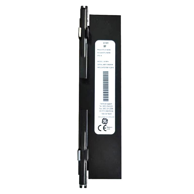
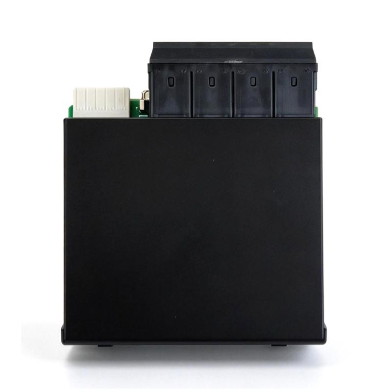
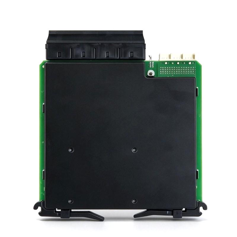
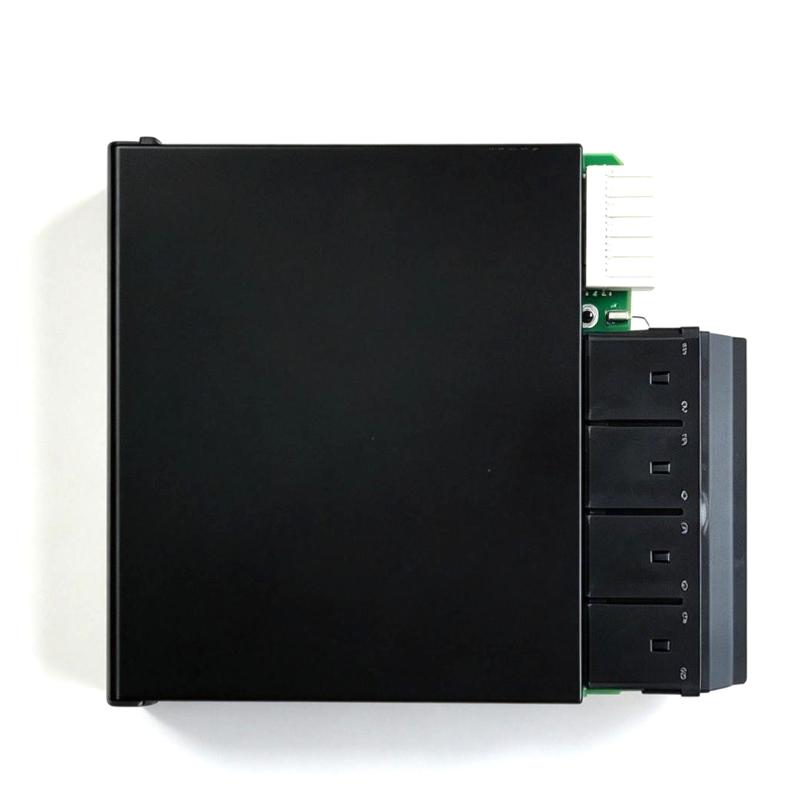
- GE
- UR 8FH
- Current Transformer/Voltage Transformer
- USA
- 120 × 30 × 100 mm
- 1.88 kg
- Xiamen, China
- New & In Stock
- T/T, PayPal, Western Union
- 1 Year
- 1-3 Working Days
- DHL, UPS, TNT, FedEx and EMS.
- 24-Hour Service
- COO
- 7
Our advantage

Global Logistics
We have a 10-year logistics and express cooperation agreement, so our products can be shipped to any place in the world.

Brand new and original
Our products are imported in bulk from the place of origin. Because of the cooperative relationship, our products are all original and 100% new.

24-hour service
We provide 7*24 hours service to our customers. We will be there whenever you need us.

Price advantage
All our products are priced very favorably because we have our own warehouse and supply.
| Company Information | |||
| [email protected] | |||
| Mobile | +8615980777398 | ||
| +8615980777398 | |||
| 15980777398 |
Product Overview
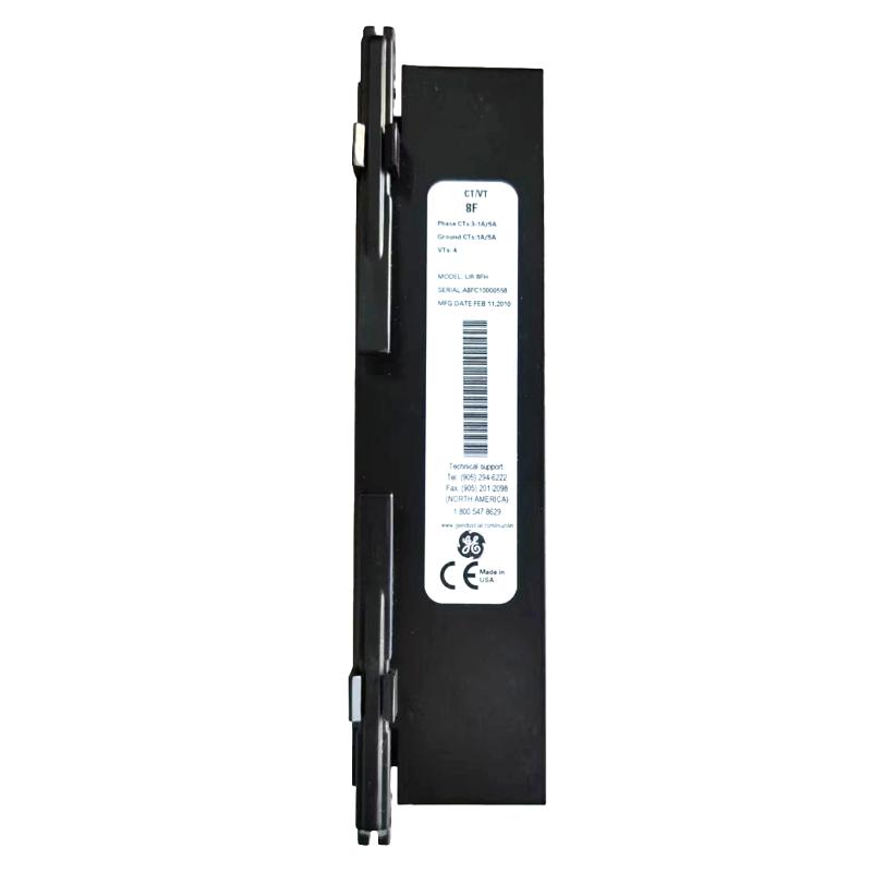
The GE UR 8FH is part of the Multilin Universal Relays (UR) product family, a platform used in power system protection, control, monitoring, and measurement applications. Current transformers (CTs) and voltage transformers (VTs) are fundamental to these systems because they provide electrical measurement signals that allow protective relays to evaluate operating conditions without connecting their internal measuring circuits directly to primary power conductors.
Within a protection system, CT and VT signals are used to represent primary circuit current and voltage at levels suitable for relay measurement inputs. These signals support functions such as overcurrent protection, voltage supervision, phase measurement, power system monitoring, and fault analysis, depending on the relay configuration and the associated protection scheme.
When working with the UR 8FH, the exact electrical role and connection arrangement should be confirmed against the equipment nameplate, terminal identification, and applicable GE Multilin documentation. The model designation identifies the product within the UR Series family, but specific input ratings, terminal assignments, and supported protection functions should not be assumed without the relevant product documentation.
For maintenance and replacement projects, correct identification is particularly important. A component that appears similar in the same relay family may have different electrical characteristics or connection requirements. Confirming the complete model number and its application helps prevent wiring errors and reduces the risk of using an unsuitable replacement in an existing protection panel.
Technical Specifications
| Parameter | Specification |
|---|---|
| Brand | GE |
| Model | UR 8FH |
| Product Family | Multilin UR Series |
| Product Type | Current Transformer/Voltage Transformer |
| Application | Electrical measurement and protection-system signal interfacing |
| Measurement Signal Sources | Current transformer and voltage transformer circuits, subject to the applicable configuration |
| System Role | Provides or supports current and voltage measurement signals for protection and monitoring |
| Typical Installation Environment | Electrical protection panel or compatible control cabinet |
| Integration | GE Multilin UR Series system; confirm the specific supported arrangement |
| Electrical Ratings | Verify against the product nameplate and applicable technical documentation |
| Input Configuration | Confirm from the applicable model documentation |
| Terminal Assignment | Follow the equipment terminal markings and manufacturer wiring information |
| Insulation and Safety Requirements | Confirm the ratings and installation requirements for the actual application |
| Dimensions | 120 × 30 × 100 mm |
| Weight | 1.88 kg |
Product Features
- Multilin UR Series Integration: Belongs to the GE Multilin UR product family, which is used in protection and monitoring arrangements for electrical power systems. Exact compatibility must be verified for the intended relay and hardware configuration.
- Current and Voltage Measurement Context: CT and VT circuits provide scaled electrical signals for protective relays. These signals allow the relay to assess electrical operating conditions without directly measuring primary circuit quantities at full system voltage and current.
- Support for Protection and Monitoring: Current and voltage measurements can contribute to protection logic, electrical supervision, event analysis, and operational monitoring when supported by the connected relay and its configured functions.
- Panel-Based Application: The component is intended for use within an electrical equipment installation. Panel layout, terminal access, wiring routes, and separation from unrelated circuits should be considered during installation and service.
- Model Identification for Maintenance: The complete UR 8FH designation should be recorded during inspection and replacement planning. Model identification helps maintenance personnel distinguish the component from other UR Series parts that may have different functions or electrical characteristics.
- Documentation-Dependent Configuration: Electrical ratings, supported connections, and application limits must be checked against the specific hardware documentation. This is especially important when integrating a component into an existing protection scheme.
- Replacement Planning: Before removing an installed unit, record its terminal wiring, associated relay model, and role in the measurement circuit. These records support controlled replacement and reduce the likelihood of incorrect reconnection.
Working Principle
The role of current and voltage transformer circuits in a protection system begins with the primary electrical network. A current transformer produces a secondary current that represents the current flowing through the primary conductor, while a voltage transformer provides a secondary voltage corresponding to the primary system voltage. The transformation ratios and secondary ratings depend on the selected transformers and the protection-system design.
The resulting secondary signals are routed to the designated measurement inputs in the protection equipment. The relay uses these signals to evaluate electrical quantities such as phase current and voltage, compare measured values with configured settings, and determine whether the monitored circuit is operating within its permitted limits. Where the relay supports the required functions, these measurements can contribute to fault detection, alarms, trip decisions, and event records.
The UR 8FH is identified as a Multilin UR Series Current Transformer/Voltage Transformer product. Its precise internal construction and signal-processing role cannot be established from the model designation alone. The actual operating path should therefore be confirmed from the applicable GE documentation and the wiring diagram for the installation rather than inferred from the product family name.
During commissioning, technicians should verify that the correct CT and VT circuits are connected to the intended terminals, that the configured ratios correspond to the installed transformers, and that the relay measurements are consistent with expected system conditions. Any discrepancy should be investigated before the protection scheme is placed into service.
Role in a GE Multilin UR Series Protection Architecture
| System Element | Role in the Architecture | Integration Considerations |
|---|---|---|
| Primary Electrical Network | Carries the current and voltage being monitored by the protection system | The monitored circuit and protection zone must be clearly identified |
| Current Transformers (CTs) | Convert primary current into a corresponding secondary measurement signal | Verify CT ratio, polarity, secondary rating, and circuit continuity |
| Voltage Transformers (VTs) | Provide secondary voltage signals representing the primary system voltage | Confirm voltage ratio, phase relationship, fusing, and circuit identification |
| GE UR 8FH | Identified as a Multilin UR Series Current Transformer/Voltage Transformer product | Confirm the exact hardware function, terminals, and supported configuration using the model-specific documentation |
| UR Series Protective Relay | Uses supported measurement inputs for protection, supervision, and monitoring functions | Confirm relay model, firmware or configuration requirements, input ratings, and enabled functions |
| Protection Settings | Define thresholds and operating logic for the configured protection functions | Settings must match the electrical system study and approved protection design |
| Trip and Alarm Circuits | Carry the relay’s output decisions to the associated alarm or circuit-breaker control circuits | Verify output assignments, interlocks, trip-circuit supervision, and end-to-end operation |
| Engineering and Maintenance Records | Preserve wiring diagrams, settings, model information, and test results | Keep records consistent with the installed hardware and approved revisions |
The UR 8FH should be considered within the complete measurement and protection arrangement rather than as an isolated component. Correct operation depends on the relationship between the transformer circuits, the installed relay hardware, configured measurement ratios, protection settings, and downstream alarm or trip circuits. Its precise position in this architecture must be confirmed against the applicable product documentation.
Industrial Applications
| Application | How CT/VT Measurement Supports the System | Practical Considerations |
|---|---|---|
| Electrical Substations | Supplies current and voltage information used by protection and monitoring equipment | Check instrument-transformer ratios, polarity, phase identification, and wiring records |
| Industrial Power Distribution | Supports supervision of feeders, switchgear, and distribution circuits | Ensure measurement circuits correspond to the correct feeder and protection zone |
| Motor Protection Systems | Current and voltage measurements can support protection functions available in the selected relay configuration | Confirm the relay’s supported motor-protection functions and applicable settings |
| Transformer Protection and Monitoring | Measurement signals may contribute to transformer electrical supervision and protection schemes | Verify the intended protection method and the compatibility of all measurement inputs |
| Generator Protection | Provides electrical measurements for functions supported by the associated protection equipment | Confirm generator-specific input requirements and protection settings |
| Circuit Breaker Protection | Measurement data can help the relay detect abnormal circuit conditions and initiate configured actions | Validate the complete trip path, including output logic and breaker control wiring |
| Industrial Process Plants | Supports electrical protection for plant distribution networks, drives, and critical loads | Coordinate the measurement circuit with plant drawings and equipment identification |
| Maintenance and Retrofit Projects | Provides a defined component reference when inspecting or replacing equipment in an existing panel | Verify the full model designation and terminal configuration before substitution |
The applications above describe common uses of CT/VT measurement within electrical protection systems. They do not establish that every listed protection function is implemented directly by the UR 8FH. Actual capabilities depend on the component’s documented role, the associated UR Series relay, and the installed system configuration.
Installation and Maintenance
- Verify the Complete Model Designation. Check the product label for the full UR 8FH designation before installation or replacement. Compare it with the bill of materials, panel drawings, and maintenance records to avoid confusing it with another UR Series component.
- Review the Applicable Documentation. Obtain the relevant GE Multilin documentation, terminal diagram, and equipment-specific wiring information. Do not determine terminal functions or electrical ratings solely from the model name.
- Apply Electrical Isolation Procedures. Before working on the installation, follow the site’s approved isolation, lockout/tagout, and verification procedures. CT and VT circuits may be associated with hazardous electrical energy even when the protection relay itself is de-energized.
- Handle CT Secondary Circuits Correctly. Never open an energized CT secondary circuit unless the system’s approved procedure and suitable shorting arrangements explicitly permit the work. An open CT secondary can produce dangerous voltage. Use the established site procedure before disconnecting or testing CT wiring.
- Inspect the Mounting Position. Confirm that the intended mounting location matches the equipment drawings and provides sufficient clearance for wiring, inspection, and service. Check that the component is secure and that its installation does not obstruct adjacent equipment.
- Check Wiring Identification. Before disconnecting an existing unit, label the conductors and record their terminal positions. Compare the field wiring with the latest approved schematic so that current and voltage measurement circuits can be traced correctly.
- Verify CT and VT Circuit Assignments. Confirm that each measurement circuit is connected to the intended input and phase. Check CT polarity, VT phase relationships, transformer ratios, and any specified grounding arrangements against the approved design.
- Inspect Terminals and Conductors. Look for loose connections, damaged insulation, corrosion, contamination, or signs of overheating. Use the conductor sizes, terminal preparation methods, and tightening requirements specified by the manufacturer for the actual hardware.
- Confirm Electrical Ratings. Check the component nameplate and applicable documentation for current, voltage, insulation, and other relevant ratings. Do not apply test signals or connect circuits until the suitability of the ratings has been established.
- Perform Commissioning Checks. After wiring verification, carry out the approved continuity, polarity, ratio, and measurement checks appropriate to the installation. Compare relay readings with expected values and investigate abnormal readings before enabling the protection scheme.
- Document Changes and Test Results. Record the installed model, wiring changes, test results, and any updates to drawings or configuration records. Clear documentation helps future technicians diagnose measurement errors and maintain the integrity of the protection system.
- Include the Component in Preventive Maintenance. During scheduled inspections, review the physical condition, terminal security, wiring integrity, and consistency of measurement readings. Follow the manufacturer’s service guidance and site maintenance intervals; do not assume that a component is functioning correctly based on appearance alone.
Compatible System Components
| Component | Function in the System | Compatibility Considerations |
|---|---|---|
| GE Multilin UR Series Protective Relay | Processes supported electrical measurements and executes configured protection logic | Confirm the specific relay model and the documented relationship with the UR 8FH |
| Current Transformer (CT) | Supplies a secondary current signal representing primary circuit current | Match ratio, secondary rating, accuracy requirements, polarity, and burden to the protection design |
| Voltage Transformer (VT) | Supplies a secondary voltage signal representing primary system voltage | Verify voltage ratio, phase relationship, insulation rating, and secondary protection |
| CT Shorting Terminal Block | Supports safe isolation and testing of CT secondary circuits when appropriately specified | Use a correctly rated device and follow the approved CT shorting procedure |
| VT Fuse or Protection Device | Provides specified protection for voltage measurement wiring | Select ratings and arrangements according to the approved schematic and manufacturer requirements |
| Relay Control Power Supply | Supplies operating power to the associated relay where required | Confirm the relay’s permitted supply range and wiring polarity |
| Trip Relay or Output Circuit | Transfers a protection decision to the circuit-breaker trip path or another control function | Verify contact ratings, output assignments, interlocks, and the complete trip circuit |
| Panel Terminal Blocks | Organize field wiring and measurement circuit connections | Check terminal ratings, wire identification, and segregation requirements |
| Engineering Configuration Tools | Support configuration and maintenance of compatible UR Series equipment where applicable | Confirm tool support for the specific relay model and configuration version |
| Protection Panel Wiring and Drawings | Define the intended electrical connections and protection architecture | Use the latest approved drawings and document any authorized changes |
The table identifies typical equipment used around CT/VT measurement and relay protection systems. It is not a manufacturer-certified compatibility list for the UR 8FH. Confirm direct compatibility, electrical ratings, and terminal assignments from the model-specific GE documentation before procurement or installation.
Recommended Related Models
| Model or Product Family | Product Role | Relationship to the UR 8FH |
|---|---|---|
| GE Multilin UR Series Protection Relays | Protection, control, and monitoring of electrical power systems | Relevant when identifying the relay equipment associated with the measurement circuit |
| GE Multilin UR Series Current Measurement Hardware | Supports current measurement within an applicable protection configuration | Consider only after confirming the specific model and its supported inputs |
| GE Multilin UR Series Voltage Measurement Hardware | Supports voltage measurement within an applicable protection configuration | Verify the required input type and the documented hardware arrangement |
| GE Multilin UR Series Feeder Protection Equipment | Provides feeder-related protection functions when supported by the selected relay | Relevant to distribution applications using CT/VT measurements |
| GE Multilin UR Series Motor Protection Equipment | Provides motor-related protection functions when supported by the selected relay | Relevant where current and voltage measurements are part of the motor protection scheme |
| GE Multilin UR Series Transformer Protection Equipment | Supports transformer protection functions in applicable configurations | Confirm the protection scheme and measurement requirements before selecting a related model |
These are related product categories and application families, not confirmed drop-in replacements for the UR 8FH. A suitable alternative must be identified by comparing the complete order code, documented function, electrical ratings, terminal arrangement, and system requirements. Do not substitute another UR Series model solely because it belongs to the same family.
Key Advantages
- Clear Model Identification: The UR 8FH designation provides a specific reference for equipment records, purchasing, and maintenance planning.
- Application Within a Established Protection Platform: Its association with the GE Multilin UR Series places it within a product family used for electrical protection and monitoring.
- Supports Measurement-Circuit Maintenance: Accurate identification and documentation help technicians trace CT/VT signal paths and investigate incorrect or inconsistent readings.
- Useful for Retrofit Planning: Recording the installed model and its associated wiring helps reduce uncertainty during panel upgrades and component replacement.
- Verification-Oriented Installation: Checking terminal assignments, transformer ratios, and ratings against the correct documentation supports safer commissioning and more dependable protection-system operation.
Technical FAQs
1. What is the GE UR 8FH?
The GE UR 8FH is identified as a Multilin UR Series Current Transformer/Voltage Transformer product. Its exact hardware function, electrical characteristics, and intended connection arrangement should be verified using the product nameplate and applicable GE documentation.
2. Can the UR 8FH be used with any GE Multilin UR Series relay?
Compatibility should not be assumed for every UR Series relay. Confirm the exact relay model, supported hardware configuration, electrical input requirements, and documented relationship with the UR 8FH before installation or replacement.
3. What should be checked before replacing the UR 8FH?
Verify the complete model designation, terminal markings, wiring diagram, CT and VT circuit assignments, electrical ratings, and the associated relay configuration. Follow approved isolation procedures, and take particular care with CT secondary circuits because opening an energized CT secondary can create dangerous voltage.
4. How can measurement problems associated with the UR 8FH installation be investigated?
Start by comparing the installed wiring with the approved schematic. Check terminal security, phase identification, CT polarity, VT phase relationships, transformer ratios, and relay measurement readings. If the readings remain abnormal, consult the applicable GE documentation and follow the site’s protection-system troubleshooting procedures.