

ProductPRODUCT
Featured products
Contact Us
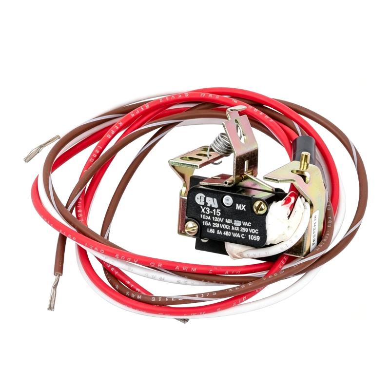
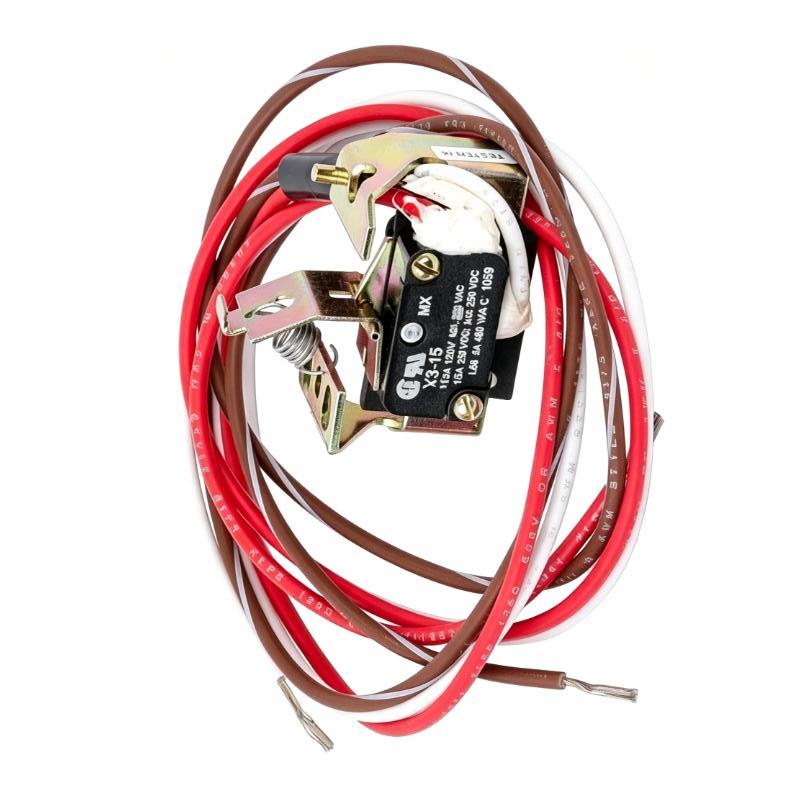
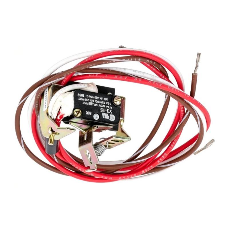
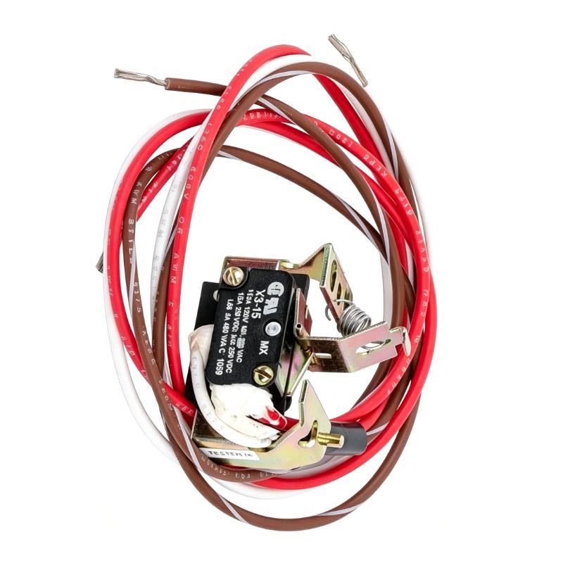
- GE
- TEDAS2AB2
- Auxiliary Switch
- USA
- 110 × 50 × 85 mm
- 0.3 kg
- Xiamen, China
- New & In Stock
- T/T, PayPal, Western Union
- 1 Year
- 1-3 Working Days
- DHL, UPS, TNT, FedEx and EMS.
- 24-Hour Service
- COO
- 9
Our advantage

Global Logistics
We have a 10-year logistics and express cooperation agreement, so our products can be shipped to any place in the world.

Brand new and original
Our products are imported in bulk from the place of origin. Because of the cooperative relationship, our products are all original and 100% new.

24-hour service
We provide 7*24 hours service to our customers. We will be there whenever you need us.

Price advantage
All our products are priced very favorably because we have our own warehouse and supply.
| Company Information | |||
| [email protected] | |||
| Mobile | +8615980777398 | ||
| +8615980777398 | |||
| 15980777398 |
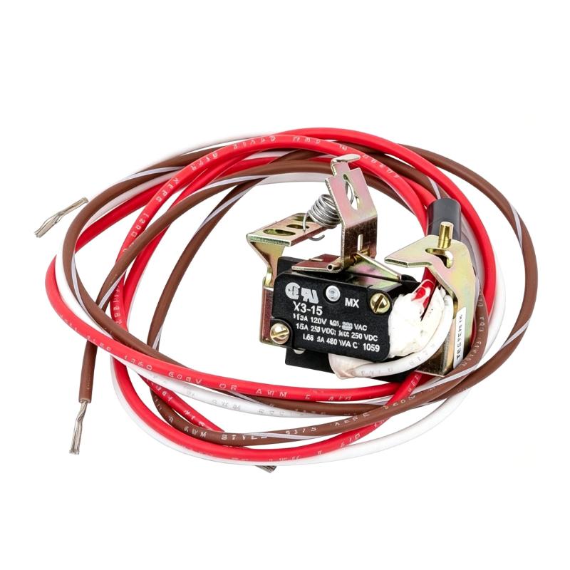
Product Overview
The GE TEDAS2AB2 Auxiliary Switch is an electrical accessory associated with compatible GE circuit breaker equipment. Auxiliary switches are used in low-voltage switching and control arrangements to provide an electrical indication of a circuit breaker’s operating position. This status information can be used by external control circuits, monitoring equipment, annunciation systems, and other devices that need to determine whether the associated breaker is open or closed.
In industrial electrical distribution systems, circuit breakers do more than interrupt current during abnormal conditions. Their operating status may also need to be communicated to a control panel, motor control circuit, building management system, or supervisory monitoring platform. An auxiliary switch provides a contact state that changes according to the associated breaker’s mechanical position, allowing external circuits to respond to the breaker status without relying solely on direct observation.
The TEDAS2AB2 is relevant to installations where a compatible breaker requires auxiliary contact functionality for status indication or control-circuit integration. During equipment selection, technicians should confirm the exact breaker family, accessory mounting arrangement, contact configuration, and electrical ratings specified by GE documentation. Auxiliary switches are not universally interchangeable, even when they appear similar or share a general accessory category.
For maintenance and replacement work, identifying the complete TEDAS2AB2 model number helps ensure that the selected accessory matches the existing breaker and the intended control-circuit application. Correct installation and wiring are important because an incorrectly configured auxiliary contact can cause inaccurate status indication, prevent a monitoring circuit from receiving the expected signal, or affect the operation of equipment that depends on breaker-position feedback.
Technical Specifications
| Parameter | Specification |
|---|---|
| Brand | GE |
| Model Number | TEDAS2AB2 |
| Product Type | Auxiliary Switch |
| Product Category | Circuit breaker accessory |
| Primary Function | Electrical indication of associated breaker operating status |
| Switching Mechanism | Mechanically associated with the compatible circuit breaker |
| Contact Operation | Changes contact state according to the associated breaker position, subject to the specific accessory configuration |
| External Interface | Auxiliary contact connection to an external control or monitoring circuit |
| Application | Breaker status indication and control-circuit integration |
| Compatible Equipment | Verify the exact circuit breaker family and accessory compatibility against GE documentation |
| Contact Configuration | Confirm from the product nameplate and applicable technical documentation |
| Contact Ratings | Refer to the manufacturer documentation for the specific model |
| Installation Environment | Electrical panel, switchboard, or approved circuit breaker installation |
| Maintenance Application | Inspection, replacement, and restoration of compatible auxiliary-switch functionality |
| Dimensions | 110 × 50 × 85 mm |
| Weight | 0.3 kg |
Product Features
- Breaker status indication: The TEDAS2AB2 is an auxiliary switch intended to provide an electrical indication associated with the operating position of compatible circuit breaker equipment. Its contact state can be used by an external circuit to determine whether the breaker has reached the relevant mechanical position.
- Integration with control circuits: Auxiliary contacts allow breaker status to be incorporated into electrical control schemes. Depending on the system design, the contact signal may be routed to a control panel, monitoring input, annunciator, or another circuit that requires breaker-position information.
- Mechanically associated switching: An auxiliary switch generally follows the movement of the associated breaker mechanism. This arrangement allows the external contact state to reflect the relevant breaker position without requiring a separate sensor to observe the breaker manually.
- Support for remote status monitoring: Where the breaker and control system are configured for remote monitoring, auxiliary contact information can be used to report breaker position to an operator interface or supervisory system. The exact indication available depends on the contact configuration and the connected circuit.
- Model-specific accessory identification: The TEDAS2AB2 designation provides a reference for identifying the intended switch accessory during procurement, installation, and maintenance. Checking the full model number helps prevent confusion with other auxiliary switches or breaker accessories.
- Electrical panel integration: An auxiliary switch can form part of a broader panel wiring arrangement that combines circuit protection, interlocking, status feedback, and operator indication. Its installation must follow the specified breaker accessory arrangement and applicable wiring requirements.
- Support for maintenance replacement: If an existing auxiliary switch becomes damaged or no longer provides the expected contact operation, a correctly matched replacement can help restore the required status feedback. Compatibility must be established before installation.
- Contact-based signal interface: The auxiliary switch provides a contact interface for external electrical circuits. The connected circuit must be designed for the contact configuration and ratings documented for the particular model.
- Improved equipment status visibility: When correctly installed and wired, auxiliary contacts help make breaker operating status available to control and monitoring equipment, reducing dependence on local visual inspection alone.
- Application-specific selection: Auxiliary switches may differ in mounting methods, contact arrangements, electrical ratings, and operating behavior. The TEDAS2AB2 should be selected according to the associated breaker and the requirements of the intended control circuit.
Working Principle
The GE TEDAS2AB2 operates as an auxiliary contact device associated with a compatible circuit breaker. When the breaker mechanism changes position, the associated mechanical movement actuates the auxiliary-switch mechanism. This movement changes the state of the switch contacts according to the contact arrangement provided by the specific accessory.
The contact state can then be used by an external circuit as a representation of the breaker position. For example, a monitoring circuit may use an auxiliary contact to indicate that a breaker has opened, while another control circuit may use a contact state as a permissive condition before allowing a subsequent operation. The actual logic depends on the circuit design and whether the selected contact is configured as normally open, normally closed, or another documented arrangement.
In a typical status-monitoring application, the auxiliary contact is wired to a compatible input on a control panel or monitoring device. When the breaker changes position, the contact changes state and the connected circuit detects the resulting electrical condition. The control system can then display the status, activate an indication, record an event, or evaluate the signal as part of an interlocking sequence.
The auxiliary switch does not replace the breaker’s primary protective mechanism. The circuit breaker remains responsible for switching and interrupting the power circuit within its specified operating capabilities. The auxiliary switch supplies a separate status contact for external electrical use; it should not be assumed to measure load current, detect faults independently, or provide a protective trip function unless the relevant documentation explicitly states otherwise.
During commissioning and troubleshooting, technicians should verify the accessory mounting, mechanical actuation, contact continuity, terminal identification, and external wiring. If the indicated status does not correspond to the breaker position, the investigation should include the switch mechanism, contact configuration, connected wiring, and receiving control input.
Role in a GE Circuit Breaker Control Architecture
| System Element | Relationship to the TEDAS2AB2 |
|---|---|
| Circuit Breaker Mechanism | Provides the mechanical movement associated with the auxiliary-switch operation. Compatibility with the specific breaker model must be verified. |
| Auxiliary Contact Mechanism | Changes electrical contact state according to the relevant breaker position and the documented switch configuration. |
| External Control Circuit | Uses the auxiliary contact as a status input or control condition when the application requires breaker-position information. |
| Electrical Distribution Panel | Provides the installation environment where the breaker and its associated accessory may be integrated into the panel’s wiring arrangement. |
| Remote Monitoring Equipment | Can receive auxiliary contact information for breaker-status indication, provided the monitoring input and wiring are compatible. |
| Operator Indication | Uses the contact signal to support local or remote indication of breaker position, according to the configured control scheme. |
| Interlocking Circuit | May use the auxiliary contact as one of the electrical conditions required to permit or inhibit a sequence of operations. The final behavior depends on the complete circuit design. |
| Alarm and Event Monitoring | Can use the contact state to support status alarms or event recording where the external system is configured for that purpose. |
| Maintenance and Troubleshooting | Provides a contact device that technicians can inspect and test when breaker status feedback is missing or incorrect. |
| Spare Parts Management | The TEDAS2AB2 model number helps maintenance personnel identify the intended replacement accessory and retain accurate equipment records. |
Industrial Applications
| Application | Role of the TEDAS2AB2 |
|---|---|
| Electrical Distribution Panels | Provides auxiliary contact functionality for compatible circuit breakers installed in industrial distribution equipment. The exact breaker compatibility must be verified before use. |
| Breaker Position Indication | Supplies an electrical contact state that can be used to indicate the associated breaker’s relevant operating position. The available indication depends on the switch configuration. |
| Remote Equipment Monitoring | Allows a compatible control or monitoring system to receive breaker-status information through an appropriately wired auxiliary contact circuit. |
| Motor Control Systems | May provide breaker-status feedback to a motor control circuit where the system design requires confirmation of breaker position before or after an operation. |
| Industrial Control Cabinets | Integrates breaker-position information into cabinet wiring for status feedback, operator indication, or other documented control functions. |
| Electrical Interlocking | Can form part of an interlocking circuit in which breaker status is used as one of the conditions governing an operating sequence. The complete interlocking logic must be engineered and verified separately. |
| Alarm and Annunciation Systems | Provides a contact signal that can be monitored by compatible equipment to indicate a specified breaker state or change of state. |
| Building Electrical Systems | May be used in compatible electrical panels where breaker-position feedback is required by a building monitoring or supervisory control arrangement. |
| Preventive Maintenance | Allows technicians to inspect and test the auxiliary contact as part of checking breaker accessories and their associated status circuits. |
| Circuit Breaker Accessory Replacement | Provides a model-specific replacement reference when an installed TEDAS2AB2 switch is damaged, worn, or fails to deliver the expected contact signal. |
| Legacy Electrical Equipment Support | Helps maintenance teams identify a specific accessory for an existing GE breaker installation when the original equipment configuration and compatibility have been confirmed. |
Installation and Maintenance
- Verify the accessory model. Confirm that the switch is identified as GE TEDAS2AB2 and that the full part number matches the required accessory. Do not select a replacement solely on the basis of appearance, dimensions, or a general auxiliary-switch description.
- Confirm circuit breaker compatibility. Check the associated breaker model and the manufacturer’s accessory documentation. Verify that the TEDAS2AB2 is approved for the intended breaker family and mounting arrangement before attempting installation.
- Review the electrical drawings. Examine the panel wiring diagram and control-circuit documentation to determine how the auxiliary contact is intended to be used. Identify the contact terminals, connected control inputs, and any status or interlocking logic associated with the switch.
- Isolate the equipment safely. Follow the facility’s approved electrical isolation and lockout/tagout procedures before installing or replacing the accessory. Confirm the required safe working condition and follow the applicable electrical safety requirements for the circuit breaker and its enclosure.
- Inspect the switch assembly. Examine the accessory housing, mounting features, terminals, and accessible contact areas for visible damage, contamination, deformation, or signs of overheating. Do not install a damaged unit without an appropriate technical assessment.
- Check the mounting arrangement. Verify the specified mounting location and orientation for the associated breaker. Confirm that the accessory fits the intended mounting position and does not interfere with the breaker mechanism, operating handle, covers, or adjacent components.
- Verify the contact configuration. Determine the documented contact arrangement and terminal identification before wiring. Do not assume that the contact is normally open or normally closed based only on the product name or the appearance of the accessory.
- Install the accessory correctly. Fit the switch according to the manufacturer’s installation instructions. Ensure that the mechanical operating interface engages as specified and that the accessory is securely mounted without forcing components or modifying the breaker assembly.
- Connect the control wiring. Connect conductors to the documented terminals according to the approved schematic. Use the specified conductor preparation and terminal-tightening requirements, and ensure that the connected circuit voltage and current are within the switch’s documented ratings.
- Check mechanical operation and contact continuity. With the equipment in the appropriate safe test condition, verify that the auxiliary contact changes state as expected when the associated breaker mechanism moves through its specified positions. Use the approved test method and avoid operating equipment in a way that compromises electrical safety.
- Verify the external status indication. After the wiring and mechanical checks are complete, confirm that the connected control input, indicator, or monitoring system reports the expected breaker status. If the indication is incorrect, check terminal assignments, contact configuration, accessory engagement, and the receiving circuit before returning the equipment to service.
- Document the installation and test results. Record the TEDAS2AB2 model, associated breaker identification, contact assignment, and maintenance findings. Update the panel drawings or maintenance records when required so future technicians can identify the installed accessory and understand its role in the status circuit.
Compatible System Components
| Component Category | Compatibility and Selection Considerations |
|---|---|
| GE Circuit Breakers | Confirm the exact breaker model and accessory compatibility in GE documentation. The TEDAS2AB2 should only be installed on equipment for which the accessory is specified. |
| Breaker Accessory Mounting Interface | Verify the mounting position, mechanical engagement, and installation method before fitting the auxiliary switch. |
| Auxiliary Contact Wiring | Select conductors and connection methods appropriate to the documented contact ratings and the intended control circuit. |
| Control Panels and Monitoring Inputs | Confirm that the receiving input is compatible with the contact arrangement and electrical characteristics of the auxiliary-switch circuit. |
| Breaker Status Indicators | May receive the contact signal for local or remote indication when the wiring and indicator circuit are designed for the specified contact operation. |
| Electrical Interlocking Circuits | The auxiliary contact may be used as part of an interlocking arrangement, provided the complete circuit is correctly designed and verified. |
| Alarm and Annunciation Equipment | Compatible monitoring inputs can use the contact state to indicate breaker status or a configured status change. |
| Panel Wiring Documentation | Wiring diagrams and terminal schedules are required to verify the contact assignment, connected circuit, and intended status logic. |
| Replacement Auxiliary Switches | Select by exact model and documented breaker compatibility. Similar appearance or a matching general function does not establish interchangeability. |
| Maintenance Test Equipment | Suitable electrical test instruments can be used to check contact continuity and switching behavior in accordance with the approved procedures. |
Recommended Related Models
| Model or Product Group | Product Description | Relationship |
|---|---|---|
| GE TEDAS2AB2 | Auxiliary Switch | Exact model for identification, replacement planning, and maintenance inventory. |
| GE Compatible Circuit Breakers | Circuit breaker equipment specified for use with the accessory | The associated breaker determines the mounting arrangement and application compatibility. Verify the exact breaker model before selection. |
| GE Auxiliary Switch Accessories | Auxiliary contact devices for compatible circuit breaker equipment | Related accessory category. Confirm contact configuration, electrical ratings, mounting arrangement, and breaker compatibility before choosing an alternative. |
| GE Circuit Breaker Status Accessories | Accessories used to provide operating-status information | Related at the functional level; the required device depends on whether the application needs auxiliary contacts or another form of breaker status indication. |
| GE Circuit Breaker Control Components | Components associated with breaker control and status circuits | May be used within the same panel architecture, subject to the electrical and mechanical requirements of the complete system. |
Key Advantages
- Breaker status feedback: Provides an auxiliary contact function that can communicate the associated breaker’s relevant operating position to an external circuit.
- Control-system integration: Supports the use of breaker-position information in compatible monitoring, indication, and control arrangements.
- Model-specific identification: The TEDAS2AB2 designation helps technicians and procurement teams identify the intended accessory for replacement work.
- Support for interlocking schemes: Can provide a contact state for an appropriately designed interlocking circuit when permitted by the application and equipment documentation.
- Maintenance accessibility: Allows the auxiliary contact and its wiring to be checked during troubleshooting of missing or incorrect breaker-status information.
- Improved status visibility: Helps make breaker operating position available to connected indication and monitoring equipment without depending entirely on local visual inspection.
- Equipment configuration continuity: Using the verified accessory model helps preserve the specified breaker accessory arrangement during maintenance and replacement.
- Traceable spare-parts management: Recording the full part number and associated breaker model supports accurate inventory control and future maintenance planning.
Technical FAQs
1. What is the GE TEDAS2AB2 Auxiliary Switch used for?
The GE TEDAS2AB2 is an auxiliary switch associated with compatible circuit breaker equipment. Its purpose is to provide a contact state that can be used by an external circuit to indicate the relevant breaker position. The exact breaker compatibility, contact arrangement, and electrical ratings should be confirmed from the manufacturer’s documentation.
2. Can the TEDAS2AB2 provide remote circuit breaker status indication?
An auxiliary contact can be wired to compatible monitoring or control equipment so that breaker status can be indicated remotely. Whether the TEDAS2AB2 supports the required indication depends on its documented contact configuration, the associated breaker, and the external control-circuit design.
3. Is the TEDAS2AB2 compatible with every GE circuit breaker?
No. Compatibility should not be assumed across all GE circuit breakers. Verify the exact breaker model, accessory mounting arrangement, contact configuration, and applicable product documentation before purchasing or installing the TEDAS2AB2.
4. What should be checked if the auxiliary switch does not report the correct breaker status?
Check the accessory’s mechanical engagement, mounting arrangement, contact configuration, terminal wiring, and external monitoring input. Contact continuity can be tested using an approved procedure in a safe electrical condition. If the contact changes state correctly but the control system still reports the wrong status, investigate the connected wiring and receiving input circuit.