

ProductPRODUCT
Featured products
Contact Us
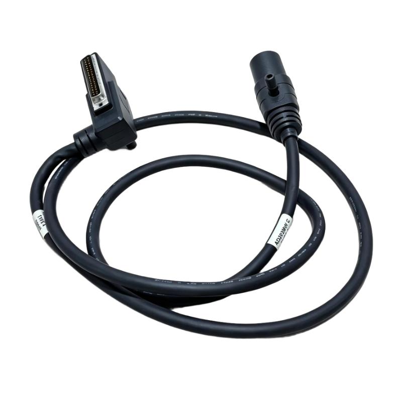
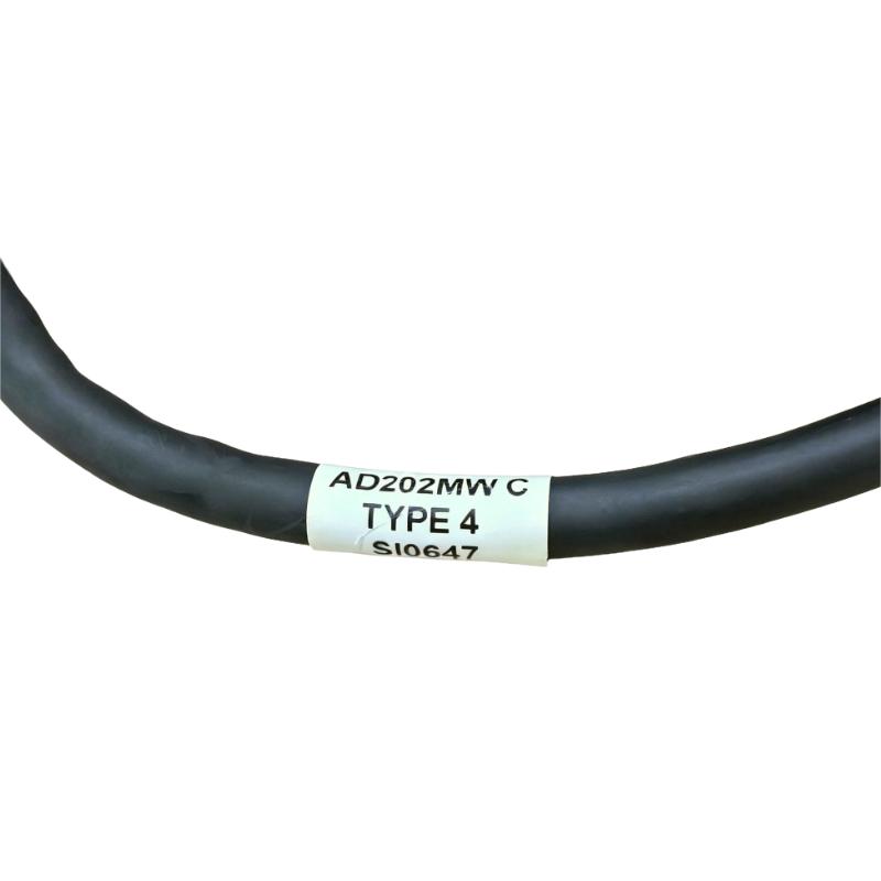
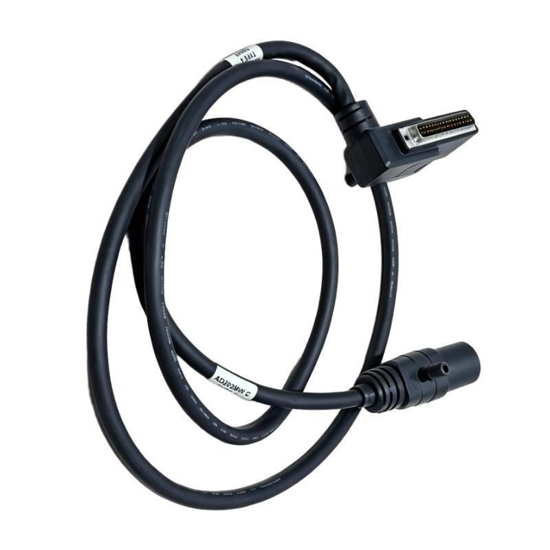
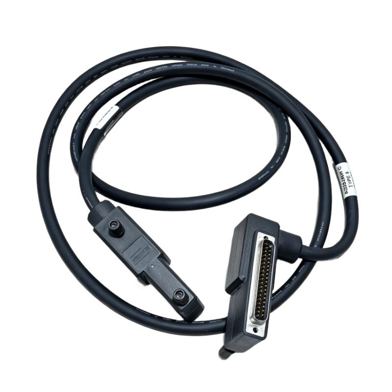
- Foxboro
- AD202MW
- Termination Cable
- USA
- 1.5 meters
- 3 kg
- Xiamen, China
- New & In Stock
- T/T, PayPal, Western Union
- 1 Year
- 1-3 Working Days
- DHL, UPS, TNT, FedEx and EMS.
- 24-Hour Service
- COO
- 7
Our advantage

Global Logistics
We have a 10-year logistics and express cooperation agreement, so our products can be shipped to any place in the world.

Brand new and original
Our products are imported in bulk from the place of origin. Because of the cooperative relationship, our products are all original and 100% new.

24-hour service
We provide 7*24 hours service to our customers. We will be there whenever you need us.

Price advantage
All our products are priced very favorably because we have our own warehouse and supply.
| Company Information | |||
| [email protected] | |||
| Mobile | +8615980777398 | ||
| +8615980777398 | |||
| 15980777398 |
Product Overview
The Foxboro AD202MW I/A Series 200 Type 4 Termination Cable is a dedicated cable assembly for interconnecting compatible hardware within Foxboro I/A Series 200 control-system installations. In distributed control system environments, termination cables form part of the physical interface between system components, allowing electrical connections to follow the intended cabinet wiring and equipment configuration.
The AD202MW is relevant to maintenance and system integration work where a specific termination cable is required to match the installed hardware. During cabinet assembly, technicians must identify the correct cable, confirm the corresponding connection points, and route the cable according to the control-system drawings. When an existing cable is damaged, has an unreliable connection, or must be removed during equipment replacement, the correct cable assembly helps restore the original wiring arrangement without introducing an unverified substitute.
For maintenance teams managing legacy Foxboro I/A Series installations, accurate part-number identification is particularly important. Cables can appear similar while differing in connector configuration, termination arrangement, or intended application. The AD202MW should therefore be selected by its full model designation and verified against the equipment documentation before installation.
Technical Specifications
| Parameter | Specification |
|---|---|
| Brand | Foxboro |
| Model Number | AD202MW |
| Product Series | I/A Series 200 |
| Product Type | Type 4 Termination Cable |
| Cable Length | 1.5 meters |
| Cable Assembly Type | Termination cable assembly |
| Primary Function | Electrical interconnection between compatible system components |
| Intended System | Foxboro I/A Series 200 control-system installations |
| Connection Arrangement | Must be verified against the specified equipment and wiring documentation |
| Connector Configuration | Confirm using the original cable assembly and applicable equipment documentation |
| Signal Assignment | Determined by the connected hardware and approved system wiring |
| Installation Location | Control cabinet or other approved equipment installation |
| Replacement Application | Replacement of a matching AD202MW cable assembly |
| Compatibility Verification | Confirm model, connector arrangement, termination type, and connected equipment |
| Shipping Weight | 3 kg |
Product Features
- Dedicated termination cable assembly: The AD202MW is identified as an I/A Series 200 Type 4 Termination Cable. Its application is associated with the physical interconnection requirements of compatible Foxboro control-system hardware.
- Model-specific identification: The full AD202MW designation supports accurate identification during purchasing, spare-parts inventory management, equipment maintenance, and replacement planning. Using the complete part number helps reduce the risk of selecting a cable based only on appearance.
- Defined cable length: The specified cable length supports installation planning and helps technicians determine whether the assembly is appropriate for the intended routing path. The actual route should be checked against cabinet layout, connector position, and the equipment installation requirements.
- Integration with existing control hardware: The cable can be considered for an existing I/A Series 200 installation when the applicable system documentation identifies the AD202MW as the required connection assembly. Compatibility should be established before connecting it to operating equipment.
- Support for maintenance replacement: When troubleshooting identifies a cable assembly as damaged or unsuitable for continued use, a correctly matched replacement can help restore the physical connection between the designated system components.
- Application-specific connection arrangement: Termination cables must match the interface requirements of the equipment they connect. The AD202MW should be checked for connector compatibility, termination configuration, and assigned connection points before use.
- Cabinet wiring organization: Correct cable selection and routing help maintain an orderly control cabinet. Appropriate routing also makes later inspection, troubleshooting, and equipment replacement easier for maintenance personnel.
- Support for legacy system maintenance: In installations where existing Foxboro I/A Series 200 hardware remains in service, retaining accurate cable identification and replacement records helps maintenance teams manage system-specific spare parts.
Working Principle
The Foxboro AD202MW operates as a physical electrical connection between designated compatible system interfaces. When correctly installed, the conductors within the cable provide the electrical path required by the connected equipment. The exact signals carried and the function of each connection depend on the hardware configuration and the wiring scheme specified for the installation.
The connection process begins with identifying the equipment interfaces that require interconnection. A technician checks the system drawings and the part number of the required cable, then confirms that the AD202MW matches the specified termination arrangement. The cable is routed between the designated connection points, and the connectors are seated and secured according to the applicable equipment instructions.
Once installed, the cable maintains the intended electrical path between the connected components. The equipment at either end performs its own assigned functions, such as control processing, signal handling, or interface operations. The cable itself does not execute control logic or independently process signals; its role is to provide the physical connection required for the configured system.
If the connection becomes intermittent or is interrupted, the resulting symptoms depend on the connected equipment and the signals involved. Troubleshooting should therefore include inspection of the cable and connectors, verification of the connection points, and review of system diagnostics. A replacement should be installed only after the correct cable configuration has been established.
Role in a Foxboro I/A Series 200 Control Architecture
| System Element | Relationship to the AD202MW |
|---|---|
| I/A Series 200 Control Hardware | The cable may provide an interconnection where the approved system configuration specifies the AD202MW. The exact connected devices must be confirmed from the relevant equipment documentation. |
| Termination Interface | The cable connects to the designated termination interface when its connector arrangement and application match the installation requirements. |
| Control Cabinet Wiring | It forms part of the cabinet’s physical wiring arrangement, helping establish the required connection path between the specified components. |
| Electrical Signal Path | The conductors carry the electrical signals assigned to the connected interfaces. Signal type and pin assignment must be verified from the system wiring information. |
| Equipment Integration | Correct cable selection helps maintain the intended relationship between connected hardware without substituting an unverified connection assembly. |
| Maintenance and Troubleshooting | The cable can be inspected as part of fault isolation when connection problems, physical damage, or suspected wiring interruptions occur. |
| Spare Parts Management | Recording the full AD202MW designation helps maintenance personnel identify the appropriate replacement and maintain traceability of installed parts. |
| System Restoration | When the cable is confirmed as the source of a connection problem, a correctly matched replacement can help restore the specified wiring arrangement. |
Industrial Applications
| Application | Role of the AD202MW |
|---|---|
| Distributed Control System Installations | Used as a termination cable in compatible Foxboro I/A Series 200 installations where the approved configuration calls for this model. The specific connection points should be confirmed from the system drawings. |
| Process Automation Control Cabinets | Supports the physical interconnection of designated control-system components inside an industrial cabinet. Correct cable identification and routing help maintain an organized wiring layout. |
| Industrial System Integration | Can be included in installation work when integrating compatible hardware into an existing I/A Series 200 architecture, provided the cable is specified for the required interface. |
| Control-System Maintenance | Provides a model-specific replacement option when an installed AD202MW cable requires inspection, removal, or replacement. |
| Fault Diagnosis and Repair | May be examined when technicians investigate intermittent connections, damaged cable jackets, loose connectors, or suspected interruptions in a connection path. |
| Legacy Equipment Support | Helps maintenance teams identify a specific termination cable for an established Foxboro installation where the original hardware configuration must be retained. |
| Control Cabinet Refurbishment | Can be used when restoring cabinet wiring, subject to confirmation of the required part number, termination arrangement, and connection assignment. |
| Spare Parts and Inventory Management | The model designation allows the cable to be recorded as a specific replacement item, reducing ambiguity when maintenance personnel request or issue spare assemblies. |
Installation and Maintenance
- Verify the cable part number. Before installation, check the product marking and confirm that the cable is identified as Foxboro AD202MW I/A Series 200 Type 4 Termination Cable. Do not select a substitute solely because its external appearance resembles the original assembly.
- Confirm the intended application. Review the equipment documentation and cabinet wiring drawings to establish whether the AD202MW is specified for the required connection. Verify the connected hardware and the intended termination points before removing or installing the cable.
- Follow site isolation procedures. Determine whether the associated equipment must be isolated or placed in a maintenance state before the connection is disturbed. Follow the plant’s approved procedures and the equipment manufacturer’s instructions to avoid unintended interruption of control functions.
- Inspect the cable assembly. Examine the cable jacket, accessible connector surfaces, strain-relief areas, and other visible sections for cuts, deformation, contamination, or signs of mechanical stress. If damage is found, assess whether the assembly is suitable for installation before connecting it to the system.
- Check connector compatibility. Compare the cable connectors with the intended equipment interfaces. Confirm the connector type and termination arrangement using the original assembly and applicable documentation. Do not force a connector into an interface or assume compatibility based on approximate dimensions.
- Identify the correct connection points. Use the approved wiring diagram, terminal schedule, or equipment instructions to confirm where each end of the cable must be connected. Where connection assignments are not clear, resolve the identification before proceeding rather than relying on assumptions.
- Plan the cable route. Check the intended path between the connected components and ensure that the cable can be installed without excessive tension. Keep the routing clear of sharp edges, moving mechanisms, hot surfaces, and other sources of physical damage.
- Avoid excessive bending or strain. Route the cable in accordance with the applicable equipment requirements. Do not crush the assembly under cabinet doors or covers, pull directly on the cable when disconnecting it, or apply tight bends that could damage the conductors or connectors.
- Secure the cable appropriately. Use suitable cable-management provisions to prevent the assembly from hanging under its own weight or interfering with adjacent wiring. Secure the route without applying excessive pressure to the cable jacket or connector bodies.
- Complete the connection carefully. Align each connector with its intended interface and secure it according to the equipment instructions. Check that both ends are fully seated and that the cable does not place mechanical load on the connected hardware.
- Verify the installation. After reconnection, follow the approved commissioning or maintenance procedure to confirm the expected equipment status and connection behavior. If an alarm or abnormal condition appears, review the wiring assignment, connector seating, and system diagnostics before returning the equipment to service.
- Record the maintenance activity. Document the AD202MW part number, the equipment or connection location, and the reason for installation or replacement. Record any visible damage or recurring connection issues so that future maintenance personnel can trace the cable history and identify potential recurring problems.
Compatible System Components
| Component Category | Compatibility and Selection Considerations |
|---|---|
| Foxboro I/A Series 200 Control Hardware | Confirm that the specific control hardware and installation documentation identify the AD202MW as the correct cable. The series designation alone does not establish compatibility with every device in the product family. |
| Termination Assemblies | Verify the required termination type and connector arrangement before pairing the cable with a termination assembly. The physical interface and wiring assignment must match the intended application. |
| Control-System Connection Interfaces | Identify the designated connection ports and verify the cable’s end connections against the approved wiring diagram. Do not infer pin assignments without documentation. |
| Cabinet Wiring Infrastructure | Check the cable route, mounting arrangement, and available space to ensure that the assembly can be installed without mechanical strain or interference with adjacent equipment. |
| Existing AD202MW Cable Assemblies | An existing cable can help confirm the required part number and connector arrangement. Inspect the original assembly and cross-check its identification against the equipment documentation before using it as the sole compatibility reference. |
| Replacement and Spare Cable Inventory | Record the complete model number and intended application. Keep the cable associated with the correct equipment or system location to reduce the risk of issuing an incompatible spare. |
| Associated Control-System Equipment | The exact equipment at each end of the cable must be established from the system configuration. The AD202MW should not be assigned to a specific module or interface without supporting documentation. |
Recommended Related Models
| Model or Product Group | Product Description | Relationship to AD202MW |
|---|---|---|
| Foxboro AD202MW | I/A Series 200 Type 4 Termination Cable | The exact model identified for this product entry and the primary reference for replacement and inventory matching. |
| Foxboro I/A Series 200 Control Modules | Control-system modules within the I/A Series 200 family | Potential associated hardware only where the installation documentation specifies the AD202MW connection. Verify the exact module and interface before selection. |
| Foxboro I/A Series 200 Termination Hardware | Termination assemblies used in compatible system configurations | May be associated with the cable’s termination function. The required assembly type and connector configuration must be confirmed from the system documentation. |
| Foxboro I/A Series 200 Interconnection Cables | System-specific cable assemblies | Related at the general product-category level. Another cable model should be selected only after its termination type, connector arrangement, and intended application have been verified. |
| Foxboro I/A Series 200 Replacement Parts | Model-specific maintenance and replacement components | Relevant to maintenance planning for installed I/A Series 200 systems. Each component must be matched to the equipment configuration rather than selected solely by product family. |
Key Advantages
- Specific model identification: The AD202MW designation gives maintenance and procurement teams a clear reference when identifying the required termination cable.
- Defined installation length: The specified cable length supports planning for the intended connection route and cabinet arrangement.
- Prepared cable assembly: A dedicated termination cable can simplify replacement when the original part number and connection configuration are known.
- Support for existing systems: The cable is relevant to compatible Foxboro I/A Series 200 installations where the system documentation calls for this specific model.
- Structured maintenance workflow: Model verification, connector inspection, and installation records help technicians manage cable replacement in an organized and traceable way.
- Reduced substitution risk: Using the exact model designation and checking the approved connection arrangement helps prevent selection based on appearance alone.
- Improved troubleshooting traceability: Recording the cable location and replacement history helps maintenance teams investigate recurring connection problems.
Technical FAQs
1. What is the Foxboro AD202MW I/A Series 200 Type 4 Termination Cable used for?
The Foxboro AD202MW is a Type 4 termination cable associated with Foxboro I/A Series 200 control-system installations. It provides a physical electrical connection between designated compatible interfaces when specified by the system configuration. The exact connected devices and signal assignments should be confirmed using the applicable equipment documentation and wiring diagrams.
2. What is the specified cable length of the AD202MW?
The specified cable length is 1.5 meters. Before installation, check the intended route between the connection points and confirm that the cable can reach without excessive tension, tight bends, or interference with adjacent equipment. The stated length should be retained as supplied in the product information.
3. How can the AD202MW be checked for compatibility with an existing Foxboro system?
Start by confirming the full AD202MW model designation and checking the control-system documentation for the required termination cable. Verify the connected equipment, connector arrangement, termination type, and assigned connection points. If the original cable is available, its markings and connector configuration can provide additional identification information, but compatibility should still be cross-checked against the approved system documentation.
4. What should be inspected when troubleshooting a suspected AD202MW cable problem?
Inspect the cable jacket and accessible connector areas for visible damage, deformation, contamination, or signs of strain. Check that both connectors are correctly seated and that the cable is connected to the designated interfaces. Review equipment diagnostics and the approved wiring diagram to distinguish a cable or connection problem from a fault in the connected hardware. Any replacement should use a cable confirmed to match the required model and termination arrangement.