

ProductPRODUCT
Featured products
Contact Us
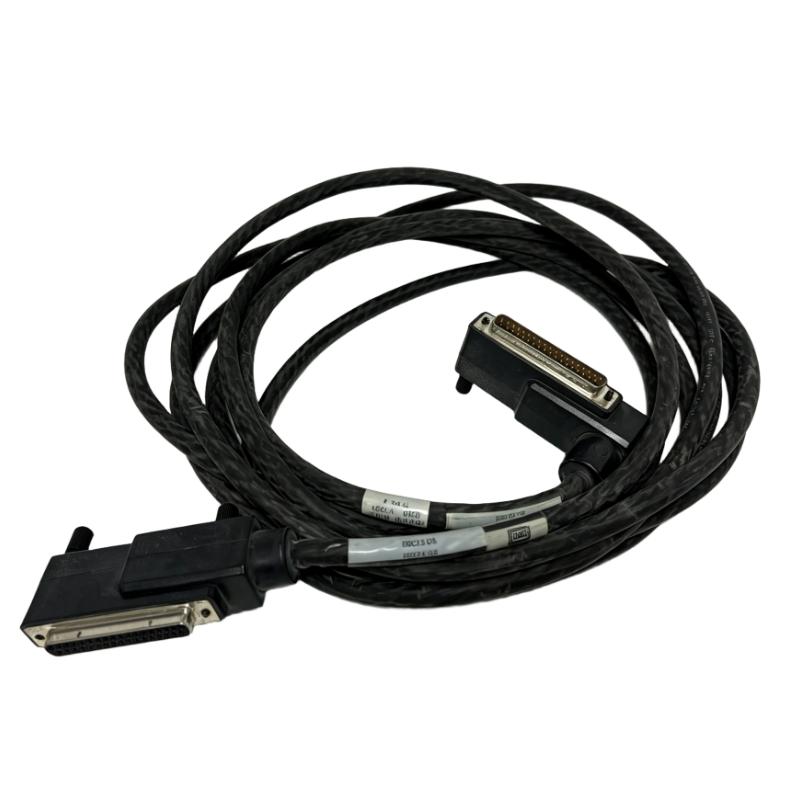
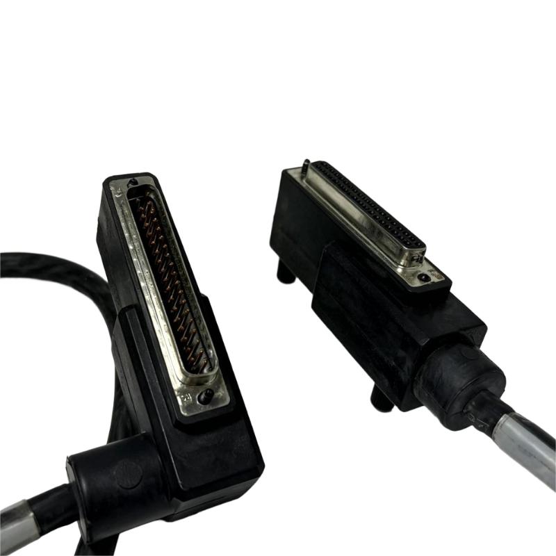
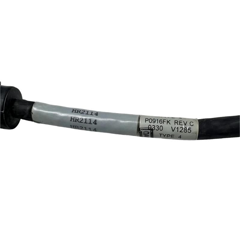
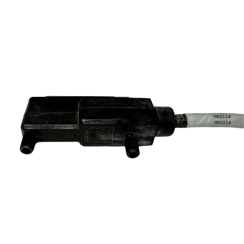
- Foxboro
- P0916FK
- Termination Cable
- USA
- 5 meters
- 3 kg
- Xiamen, China
- New & In Stock
- T/T, PayPal, Western Union
- 1 Year
- 1-3 Working Days
- DHL, UPS, TNT, FedEx and EMS.
- 24-Hour Service
- COO
- 8
Our advantage

Global Logistics
We have a 10-year logistics and express cooperation agreement, so our products can be shipped to any place in the world.

Brand new and original
Our products are imported in bulk from the place of origin. Because of the cooperative relationship, our products are all original and 100% new.

24-hour service
We provide 7*24 hours service to our customers. We will be there whenever you need us.

Price advantage
All our products are priced very favorably because we have our own warehouse and supply.
| Company Information | |||
| [email protected] | |||
| Mobile | +8615980777398 | ||
| +8615980777398 | |||
| 15980777398 |
Product Overview
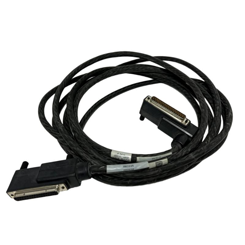
The Foxboro P0916FK I/A Series 200 Type 4 P/PVC Termination Cable is an industrial control-system cable associated with Foxboro I/A Series 200 equipment. Termination cables form part of the physical connection between control-system assemblies and their designated termination points, supporting the signal paths required by an installed automation system.
In a distributed control system (DCS), cable identification is important during equipment replacement and cabinet maintenance. For example, when a process plant experiences a cable fault in an existing control cabinet, maintenance personnel need to identify the installed cable reference and confirm its connection points before fitting a replacement. Using the correct model helps avoid confusion with other cables that may serve different assemblies or signal paths.
The P0916FK is relevant to maintenance and spare-parts planning for existing Foxboro I/A Series 200 installations. When preparing a replacement order, technicians should identify the connected hardware and check the existing wiring arrangement so that the replacement matches the intended installation.
For facilities operating legacy automation equipment, maintaining an accurate inventory of cable references can simplify troubleshooting, planned maintenance, and restoration work. Recording the cable model alongside its cabinet location and connection details also helps future technicians identify the correct component without repeatedly tracing the entire cable route.
Technical Specifications
| Parameter | Specification |
|---|---|
| Manufacturer | Foxboro |
| Model | P0916FK |
| Product Family | I/A Series 200 |
| Product Type | Type 4 P/PVC Termination Cable |
| Cable Length | 5 meters |
| Cable Construction Designation | P/PVC |
| Component Category | Industrial Control-System Cable |
| Application | Control-system termination and interconnection |
| System Association | Foxboro I/A Series 200 |
| Installation Context | Industrial control-system installations |
| Replacement Reference | P0916FK |
| Shipping Weight | 3 kg |
Product Features
- Foxboro P0916FK model associated with the I/A Series 200 product family.
- Identified as a Type 4 P/PVC termination cable.
- Used for designated cable connections within compatible control-system installations.
- Suitable for model-specific spare-parts identification and procurement.
- Supports replacement planning for existing automation cabinets.
- Helps maintain the intended physical connection between designated system components.
- Relevant to maintenance work involving installed Foxboro control-system equipment.
- Requires verification of connector configuration and connection points before installation.
- Can be recorded in plant maintenance systems by model reference and installation location.
- Useful for planned replacement work and troubleshooting of existing cable connections.
Working Principle
The P0916FK serves as a physical cable connection within the applicable Foxboro I/A Series 200 installation. It carries the signals assigned to its connection path between compatible system components. The exact signal type and direction depend on the connected equipment and the wiring arrangement used by the installation.
During a cable replacement, maintenance personnel identify the equipment connected at both ends and document the existing cable route. The original cable is then removed according to the plant’s approved maintenance procedures, and the replacement is installed in the corresponding position. Checking the connection points against the wiring documentation helps prevent misconnection during restoration.
Within a control cabinet, a termination cable may connect control-system hardware to designated termination or interface hardware. The cable provides the physical signal path; signal acquisition, output handling, and control logic are performed by the associated system components.
If a signal is unavailable after replacement, technicians can inspect connector seating, cable routing, termination points, and the connected hardware. Comparing the actual installation with the wiring documentation helps narrow down whether the problem lies in the physical connection or elsewhere in the control system.
Role in a Foxboro I/A Series 200 Control Architecture
The P0916FK is a cable-level component within the applicable Foxboro I/A Series 200 installation. Its exact position in the control architecture depends on the equipment configuration and the termination arrangement used by the system.
Control-System Hardware → P0916FK Termination Cable → Designated Termination or Interface Point → Associated I/O and Control-System Functions
| System Element | Function |
|---|---|
| Foxboro P0916FK | Provides the designated cable connection within a compatible installation |
| I/A Series 200 Equipment | Provides the control-system hardware associated with the cable |
| Termination Assembly | Provides connection points for the applicable wiring arrangement |
| I/O Assembly | Handles the relevant input or output signals |
| Controller or Control Processor | Executes control logic and processes system data |
| Engineering or Maintenance Station | Supports configuration, monitoring, and troubleshooting where available |
| Field Instrument or Device | Supplies measurements or receives control signals, depending on the signal path |
| Cabinet Wiring Infrastructure | Organizes and supports the physical routing of cables and connections |
Industrial Applications
| Application | Typical Use |
|---|---|
| Process Manufacturing | Maintaining cable connections in an established process-control system |
| Chemical Processing | Replacing identified termination cables during planned cabinet maintenance |
| Oil and Gas Facilities | Supporting maintenance of installed automation equipment |
| Water and Wastewater Treatment | Maintaining control-system interconnections in plant automation cabinets |
| Power and Utility Operations | Managing cable spares for existing control-system installations |
| Industrial Production Lines | Restoring designated cable connections after equipment maintenance |
| Distributed Control Systems | Maintaining physical connections between compatible system assemblies |
| Control Cabinet Refurbishment | Replacing cables that require service or show signs of damage |
| Plant Maintenance Programs | Tracking cable references and replacement requirements |
| Legacy Automation Systems | Identifying specific cable models used in existing Foxboro installations |
Installation and Maintenance
- Confirm that the existing cable reference is P0916FK before ordering or beginning replacement work.
- Identify the equipment and connection points served by the installed cable.
- Compare the replacement cable with the original, including the connector arrangement and cable identification.
- Follow approved electrical safety and isolation procedures before disconnecting control-system wiring.
- Label both ends of the original cable to preserve the existing connection mapping.
- Inspect the cable route for sharp bends, abrasion, crushing, excessive tension, and other visible damage.
- Examine the mating connectors and termination points for contamination, damaged contacts, or loose fittings.
- Verify that the replacement cable is intended for the same system position as the original.
- Route and secure the cable according to the equipment installation requirements and cabinet wiring practices.
- Check both cable ends against the recorded labels and applicable wiring documentation before restoring the connection.
- After installation, follow the approved maintenance procedure to confirm that the affected equipment and associated signals operate correctly.
- Update the maintenance record with the cable reference, cabinet location, replacement date, and inspection findings.
Compatible System Components
| Component Category | Function |
|---|---|
| Foxboro I/A Series 200 Hardware | Control-system equipment associated with the cable’s product family |
| Termination Assembly | Provides the relevant cable connection point, depending on the installation |
| I/O Assembly | Handles the applicable input or output signals |
| Controller or Control Processor | Executes control logic and processes system data |
| Cabinet Wiring and Cable Supports | Maintain the physical routing and organization of connections |
| Connector and Interface Hardware | Provides the mating connection for the cable |
| Engineering and Maintenance Tools | Support system checks and troubleshooting |
| Plant Spare-Parts Inventory | Records the cable reference for maintenance and procurement |
Recommended Related Models
| Model / Product Category | Product Type | Typical Application |
|---|---|---|
| Foxboro P0916FK | Type 4 P/PVC Termination Cable | Replacement of the same identified cable reference |
| Foxboro I/A Series 200 Hardware | Industrial Control-System Hardware | Identifying the equipment served by the cable |
| Foxboro Termination Assemblies | Termination Hardware | Checking the cable’s connection arrangement |
| Foxboro I/O Modules | Input / Output Modules | Identifying the signal-processing hardware in the installation |
| Foxboro Control-System Components | Control-System Hardware | Maintaining the wider installed automation system |
| Industrial Control Cables | Control-System Interconnection Cables | Considering alternatives only where the system documentation permits substitution |
Key Advantages
- Specific model identification for maintenance and procurement.
- Associated with the Foxboro I/A Series 200 product family.
- Useful for restoring an existing cable connection.
- Supports spare-parts planning for installed automation systems.
- Helps distinguish the required cable from unrelated wiring components.
- Simplifies cable-reference tracking in maintenance records.
Technical FAQs
What is the Foxboro P0916FK used for?
The P0916FK is identified as an I/A Series 200 Type 4 P/PVC termination cable. It serves as a physical cable connection within the applicable control-system installation, with its specific signal path determined by the connected equipment and wiring arrangement.
Can the P0916FK be substituted with another Foxboro termination cable?
A different cable should not be treated as a direct substitute solely because it belongs to the Foxboro product family. The connector arrangement, cable construction, signal assignment, and system compatibility must meet the requirements of the installed equipment.
What should maintenance personnel verify before replacing the P0916FK?
Confirm the full cable reference, connection points, connector arrangement, cable routing, and applicable wiring documentation. Labeling the original cable before removal helps preserve the existing connection mapping and reduces the risk of wiring errors.
What should be checked if a signal is missing after cable replacement?
Inspect both cable connections, connector seating, termination points, and the physical cable route. If the connection is correct but the signal remains unavailable, check the associated I/O hardware and follow the control system’s approved troubleshooting procedure.