

ProductPRODUCT
Featured products
Contact Us
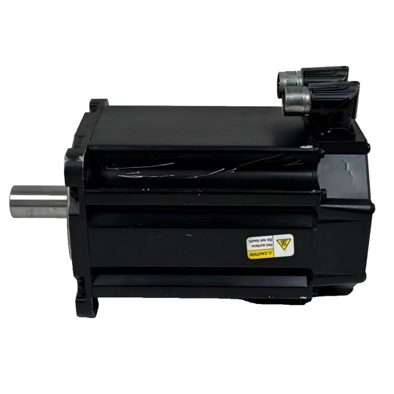
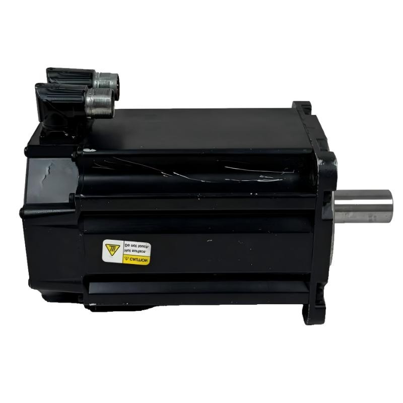
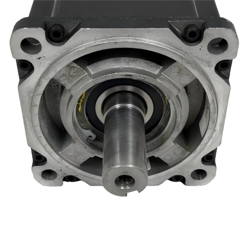
- Allen Bradley
- MPL-B680H-SJ74AA
- Low-Inertia Brushless Servo Motors Product
- USA
- 215 mm ×203.2 mm × 325 mm
- 42.7 kg
- Xiamen, China
- New & In Stock
- T/T, PayPal, Western Union
- 1 Year
- 1-3 Working Days
- DHL, UPS, TNT, FedEx and EMS.
- 24-Hour Service
- COO
- 3
Our advantage

Global Logistics
We have a 10-year logistics and express cooperation agreement, so our products can be shipped to any place in the world.

Brand new and original
Our products are imported in bulk from the place of origin. Because of the cooperative relationship, our products are all original and 100% new.

24-hour service
We provide 7*24 hours service to our customers. We will be there whenever you need us.

Price advantage
All our products are priced very favorably because we have our own warehouse and supply.
| Company Information | |||
| [email protected] | |||
| Mobile | +8615980777398 | ||
| +8615980777398 | |||
| 15980777398 |
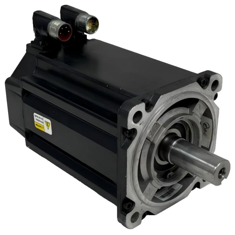
Allen-Bradley MPL-B680H-SJ74AA Servo Motor: Detailed Product Description, Technical Specifications, Applications, Advantages, and Related Models
1. Product Overview
The Allen-Bradley MPL-B680H-SJ74AA is a brushless AC servo motor in the MP-Series MPL low-inertia servo motor family. It is designed for industrial automation systems that require accurate rotary motion, controlled acceleration and deceleration, and repeatable positioning.
This motor is intended to operate as part of a closed-loop motion-control system. A compatible servo drive supplies and regulates motor power, while the feedback device provides position information to the control system. Together, these components allow machinery to follow programmed movement profiles, maintain controlled speed, and coordinate motion with other axes.
The MPL-B680H-SJ74AA belongs to a relatively large motor frame class and uses a high-speed motor configuration. Its keyed shaft supports mechanical connections to compatible couplings, pulleys, gears, and other transmission components. The model also includes a holding-brake option, which can be useful when the machine needs to resist shaft movement after the drive removes operating torque.
When selecting this motor for a new machine or as a replacement part, the complete catalog number matters. Models with similar names may have different speed ratings, encoder configurations, brake arrangements, connector types, and electrical requirements. Those differences can affect both mechanical installation and drive compatibility.
The following description provides the main product characteristics and practical selection guidance. Where complete dimensional or weight data cannot be confidently assigned to this exact catalog number, the relevant item is marked for confirmation rather than presented as a guaranteed specification.
2. Detailed Technical Parameters
2.1 Basic product and electrical parameters
|
Parameter |
Specification |
|---|---|
|
Model |
MPL-B680H-SJ74AA |
|
Brand |
Allen-Bradley |
|
Product family |
MP-Series |
|
Product series |
MPL low-inertia servo motors |
|
Product type |
Brushless AC rotary servo motor |
|
Motor construction |
Permanent-magnet rotor |
|
Phase configuration |
Three-phase |
|
Pole configuration |
Eight-pole motor family |
|
Voltage class |
460 V AC class |
|
Speed class |
3,500 RPM |
|
Maximum operating speed |
Up to 3,500 RPM, subject to the applicable motor specification |
|
Feedback type |
Single-turn high-resolution encoder |
|
Shaft configuration |
Keyed shaft extension |
|
Brake configuration |
Integrated holding brake |
|
Brake voltage |
24 V DC class; verify the exact electrical specification before wiring |
|
Connector arrangement |
SpeedTEC DIN connector, right-angle style, rotatable design |
|
Mounting style |
IEC metric mounting arrangement |
|
Frame size |
Size 6 |
|
Frame dimension |
Approximately 215 mm (8.46 in.) |
|
Magnet stack length |
Approximately 203.2 mm (8.00 in.) |
|
Cooling construction |
Totally enclosed, non-ventilated motor design |
|
Control method |
Closed-loop servo control |
|
Intended environment |
Industrial automation installations within the specified operating limits |
The voltage class and speed rating should be checked against the motor nameplate and the applicable technical specification before the motor is connected to a drive. A 460 V-class motor must not be treated as interchangeable with a lower-voltage model simply because the mechanical frame appears similar.
2.2 Torque, current, and output characteristics
The values below are reference figures for the relevant motor family and should be confirmed against the exact MPL-B680H-SJ74AA specification before being used for engineering calculations.
|
Parameter |
Reference value |
Notes |
|---|---|---|
|
Continuous stall torque |
Up to approximately 60 Nm |
Operating conditions and cooling affect usable torque |
|
Continuous stall torque with specified forced cooling |
Up to approximately 81.3 Nm |
Applicable only where the relevant cooling arrangement is supported |
|
Peak stall torque |
Up to approximately 146.9 Nm |
Peak torque is subject to drive and duty-cycle limits |
|
Continuous stall current |
Up to approximately 51 A |
Verify drive sizing and motor electrical data |
|
Peak stall current |
Up to approximately 140 A |
Short-duration peak value; not a continuous operating current |
|
Maximum continuous output rating |
Approximately 7.5 kW at 2,000 RPM |
Reference family rating; confirm exact model data |
|
Maximum speed class |
3,500 RPM |
Actual operating limits depend on the motor and drive combination |
Torque and current figures should not be considered independent of speed, temperature, cooling, and duty cycle. For example, a motor may be able to deliver high torque briefly while requiring a lower torque level for continuous operation. The correct motor sizing process must consider the load profile, acceleration demand, stopping frequency, and thermal conditions.
2.3 Dimensions and weight
|
Parameter |
Specification |
|---|---|
|
Frame dimension |
Approximately 215 mm |
|
Magnet stack length |
Approximately 203.2 mm |
|
Overall motor length |
Confirm using the exact dimensional drawing |
|
Overall motor width |
Confirm using the exact dimensional drawing |
|
Overall motor height |
Confirm using the exact dimensional drawing |
|
Shaft diameter |
Confirm using the exact dimensional drawing |
|
Shaft extension length |
Confirm using the exact dimensional drawing |
|
Keyway dimensions |
Confirm using the exact dimensional drawing |
|
Mounting-hole spacing |
Confirm using the exact dimensional drawing |
|
Flange dimensions |
Confirm using the exact dimensional drawing |
|
Product weight (kg) |
Approximately 40.45 kg as a family reference value; confirm the exact model |
|
Shipping weight (kg) |
Approximately 42.7 kg as a family reference value; packaging may vary |
|
Installation clearance |
Allow sufficient space for the motor body, connector, cables, and service access |
The frame dimension and stack length describe key parts of the motor’s size classification, but they are not a substitute for the full mechanical drawing. Overall length can vary with shaft, connector, and brake configuration. For a replacement installation, confirm the flange, mounting-hole pattern, shaft dimensions, connector clearance, and brake wiring requirements before ordering.
3. Product Introduction
The MPL-B680H-SJ74AA is built for machine systems where a motor must do more than rotate continuously. In a servo application, the motor needs to respond to commands from the motion controller, accelerate or decelerate according to a defined profile, and reach the required position with consistent timing.
Its low-inertia design is useful in applications that involve frequent speed changes, repeated indexing, and coordinated movement. The motor can be paired with a compatible servo drive and controller to form a motion axis for machinery such as packaging equipment, automated assembly systems, and production machines.
The single-turn high-resolution encoder supplies position feedback within one revolution. This allows the control system to monitor shaft position and correct motion as needed. Because it is a single-turn feedback configuration, users should verify that its position-tracking behavior matches the application, particularly when the machine must retain or track position across multiple revolutions or after power loss.
The keyed shaft provides a positive mechanical interface for compatible couplings and transmission components. The right-angle connector is rotatable, which can make cable routing easier in compact machinery. The integrated 24 V DC holding brake is intended to help hold the shaft when the motor is stopped and the brake is engaged.
The brake should not be treated as a substitute for a properly engineered safety system. For vertical axes, suspended loads, or mechanisms where unexpected movement could cause injury or damage, the complete design should account for braking capacity, load retention, control behavior, and applicable safety requirements.
4. Product Applications

4.1 Packaging and filling machinery
Packaging lines often require coordinated conveyor movement, product spacing, cutting, sealing, and indexing. A servo motor can follow programmed motion profiles to help synchronize these operations. The MPL-B680H-SJ74AA may be considered where the required speed, torque, and brake configuration match the machine design.

4.2 Automated assembly equipment
Assembly machines frequently move components between defined positions. Servo control can support repeatable indexing, controlled approach speeds, and coordinated sequences. The motor’s encoder feedback can help the controller monitor motion during repeated production cycles.

4.3 Machine tools and precision manufacturing
Automated manufacturing equipment may use servo axes for rotary positioning, tool handling, material feeding, or auxiliary motion. The suitability of this motor depends on the required torque curve, mechanical stiffness, positioning tolerance, and the compatibility of the drive and feedback interface.

4.4 Material handling and transfer systems
Transfer mechanisms, indexing tables, and automated handling systems often need controlled acceleration and repeatable stopping positions. A servo motor can support these movements when properly sized for the load and transmission. The integrated brake may be relevant where the machine design requires a holding function.

4.5 Rotary indexing and positioning equipment
Rotary tables and indexing mechanisms need to move between specified angles and settle before the next operation. A closed-loop servo system can control these movements according to the machine’s motion program. The required resolution, settling time, torque, and stopping behavior should be evaluated as part of the system design.
Additional potential applications
The motor may also be evaluated for the following types of equipment, provided the operating requirements fall within its specifications:
-
Automated inspection and testing machinery.
-
Printing, labeling, and converting equipment.
-
Industrial feeders and synchronized transfer mechanisms.
-
Pick-and-place machinery and component positioning systems.
-
General-purpose multi-axis automation equipment.
These are potential application categories, not a guarantee that the motor is suitable for every machine in each category. The final choice should be based on load calculations, duty cycle, motion profile, environment, and drive compatibility.
5. Product Advantages
5.1 High-speed motion capability
The 3,500 RPM speed class makes this motor a candidate for applications that require relatively fast rotary motion. High-speed capability can be useful when a production cycle contains frequent movement or when a machine needs to complete a rotary operation within a limited time.
However, speed alone does not determine machine performance. The available torque at the intended speed, the load inertia, and the mechanical transmission must all be considered. A motor that can reach a high speed is not necessarily the best choice if the application requires sustained high torque at that speed.
5.2 High-resolution feedback for closed-loop control
The single-turn high-resolution encoder provides position feedback to the servo control system. This enables the drive and controller to monitor the motor’s movement and respond to position error.
When the complete motion system is properly configured, feedback can help improve repeatability, reduce positioning error, and support consistent cycle-to-cycle operation. The achievable result depends on the entire machine, including the drive, controller, mechanical assembly, tuning, and external load.
5.3 Low-inertia construction
Low-inertia servo motors are often selected for machines that need frequent acceleration, deceleration, or direction changes. A motor with suitable rotor inertia can respond effectively to changing motion commands, particularly when matched to the load inertia.
This can be valuable in indexing, automated handling, and other applications that repeat short movements throughout a production cycle. The actual dynamic response still depends on the drive’s capability, control settings, load characteristics, and mechanical stiffness.
5.4 Integrated 24 V DC holding brake
The integrated brake is a useful feature when a machine requires a holding function after the motor stops. It can help resist unwanted shaft movement when correctly wired and operated according to the motor’s specifications.
Brake selection requires attention to the type of load and the intended function. A holding brake is generally designed to hold a stationary load, not to perform frequent dynamic emergency stops unless specifically rated for that purpose. For safety-related applications, the brake must be considered as part of the complete engineered system.
5.5 Keyed shaft for mechanical integration
The keyed shaft provides a conventional interface for compatible mechanical components. It can be used with appropriately designed couplings, pulleys, gears, and other drive elements.
The shaft key and mating component must be selected to suit the transmitted torque and mechanical conditions. Shaft diameter, keyway size, shaft extension length, alignment, and coupling limits should be checked before installation.
5.6 Rotatable right-angle connector
The SpeedTEC DIN right-angle connector can make cable routing more convenient where space around the motor is restricted. Its rotatable arrangement may help the installer orient the connector to reduce interference with nearby machine components.
The final cable route should preserve the required bend radius and avoid excessive tension, abrasion, heat exposure, or contact with moving parts. Connector orientation should also allow access for maintenance and inspection.
5.7 Designed for industrial automation
The MPL series is intended for industrial motion-control applications. When correctly matched with a compatible drive and controller, the motor can be integrated into a broader automation system with coordinated movement and repeatable operating sequences.
This can help machine designers build controlled motion into production equipment without relying solely on open-loop motor operation.
5.8 Brake and feedback options are identifiable in the catalog number
The full model number distinguishes important configuration details. For this model, the configuration includes single-turn high-resolution feedback, a keyed shaft, a right-angle rotatable connector, and a 24 V DC holding brake.
That makes the complete catalog number especially important during replacement. A motor with a similar frame and speed may still have a different encoder or brake arrangement, which can affect wiring, drive setup, mechanical fit, and machine behavior.
6. Brand and Product Series
|
Parameter |
Description |
|---|---|
|
Brand |
Allen-Bradley |
|
Product family |
MP-Series |
|
Product series |
MPL |
|
Series description |
Low-inertia brushless servo motors |
|
Product category |
Rotary AC servo motor |
|
Motor technology |
Brushless permanent-magnet construction |
|
Voltage class |
460 V AC |
|
Speed class |
3,500 RPM |
|
Frame dimension |
215 mm |
|
Magnet stack length |
203.2 mm |
|
Feedback |
Single-turn high-resolution encoder |
|
Shaft |
Keyed shaft extension |
|
Connector |
Right-angle, rotatable SpeedTEC DIN |
|
Brake |
24 V DC holding brake |
|
Mounting |
IEC metric, free mounting holes |
|
Primary purpose |
Controlled rotary motion and positioning |
The MP-Series MPL family is intended for servo applications in which dynamic response and controlled movement are important. Within the family, different model variants offer different frame sizes, magnet stack lengths, speed classes, feedback types, shaft configurations, and brake options.
When choosing a model within the same series, users should compare the complete catalog number rather than relying on a single feature such as frame size or rated speed. Mechanical similarity does not necessarily mean electrical or feedback compatibility.
7. Five Recommended Models from the Same Series or Closely Related Variants
The following models are useful comparison candidates when selecting a motor with a similar frame size or a related MPL configuration. The key differences are speed class, feedback type, and brake option. The listed dimensions are nominal frame and stack dimensions; complete external dimensions and exact net weights should be verified for the individual catalog number.
|
Model |
Series |
Voltage class |
Speed class |
Frame dimension |
Stack length |
Feedback |
Brake |
Dimensions and weight |
|---|---|---|---|---|---|---|---|---|
|
MPL-B680H-SJ74AA |
MPL |
460 V AC |
3,500 RPM |
215 mm |
203.2 mm |
Single-turn high-resolution |
24 V DC |
Frame 215 mm; stack 203.2 mm; exact external dimensions and net weight to be confirmed |
|
MPL-B680H-MJ74AA |
MPL |
460 V AC |
3,500 RPM |
215 mm |
203.2 mm |
Multi-turn high-resolution |
24 V DC |
Frame 215 mm; stack 203.2 mm; exact external dimensions and net weight to be confirmed |
|
MPL-B680H-SJ72AA |
MPL |
460 V AC |
3,500 RPM |
215 mm |
203.2 mm |
Single-turn high-resolution |
No integrated brake |
Frame 215 mm; stack 203.2 mm; exact external dimensions and net weight to be confirmed |
|
MPL-B680H-MJ72AA |
MPL |
460 V AC |
3,500 RPM |
215 mm |
203.2 mm |
Multi-turn high-resolution |
No integrated brake |
Frame 215 mm; stack 203.2 mm; exact external dimensions and net weight to be confirmed |
|
MPL-B680F-SJ74AA |
MPL |
460 V AC |
3,000 RPM |
215 mm |
203.2 mm |
Single-turn high-resolution |
24 V DC |
Frame 215 mm; stack 203.2 mm; exact external dimensions and net weight to be confirmed |
7.1 How these related models differ
MPL-B680H-MJ74AA — multi-turn feedback with brake
This is a comparison candidate when the application requires a multi-turn encoder configuration as well as a holding brake. Multi-turn feedback can be relevant when the control system needs to track position across multiple shaft revolutions. Confirm the encoder’s behavior, backup requirements, and drive compatibility before substitution.
MPL-B680H-SJ72AA — single-turn feedback without brake
This version is worth considering when the application uses the same general motor size and speed class but does not require an integrated brake. It may suit axes that do not need the motor to hold a load mechanically after power is removed. It should not replace a braked model where the machine relies on the brake to retain a load.
MPL-B680H-MJ72AA — multi-turn feedback without brake
This model combines the higher speed class with multi-turn feedback and no integrated holding brake. It may be appropriate for applications where multi-turn position tracking is required and a motor-mounted brake is unnecessary or handled by a separate engineered mechanism.
MPL-B680F-SJ74AA — lower speed class with brake
The F speed code identifies a 3,000 RPM class rather than the 3,500 RPM class of the H variant. It is a candidate when the required operating speed is lower and the brake and single-turn feedback configuration remain suitable. The torque-speed curve and the machine’s cycle time should be checked before making a selection.
MPL-B680H-SJ74AA — the reference model
The target model combines the 3,500 RPM speed class, single-turn high-resolution feedback, keyed shaft, rotatable right-angle connector, and 24 V DC holding brake. It is a reasonable starting point for comparisons where those features are required, but the final selection must still match the load and drive specifications.
8. Five Additional Allen-Bradley Servo Motor Models to Consider
These additional models broaden the comparison to other frame sizes, speed classes, and voltage classes within the same general servo motor product family. They should be treated as candidates for evaluation, not as direct replacements for the MPL-B680H-SJ74AA.
|
Model |
Product series |
Voltage class |
Speed class |
Frame dimension |
Stack length |
Configuration |
Dimensions and weight (kg) |
|---|---|---|---|---|---|---|---|
|
MPL-B560F-MJ72AA |
MPL |
460 V AC |
3,000 RPM |
165 mm |
152.4 mm |
Multi-turn feedback; no brake |
Frame 165 mm; stack 152.4 mm; exact external dimensions and net weight to be confirmed |
|
MPL-B4540F-SJ72AH |
MPL |
460 V AC class |
3,000 RPM class |
Verify exact model drawing |
Verify exact model drawing |
Single-turn feedback; no brake indicated by catalog code |
Confirm dimensions and net weight from the exact model documentation |
|
MPL-B330P-MJ72AH |
MPL |
460 V AC class |
5,000 RPM class |
Verify exact model drawing |
Verify exact model drawing |
Multi-turn feedback; no brake indicated by catalog code |
Confirm dimensions and net weight from the exact model documentation |
|
MPL-A220T-EJ72AA |
MPL |
230 V AC class |
6,000 RPM class |
Verify exact model drawing |
Verify exact model drawing |
Lower-voltage-class variant; confirm exact feedback and brake configuration |
Confirm dimensions and net weight from the exact model documentation |
|
MPL-B540K-SJ74AA |
MPL |
460 V AC class |
4,000 RPM class |
165 mm class |
101.6 mm class |
Single-turn feedback; 24 V DC brake |
Confirm exact external dimensions and net weight from the exact model documentation |
Important model-selection note: Catalog codes can be easy to misread, especially when several characters distinguish frame size, stack length, speed, feedback, and brake configuration. Before purchasing any comparison model, confirm its complete catalog number, electrical ratings, mounting dimensions, connector, encoder interface, and brake option. Where the dimensions or weight are not confidently established, they are intentionally marked for verification rather than guessed.
9. Product Dimensions and Weight: Selection Checklist
For an industrial servo motor replacement, a single frame measurement is not enough to confirm a mechanical fit. The following table lists the measurements and ratings that should be checked before ordering.
|
Item to verify |
MPL-B680H-SJ74AA reference information |
Why it matters |
|---|---|---|
|
Frame dimension |
215 mm |
Determines the general motor mounting size |
|
Magnet stack length |
203.2 mm |
Helps identify the motor’s active stack configuration |
|
Overall length |
Verify exact drawing |
Prevents interference with guards, couplings, and adjacent machinery |
|
Overall width |
Verify exact drawing |
Important for enclosure and machine clearance |
|
Overall height |
Verify exact drawing |
Important for installation space and connector clearance |
|
Flange and mounting pattern |
IEC metric; confirm drawing |
Ensures the motor can be installed on the existing mounting surface |
|
Shaft diameter |
Verify exact drawing |
Must match the coupling, pulley, or gearbox input |
|
Shaft extension and keyway |
Keyed shaft; verify detailed dimensions |
Affects coupling engagement and torque transmission |
|
Connector orientation |
Right-angle, rotatable connector |
Affects cable routing and service access |
|
Product weight (kg) |
Exact net weight must be confirmed |
Relevant to lifting, support, and shipping planning |
|
Shipping weight (kg) |
Depends on packaging and shipment |
Relevant to freight and handling arrangements |
|
Brake |
24 V DC holding brake |
Must match the control and holding requirements |
|
Feedback |
Single-turn high-resolution encoder |
Must be compatible with the servo drive and controller |
Weight clarification
Weight values can differ between product listings because some refer to the motor alone, while others include packaging or use a different data field. For that reason, the exact net weight of the MPL-B680H-SJ74AA should be confirmed from the product label or the applicable technical drawing before using it for lifting calculations or mechanical support design.
For a replacement project, it is best to obtain the dimensional drawing for the exact catalog number and compare it directly with the motor being removed. Even if the replacement has the same frame dimension and stack length, differences in shaft, connector, brake, or flange details can still prevent a direct installation.
10. Installation and Compatibility Considerations
10.1 Servo drive compatibility
The motor must be paired with a drive that supports its voltage class, current requirements, feedback device, and brake arrangement. Check the drive’s supported motor list and feedback interface before connecting the motor. A mechanically compatible motor may still be electrically incompatible with the existing system.
10.2 Encoder and controller setup
The single-turn high-resolution encoder must be recognized correctly by the drive and motion controller. The control system should be configured for the correct motor identity and feedback type. Incorrect motor selection or feedback settings can result in motion errors, alarms, poor positioning, or unexpected machine behavior.
10.3 Brake wiring and operation
The integrated brake is a 24 V DC holding brake. Confirm the brake wiring, supply requirements, and operating sequence in the applicable documentation. The brake should be released and engaged according to the intended control sequence, and its suitability for the actual load must be evaluated separately from the motor’s torque rating.
10.4 Mechanical alignment
Correct alignment between the motor shaft and the driven mechanism helps avoid unnecessary radial or axial loading. Couplings, gears, and pulleys must be selected for the required torque and speed. Shaft key dimensions and allowable shaft loads should be checked against the detailed mechanical specification.
10.5 Thermal and duty-cycle requirements
The required torque, speed, acceleration, and duty cycle determine the motor’s thermal load. Continuous and peak ratings serve different purposes. A motor that meets a brief peak demand may not be suitable if that demand occurs frequently or lasts too long.
10.6 Maintenance access
The connector, motor body, and mounting fasteners should remain accessible for inspection and servicing. Cable routing should avoid sharp edges, moving components, excessive tension, and sources of high temperature. Installation should also provide suitable clearance for the motor’s operating environment.
11. How to Choose Between Similar Models
The most suitable model depends on the machine’s actual operating requirements rather than the model number alone.
|
Application requirement |
Selection consideration |
|---|---|
|
High operating speed |
Compare the required speed with the motor’s speed class and torque-speed curve |
|
Frequent acceleration and stopping |
Evaluate inertia matching, peak torque, drive capability, and duty cycle |
|
Position tracking across multiple turns |
Determine whether multi-turn feedback is required |
|
Holding a stationary load |
Confirm whether a motor-mounted brake is needed and adequately rated |
|
Compact mechanical installation |
Compare frame size, stack length, shaft dimensions, and connector clearance |
|
Replacement of an existing motor |
Match the complete catalog number and verify all electrical and mechanical interfaces |
|
Existing servo drive must be retained |
Confirm the motor is supported by the exact drive and firmware configuration |
|
Continuous high torque |
Calculate the load profile and verify continuous torque and thermal limits |
|
Vertical or gravity-loaded axis |
Review brake capacity and the complete machine’s load-retention and safety design |
For most replacement projects, the safest starting point is to match the original catalog number exactly. If the original model is unavailable, choose an alternative only after confirming that the electrical, feedback, brake, shaft, flange, and performance requirements are satisfied.
12. Summary of the MPL-B680H-SJ74AA
The Allen-Bradley MPL-B680H-SJ74AA is a 460 V-class, 3,500 RPM brushless AC servo motor in the MP-Series MPL low-inertia family. Its principal configuration includes a 215 mm frame dimension, 203.2 mm magnet stack length, single-turn high-resolution encoder, keyed shaft, rotatable right-angle connector, and 24 V DC holding brake.
Its main strengths are the combination of closed-loop motion capability, high-speed operation, low-inertia design, and an integrated holding brake. These characteristics make it a candidate for automated machinery requiring controlled rotary movement and repeatable positioning.
The most important checks before selection are the motor’s torque and current requirements, encoder compatibility, brake needs, mounting and shaft dimensions, and exact net weight. The nominal frame and stack measurements are useful for identifying the motor class, but the complete dimensional drawing is required to establish a reliable mechanical fit.
When comparing related models, the MPL-B680H-MJ74AA, MPL-B680H-SJ72AA, MPL-B680H-MJ72AA, and MPL-B680F-SJ74AA are useful candidates because they share much of the same general configuration while differing in feedback, brake option, or speed class. Any substitution should be approved only after the relevant specifications have been checked against the machine and drive requirements.