

ProductPRODUCT
Featured products

Contact Us
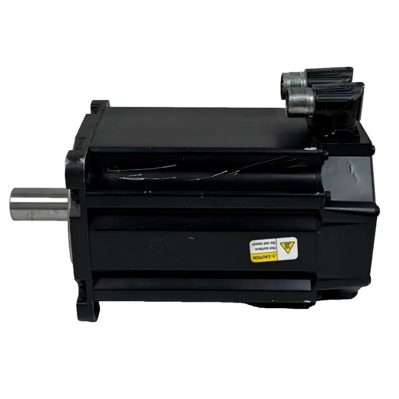
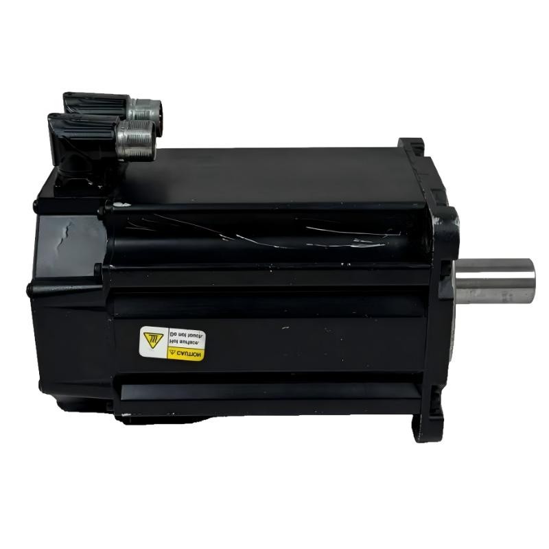
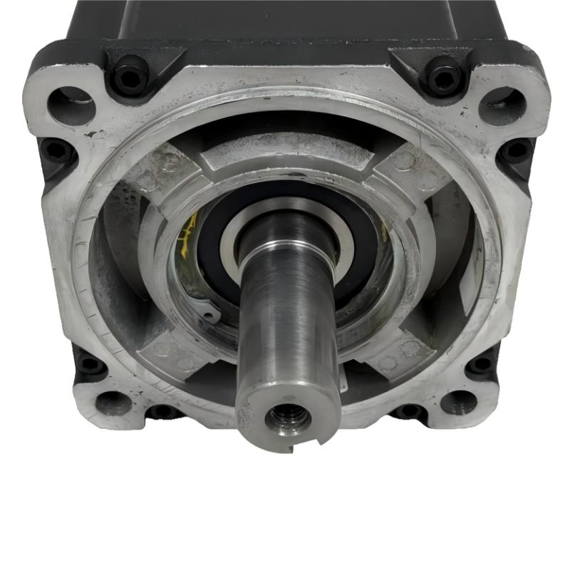
- Allen Bradley
- MPL-B880D-MJ74AA
- Low-Inertia Brushless Servo Motors Product
- USA
- 215 mm ×203.2 mm × 325 mm
- 42.7 kg
- Xiamen, China
- New & In Stock
- T/T, PayPal, Western Union
- 1 Year
- 1-3 Working Days
- DHL, UPS, TNT, FedEx and EMS.
- 24-Hour Service
- COO
- 6
Our advantage

Global Logistics
We have a 10-year logistics and express cooperation agreement, so our products can be shipped to any place in the world.

Brand new and original
Our products are imported in bulk from the place of origin. Because of the cooperative relationship, our products are all original and 100% new.

24-hour service
We provide 7*24 hours service to our customers. We will be there whenever you need us.

Price advantage
All our products are priced very favorably because we have our own warehouse and supply.
| Company Information | |||
| [email protected] | |||
| Mobile | +8615980777398 | ||
| +8615980777398 | |||
| 15980777398 |
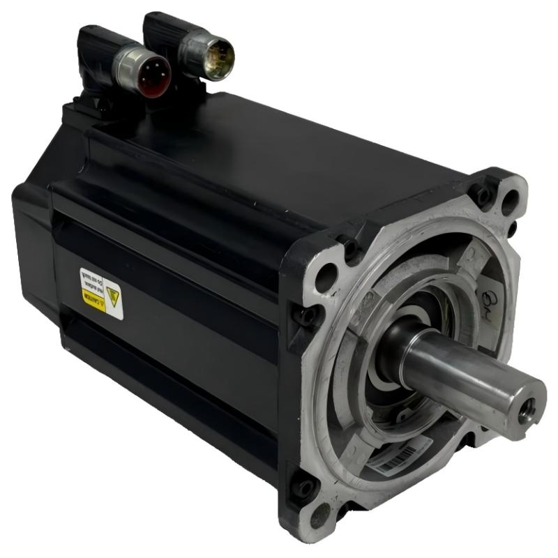
Allen-Bradley MPL-B880D-MJ74AA Servo Motor: Detailed Product Description, Specifications, Applications, Advantages, and Related Models
1. Product Overview
The Allen-Bradley MPL-B880D-MJ74AA is a low-inertia brushless AC rotary servo motor designed for industrial motion-control systems that require accurate positioning, controlled acceleration, and repeatable movement. It belongs to the MP-Series MPL family and is designed to work with a compatible servo drive and motion controller.
This model combines a 460 V AC motor configuration, a nominal speed rating of 2,000 RPM, a multi-turn high-resolution absolute feedback encoder, a keyed shaft, and an integrated 24 V DC holding brake. The brake is particularly useful in applications where a vertical axis or mechanically loaded shaft needs to be held when the motor is stopped or the drive is disabled.
The motor is intended for machinery that needs controlled rotary motion rather than simple continuous rotation. Depending on the drive, mechanical transmission, and control program, it can support coordinated movement, repeatable indexing, acceleration and deceleration profiles, and accurate stopping at programmed positions.
Its frame and magnet-stack designations identify a relatively large motor configuration within the MPL family. The frame size is designated as 265 mm, and the magnet stack length is 203.2 mm. These are useful selection references, but they are not the complete external dimensions of the assembled motor.
2. Brand and Product Series
|
Item |
Description |
|---|---|
|
Model |
|
|
Brand |
Allen-Bradley |
|
Product family |
MP-Series |
|
Product series |
MPL low-inertia brushless servo motors |
|
Product type |
AC rotary servo motor |
|
Motor design |
Brushless servo motor |
|
Voltage class |
460 V AC |
|
Nominal speed |
2,000 RPM |
|
Feedback |
Multi-turn, high-resolution absolute encoder |
|
Shaft |
Keyed shaft extension |
|
Holding brake |
Integrated 24 V DC brake |
|
Connector |
Right-angle SpeedTEC DIN quick-connect connector, rotatable through 180° |
|
Frame designation |
Size 8, nominal frame dimension 265 mm |
|
Magnet stack length |
203.2 mm |
|
Mounting arrangement |
IEC metric, free mounting holes, Type FF |
|
Overall dimensions |
Confirm using the exact mechanical outline drawing |
|
Weight |
Approximately 86.7 kg; confirm against the specific motor version and documentation |
The MPL designation identifies the low-inertia motor family. Low-inertia construction is intended to support responsive motion control, while the encoder and compatible servo drive provide the feedback and control functions needed for closed-loop operation.
The MJ74AA configuration is important when selecting a replacement. It identifies a particular combination of feedback, shaft, connector, brake, and mechanical configuration. A motor with a similar base number may have a different brake or encoder arrangement, so the full catalog number should be checked before ordering.
3. Detailed Technical Specifications
The following table summarizes the main selection and installation characteristics of the MPL-B880D-MJ74AA. Values that depend on the complete motor assembly, feedback configuration, or installation arrangement should be verified against the exact unit.
|
Parameter |
Specification |
|---|---|
|
Model |
MPL-B880D-MJ74AA |
|
Motor type |
Brushless AC rotary servo motor |
|
Rated voltage class |
460 V AC |
|
Nominal speed |
2,000 RPM |
|
Rated output power |
Approximately 12.6 kW |
|
Continuous stall torque |
Approximately 110 N·m |
|
Peak stall torque |
Approximately 147 N·m |
|
Feedback device |
Multi-turn, high-resolution absolute encoder |
|
Feedback function |
Provides rotor-position feedback for closed-loop control |
|
Shaft design |
Keyed shaft extension |
|
Brake type |
Integrated 24 V DC holding brake |
|
Brake purpose |
Helps hold the shaft or load when the motor is stopped, subject to correct system design |
|
Power and feedback connections |
Right-angle SpeedTEC DIN quick-connect connector |
|
Connector adjustment |
Rotatable through 180° |
|
Frame size designation |
Size 8, nominally 265 mm |
|
Magnet stack length |
203.2 mm |
|
Mounting style |
IEC metric, Type FF free mounting holes |
|
Overall dimensions |
Use the exact mechanical outline drawing for length, width, height, shaft extension, and mounting-hole positions |
|
Approximate motor weight |
86.7 kg |
|
Cooling and installation |
Follow the motor-specific installation requirements and the selected drive’s instructions |
|
Control method |
Closed-loop servo control with a compatible servo drive |
|
Typical operating role |
Precision rotary motion, positioning, indexing, and controlled acceleration or deceleration |
Important specification note: The 2,000 RPM figure is the motor’s nominal speed rating, not a guarantee that the motor can deliver the same torque at every speed. Actual operating torque, speed, current, and power depend on the selected drive, supply conditions, load, duty cycle, and thermal limits.
The approximate weight is intended for preliminary equipment planning. For lifting, mounting, shipping, or structural calculations, use the confirmed weight and mechanical drawing for the exact unit.
4. Product Introduction
The MPL-B880D-MJ74AA is designed for machinery where the motor must respond predictably to commands from a motion controller. Rather than running continuously at a fixed speed, it can be used as part of a servo axis that changes speed, stops at programmed positions, or follows a coordinated motion profile.
A typical servo system consists of the motor, a compatible servo drive, a controller, feedback connections, and the mechanical equipment being moved. The controller generates the motion command, the drive supplies controlled electrical power to the motor, and the encoder provides position information for the control loop.
This arrangement allows the machine to correct motion errors during operation. If the axis is required to reach a particular position, the control system can compare the commanded position with the feedback position and adjust the motor response accordingly.
The motor’s low-inertia design is useful in applications where acceleration and deceleration are frequent. The 2,000 RPM nominal speed and substantial torque capability make it a candidate for demanding industrial axes, although suitability must be assessed against the actual load inertia, required cycle time, transmission ratio, and duty cycle.
Another defining feature is the integrated 24 V DC brake. This is valuable when a machine axis needs additional holding capability while stationary. The brake is not a substitute for a properly designed safety system, and it should not be assumed to provide dynamic stopping unless the motor and application documentation explicitly permits that use.
5. Main Product Features
5.1 Low-inertia motor design
The low-inertia construction is intended to support responsive changes in speed and direction. This can be useful in equipment that repeatedly accelerates, decelerates, indexes, or changes position within a short production cycle.
In a properly sized system, responsive motor dynamics can help improve cycle consistency and reduce unnecessary delays between machine movements. The actual result depends on the total inertia of the motor, gearbox, coupling, and driven load.
5.2 Multi-turn absolute feedback
The multi-turn absolute encoder provides position feedback that includes rotational information beyond a single revolution. This can be useful when a machine axis needs to retain meaningful position information over a wider range of movement.
The encoder must be compatible with the selected drive and controller. The motor’s absolute-feedback capability does not automatically guarantee that every machine will restart at its previous position without a homing or recovery procedure; this depends on the drive configuration, feedback handling, and machine control design.
5.3 Integrated 24 V DC holding brake
The brake is a significant distinction between the MJ74AA and otherwise similar no-brake versions. It can help hold a stationary shaft or load, especially when gravity or an external force could cause unwanted movement.
Brake selection should take into account the load, transmission ratio, holding torque requirement, stopping strategy, and brake operating limits. On a vertical axis, a separate mechanical safety measure may also be required by the machine design.
5.4 Keyed shaft extension
The keyed shaft provides a mechanical interface for compatible couplings, pulleys, or other drive components. The key helps transmit torque between the shaft and the attached component when the connection is correctly designed and installed.
The mating component must match the shaft dimensions, keyway, allowable loads, and alignment requirements. Incorrect coupling or alignment can create vibration, excessive bearing loads, and premature wear.
5.5 Right-angle quick-connect connector
The right-angle SpeedTEC DIN connector is designed to provide a compact cable connection. Its 180° rotation capability offers flexibility when the motor is installed in machinery with restricted cable routing or limited access.
The connector orientation should be planned before installation to avoid excessive cable bending, interference with guards, and unnecessary strain on the cable assembly.
5.6 Industrial mounting arrangement
The IEC metric mounting configuration helps the motor integrate into appropriately designed industrial machinery. The frame and stack designations provide useful starting points for mechanical comparison, but mounting-hole spacing, shaft projection, flange details, and the total motor envelope must still be checked against the mechanical drawing.
6. Typical Applications

6.1 Packaging and converting equipment
The motor can be considered for indexing mechanisms, feed rollers, cutting axes, sealing mechanisms, and other packaging-machine movements where controlled speed and repeatable positioning are required. The final selection depends on the inertia of the moving parts, the required cycle rate, and the peak torque during acceleration.

6.2 Automated assembly systems
Assembly machinery often combines repeated positioning with coordinated movements between stations. A servo motor can operate a rotary indexer, transfer mechanism, or other controlled axis, provided that the drive and mechanics are correctly sized for the load.

6.3 Material handling and transfer equipment
The motor may be suitable for powered transfer mechanisms, rotary handling units, and selected positioning axes. Where a vertical or gravity-loaded axis is involved, the integrated holding brake may be useful, but the complete load-holding and safety design must be evaluated separately.

6.4 Machine tools and specialized machinery
Servo motors are commonly used for controlled feed axes, rotary mechanisms, and automated tool-handling functions. For this model, confirm the required speed-torque curve, duty cycle, mechanical stiffness, and compatibility with the machine’s motion-control architecture before selecting it.

6.5 Rotary tables and indexing mechanisms
A servo-controlled rotary table may need to accelerate, reach a programmed angle, settle, and repeat the movement over many production cycles. The encoder feedback and controlled drive system can support this type of operation when the motor, reducer, table inertia, and controller are appropriately matched.
These are representative application categories rather than a guarantee of suitability for every machine. Final selection should be based on the actual motion profile, required accuracy, load, environmental conditions, and drive compatibility.
7. Main Advantages
Responsive motion control. The low-inertia design is intended to support dynamic motion profiles, making the motor a candidate for machinery with frequent acceleration, deceleration, and indexing.
High torque capability. The approximately 110 N·m continuous stall torque and approximately 147 N·m peak stall torque provide useful initial reference values for evaluating demanding axes. They should not be interpreted as torque available continuously at all speeds.
Multi-turn absolute feedback. The encoder configuration supports applications that need position information over multiple revolutions, subject to correct drive and controller integration.
Integrated holding brake. The 24 V DC brake can help hold a stationary load and is an important feature when evaluating vertical axes or other mechanisms where unintended movement must be controlled.
Flexible cable orientation. The rotatable right-angle connector can simplify cable routing and improve installation flexibility in compact machinery.
Established servo-motor format. The MP-Series MPL design gives equipment designers a defined motor family to compare against other compatible configurations, particularly when maintaining or upgrading existing machinery.
Mechanical connection flexibility. The keyed shaft provides a familiar interface for suitable couplings and transmission components, subject to the shaft and keyway specifications.
8. Model Number Explanation
The catalog number identifies the motor’s configuration. The following is a practical reading of the main code sections; the full manufacturer catalog coding information should be used for formal engineering interpretation.
|
Code section |
General meaning |
|---|---|
|
MPL |
MPL low-inertia brushless servo motor family |
|
B |
Voltage and product configuration code |
|
880 |
Motor frame and magnet-stack size designation |
|
D |
2,000 RPM nominal speed configuration |
|
M |
Multi-turn high-resolution absolute feedback |
|
J |
Keyed shaft extension |
|
7 |
Right-angle SpeedTEC DIN connector, rotatable through 180° |
|
4 |
24 V DC brake configuration |
|
AA |
Additional catalog configuration designation |
The most important practical point is to preserve the entire catalog number when comparing motors. A model that differs only in the brake or feedback code may require different wiring, drive settings, or machine-control procedures.
9. Five Related Models in the MPL Family
The models below are useful comparison candidates because they share the MPL family and have similar application roles. They are not automatic drop-in replacements. Check the complete catalog number, electrical ratings, mechanical drawing, encoder compatibility, and brake requirements before substituting one model for another.
|
Model |
Nominal voltage |
Speed |
Continuous / peak stall torque |
Feedback |
Brake |
Frame / stack length |
Approx. weight |
|---|---|---|---|---|---|---|---|
|
MPL-B880D-MJ72AA |
460 V AC |
2,000 RPM |
110 / 147 N·m |
Multi-turn absolute |
No brake |
265 / 203.2 mm |
86.7 kg |
|
MPL-B880D-SJ74AA |
460 V AC |
2,000 RPM |
110 / 147 N·m |
Single-turn absolute |
24 V DC |
265 / 203.2 mm |
Approx. 86.7 kg |
|
MPL-B880D-SJ72AA |
460 V AC |
2,000 RPM |
110 / 147 N·m |
Single-turn absolute |
No brake |
265 / 203.2 mm |
Approx. 86.7 kg |
|
MPL-B880C-MJ72AA |
460 V AC |
1,500 RPM |
110 / 203 N·m |
Multi-turn absolute |
No brake |
265 / 203.2 mm |
72.7 kg |
|
MPL-B860D-MJ72AA |
460 V AC |
2,000 RPM |
83 / 152.5 N·m |
Multi-turn absolute |
No brake |
265 / 152.4 mm |
67.5 kg |
Frame and stack values are nominal designations in millimetres. The weights marked approximate should be confirmed for the exact catalog variant. Overall external dimensions are not represented by frame size and stack length alone.
How to choose among these related models
– MPL-B880D-MJ72AA: Consider this configuration if the application needs the same general speed and torque class but does not require the integrated holding brake. Confirm whether the machine has a separate load-holding arrangement.
– MPL-B880D-SJ74AA: Consider it when a single-turn absolute feedback configuration is suitable and a 24 V DC brake is required. Verify the feedback requirements of the existing drive and controller.
– MPL-B880D-SJ72AA: This is a comparison option for applications that can use single-turn feedback and do not require the motor’s integrated brake.
– MPL-B880C-MJ72AA: This model has a lower nominal speed configuration and different peak-torque characteristics. It may be worth evaluating where the required speed and torque profile differs from the 2,000 RPM model.
– MPL-B860D-MJ72AA: This is a shorter-stack option within the family, with a different torque capability. It may suit a smaller load or a design with less available motor space, provided the calculated performance is sufficient.
10. Five Other Popular Allen-Bradley Servo Motor Models to Compare
The following models provide a broader comparison within the MPL motor range. They cover different speed and torque combinations, so they should be treated as selection candidates rather than interchangeable replacements.
|
Model |
Voltage class |
Nominal speed |
Continuous / peak stall torque |
Rated output power |
Frame / stack length |
Approx. weight |
|---|---|---|---|---|---|---|
|
MPL-B860D-MJ72AA |
460 V AC |
2,000 RPM |
83 / 152.5 N·m |
Approx. 12.5 kW |
265 / 152.4 mm |
67.5 kg |
|
MPL-B960B-MJ72AA |
460 V AC |
1,200 RPM |
130 / 231 N·m |
Approx. 12.7 kW |
Confirm drawing; 152.4 mm stack designation |
62.0 kg |
|
MPL-B960C-MJ72AA |
460 V AC |
1,500 RPM |
124.3 / 226 N·m |
Approx. 14.8 kW |
Confirm drawing; 152.4 mm stack designation |
76.0 kg |
|
MPL-B960D-MJ72AA |
460 V AC |
2,000 RPM |
124.3 / 226 N·m |
Approx. 15.0 kW |
Confirm drawing; 152.4 mm stack designation |
76.7 kg |
|
MPL-B980C-MJ72AA |
460 V AC |
1,500 RPM |
158.2 / 271 N·m |
Approx. 16.8 kW |
Confirm drawing; 203.2 mm stack designation |
67.3 kg |
The dimensions shown are nominal stack-length references, not complete motor dimensions. For the B960 and B980 variants, confirm the exact frame, flange, shaft, and overall dimensions from the applicable mechanical drawing. The approximate weights are for preliminary comparison only.
Comparison notes
MPL-B860D-MJ72AA offers a shorter magnet-stack designation and a lower continuous stall torque rating than the B880D model. It may be worth considering where the application has a lower torque requirement or a more restrictive installation envelope.
MPL-B960B-MJ72AA is a lower-speed configuration with a higher continuous stall torque rating than the B860D. It is worth evaluating for axes where torque and speed requirements differ from those of the 2,000 RPM model.
MPL-B960C-MJ72AA provides a 1,500 RPM nominal speed configuration and a different rated power and torque combination. The choice depends on the complete speed-torque curve and the required motion profile, not just the nominal speed.
MPL-B960D-MJ72AA is a 2,000 RPM configuration with a higher continuous stall torque rating than the B860D. It can be included in a comparison when evaluating a higher torque requirement, but the drive and mechanical system must be sized accordingly.
MPL-B980C-MJ72AA has a higher continuous stall torque rating and a different power rating from the B880D. It may be relevant to more demanding motion requirements, provided the required speed, duty cycle, drive compatibility, and mechanical envelope are satisfied.
11. Installation and Integration Considerations
11.1 Servo drive compatibility
The motor must be paired with a drive that supports the motor’s electrical ratings and feedback device. Confirm the required voltage class, continuous and peak current, feedback interface, motor identification, and supported configuration before commissioning.
A motor may fit mechanically while remaining incompatible with the existing drive. Electrical and feedback compatibility should therefore be checked before making a replacement decision.
11.2 Mechanical mounting and alignment
Use the exact mechanical outline drawing to confirm the mounting face, hole pattern, shaft extension, keyway, total length, and clearance around the connectors. The motor should be mounted on a sufficiently rigid structure and aligned correctly with the coupling, gearbox, or driven mechanism.
Poor alignment or excessive radial and axial loading can reduce bearing life and affect motion accuracy. The allowable shaft loads should be checked against the specific motor documentation and the intended transmission arrangement.
11.3 Brake wiring and control
The integrated brake uses a 24 V DC brake configuration. The brake power supply, wiring, control sequence, and release behavior must follow the relevant electrical specifications.
The brake should not be treated as a substitute for emergency stopping, personnel protection, or a certified safety function. Where a suspended load is involved, evaluate the consequences of power loss and brake failure, and provide appropriate mechanical safeguards.
11.4 Cable routing and electrical noise
Plan the power and feedback cable routes to minimize strain and interference. Avoid sharp bends, damaged cable jackets, and connector arrangements that make maintenance difficult. Follow the applicable grounding, shielding, and cable-separation requirements for the drive system.
11.5 Commissioning and maintenance
Before operation, inspect the mounting, shaft coupling, connectors, grounding, and brake circuit. Commission the system using the approved drive setup procedure, then verify motor direction, feedback operation, brake release, stopping behavior, and motion limits at a controlled speed.
Maintenance intervals should be based on the actual operating environment, duty cycle, contamination level, vibration, and the equipment manufacturer’s requirements. Do not disassemble or modify the motor without the appropriate service procedure.
12. Common Selection Questions
Is the MPL-B880D-MJ74AA suitable for a vertical axis?
It may be suitable if its torque, speed, feedback, and brake specifications meet the application requirements. The integrated 24 V DC brake is useful for holding a stationary load, but the complete vertical-axis design must account for gravity, the transmission ratio, load inertia, stopping behavior, and safety requirements.
What is the difference between MJ74AA and MJ72AA?
The key difference in these configurations is the brake option: MJ74AA identifies a 24 V DC brake, while MJ72AA identifies a no-brake version. The full motor catalog number should still be checked to confirm that the remaining characteristics match the application.
What does the 2,000 RPM rating mean?
It identifies the nominal speed configuration. The achievable operating speed and torque depend on the drive, supply voltage, load, thermal conditions, and motor speed-torque limits.
Can the motor be replaced by another model in the same family?
Not solely on the basis of the MPL prefix. Compare the complete model code, rated and peak torque, speed, feedback type, brake configuration, shaft, connector, frame dimensions, weight, and drive compatibility.
Are the frame size and stack length the complete dimensions?
No. The frame size and magnet stack length are useful motor designations, but they do not provide the complete installed envelope. The mechanical drawing is needed to confirm total length, flange dimensions, shaft projection, mounting-hole spacing, and connector clearance.
Why does the brake option matter?
The brake affects how the machine holds a load while stationary and may influence wiring, control logic, commissioning, and replacement selection. A brake-equipped motor should not be substituted with a no-brake version unless the machine’s load-holding requirements are addressed by an appropriate alternative.
13. Summary and Selection Recommendation
The Allen-Bradley MPL-B880D-MJ74AA is a low-inertia brushless AC rotary servo motor in the MP-Series MPL family. Its main characteristics are a 460 V AC voltage class, 2,000 RPM nominal speed, approximately 110 N·m continuous stall torque, approximately 147 N·m peak stall torque, multi-turn absolute feedback, a keyed shaft, and an integrated 24 V DC holding brake.
It is worth evaluating for industrial machinery that needs controlled rotary motion, repeatable positioning, dynamic speed changes, and a defined holding-brake arrangement. Packaging equipment, assembly machinery, indexing systems, transfer mechanisms, and selected machine-tool axes are possible application areas when the complete system is correctly sized.
When comparing alternatives, the MPL-B880D-MJ72AA is a useful starting point if a brake is not required, while the MPL-B880C-MJ72AA and MPL-B860D-MJ72AA provide different speed, torque, or stack-length configurations for further evaluation. The B960 and B980 models offer other torque and speed combinations for applications with different requirements.
Before purchasing or installing any alternative, confirm the complete catalog number, drive compatibility, feedback interface, brake requirements, shaft dimensions, mounting pattern, full mechanical envelope, and actual motor weight. This final verification is essential to avoid mechanical fit problems or electrical incompatibility.