

ProductPRODUCT
Featured products

Contact Us
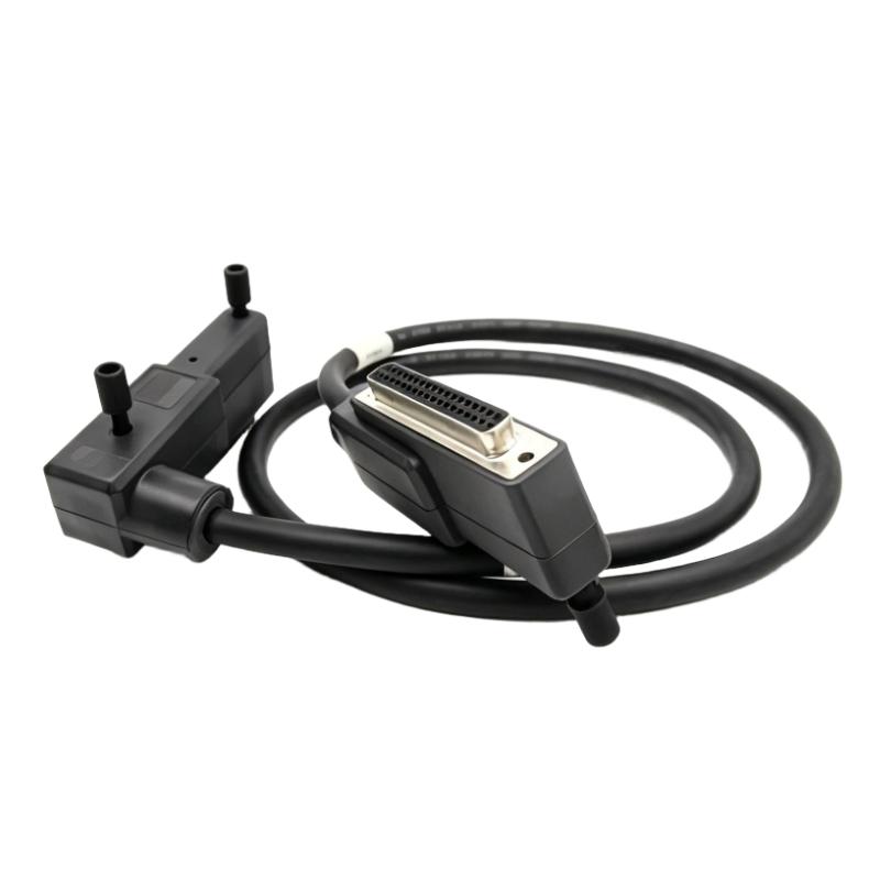
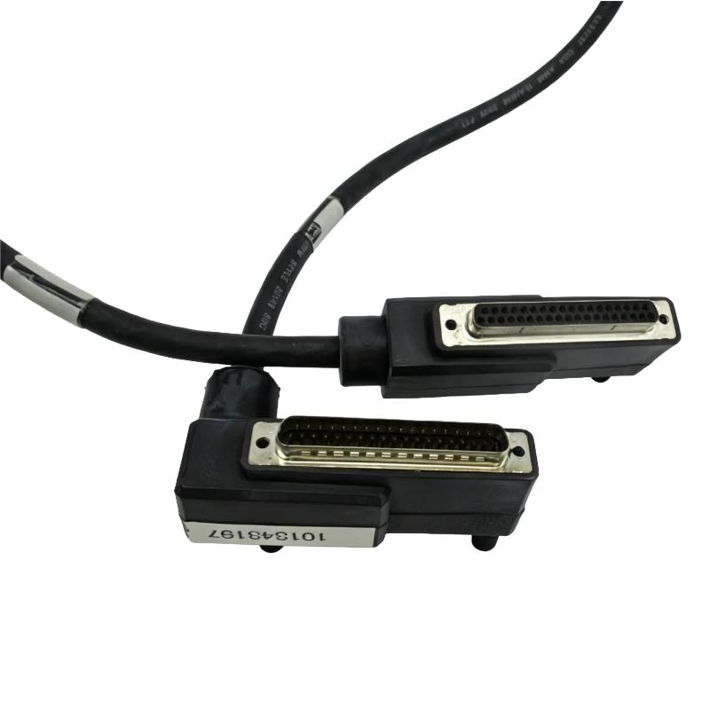
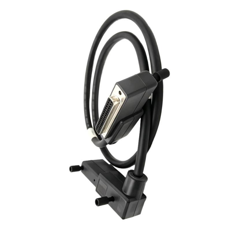
- Foxboro
- RH916FH
- Termination Cable
- USA
- 1 meter
- 3 kg
- Xiamen, China
- New & In Stock
- T/T, PayPal, Western Union
- 1 Year
- 1-3 Working Days
- DHL, UPS, TNT, FedEx and EMS.
- 24-Hour Service
- COO
- 6
Our advantage

Global Logistics
We have a 10-year logistics and express cooperation agreement, so our products can be shipped to any place in the world.

Brand new and original
Our products are imported in bulk from the place of origin. Because of the cooperative relationship, our products are all original and 100% new.

24-hour service
We provide 7*24 hours service to our customers. We will be there whenever you need us.

Price advantage
All our products are priced very favorably because we have our own warehouse and supply.
| Company Information | |||
| [email protected] | |||
| Mobile | +8615980777398 | ||
| +8615980777398 | |||
| 15980777398 |
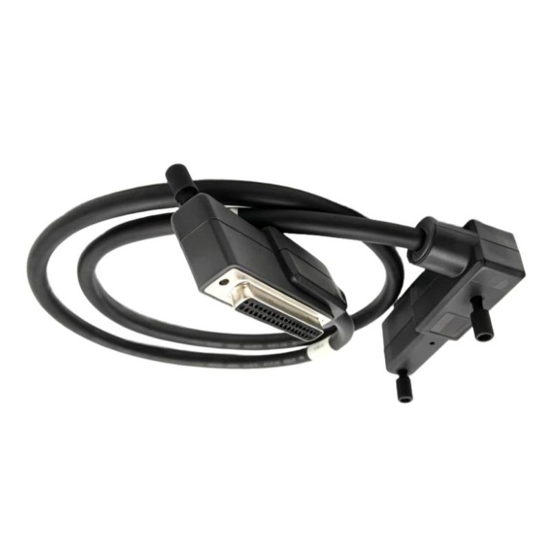
Product Overview
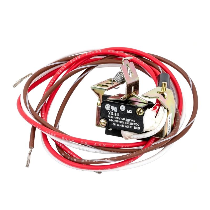
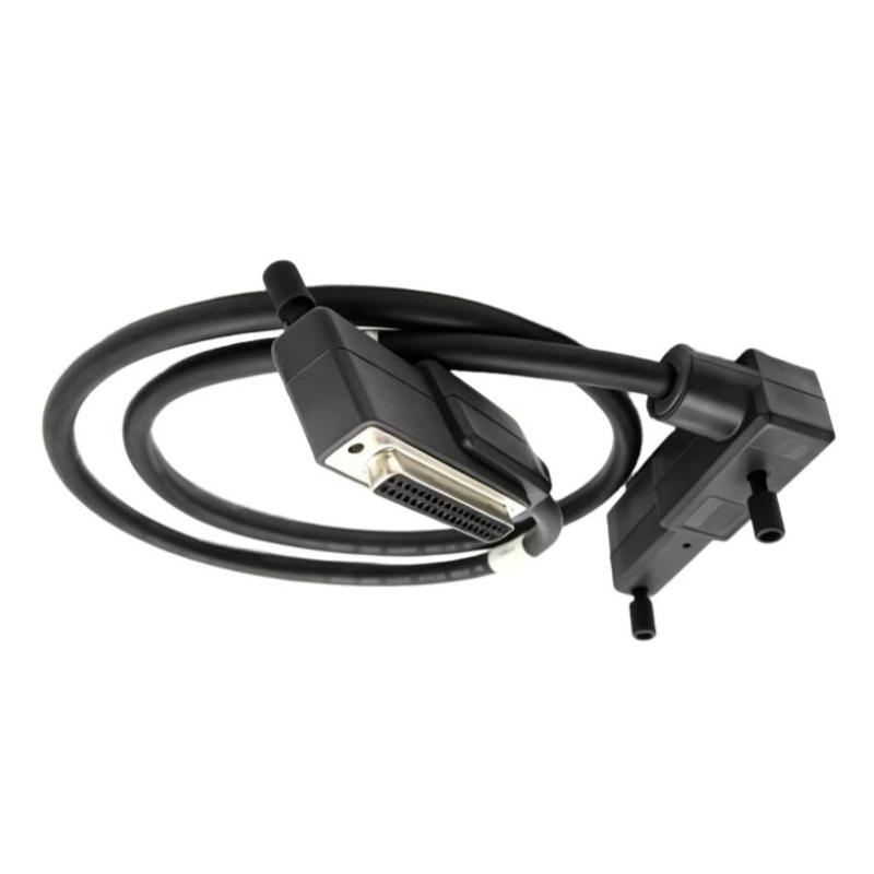
The Foxboro AD202MW I/A Series 200 Type 4 Termination Cable is an industrial control system cable associated with Foxboro I/A Series 200 installations. It forms part of the electrical interconnection infrastructure used to connect designated interfaces within a process control system.
In distributed control system cabinets, termination cables help establish the required electrical paths between system components. These connections are important during initial installation, cabinet expansion, routine maintenance, and replacement of damaged wiring assemblies. The AD202MW model reference and Type 4 designation are key identification details when matching a replacement cable to an existing installation.
During maintenance of a Foxboro control cabinet, technicians may need to replace a cable while preserving the existing wiring arrangement. Checking the complete part number, connection points, and associated termination hardware before removal helps prevent wiring mismatches and reduces unnecessary disruption to neighboring equipment.
The AD202MW is associated with the Foxboro I/A Series 200 control system environment. Its precise connection function should be established from the applicable system drawings and equipment documentation, particularly where several termination cable variants are installed in the same cabinet.
Technical Specifications
| Parameter | Specification |
|---|---|
| Manufacturer | Foxboro |
| Model | AD202MW |
| Product Family | I/A Series 200 |
| Product Type | Type 4 Termination Cable |
| Cable Category | Industrial Control System Cable |
| System Platform | Foxboro I/A Series 200 |
| Primary Function | Electrical interconnection |
| Application | Process control system wiring |
| Installation Environment | Industrial control cabinet or designated system wiring location |
| Cable Length | 1.5 meters |
| Shipping Weight | 3 kg |
Product Features
- Foxboro I/A Series 200 system cable designation
- Model AD202MW
- Type 4 termination cable identification
- Used as part of an industrial control system’s electrical interconnection infrastructure
- Supports designated connections within the installed termination arrangement
- Suitable for consideration during maintenance of existing Foxboro control installations
- Complete model reference helps distinguish the required cable from other cable assemblies
- Cable routing can be planned according to the physical layout of the control cabinet
- Supports replacement planning when an existing cable requires inspection or servicing
- Can be incorporated into documented control cabinet maintenance procedures
- Requires verification of the associated termination hardware before installation
- Supports organized wiring when routed and secured according to site requirements
- Applicable to maintenance tasks involving established I/A Series 200 wiring arrangements
- Selection should be based on the specified part number and connection requirements rather than a similar product description
Working Principle
The AD202MW serves as a passive electrical interconnection within the relevant control system wiring arrangement.
Designated System Interface → AD202MW Termination Cable → Associated Termination or Control Interface
The cable establishes the physical electrical path between the interfaces specified for the installation. The connected hardware determines how signals are acquired, processed, or used by the control application. The cable itself does not execute control logic or independently perform signal conversion.
In a typical maintenance situation, technicians identify the cable’s endpoints from the wiring drawings before disconnecting the existing assembly. The replacement cable is then routed and connected according to the documented arrangement. Correct connector seating and cable routing help preserve the intended electrical connection and prevent avoidable wiring faults.
The cable’s function depends on the equipment to which it is connected. A fault affecting the connection path may originate from the cable, its connectors, the termination points, or the associated hardware. Checking the complete path helps distinguish a wiring problem from an issue elsewhere in the control system.
After installation, technicians should carry out the inspection and functional checks required by the applicable maintenance procedure before returning the affected equipment to service.
Role in a Foxboro I/A Series 200 Control Architecture
The AD202MW is associated with the interconnection layer of a Foxboro I/A Series 200 installation. Its specific position depends on the termination hardware and system configuration documented for the equipment.
System Wiring → Termination Arrangement → AD202MW Cable Connection → Associated Control Hardware → Control Application
| System Element | Function |
|---|---|
| AD202MW | Identifies the Type 4 termination cable used in the specified installation |
| Termination Assembly | Provides designated electrical connection points |
| Field Wiring | Carries electrical signals between field devices and system connection points |
| I/O Hardware | Handles signal acquisition or output according to the module’s function |
| I/A Series 200 Control Hardware | Supports configured process monitoring and control functions |
| System Power Supply | Supplies power to the relevant equipment where required |
| Control Cabinet Wiring | Provides the physical routing for electrical interconnections |
| Controller Hardware | Executes configured control logic using available process information |
| Operator Workstation or HMI | Displays process information and supports operator interaction |
The cable should be identified within the actual system architecture using the equipment drawings. Its model designation alone does not establish a specific controller, I/O channel, or termination board assignment.
Industrial Applications
| Application | Typical Use |
|---|---|
| Process Automation | Maintaining cable connections within distributed control system installations |
| Chemical Processing | Servicing control cabinet wiring in process plants |
| Oil and Gas Facilities | Maintaining established interconnections in compatible control installations |
| Power Generation | Supporting maintenance of process control wiring infrastructure |
| Water and Wastewater Treatment | Maintaining designated connections in process monitoring systems |
| Petrochemical Plants | Replacing identified cable assemblies during control cabinet maintenance |
| Manufacturing Facilities | Maintaining wiring connections associated with industrial control equipment |
| Industrial Utilities | Supporting maintenance of process monitoring and control infrastructure |
| Control Cabinet Refurbishment | Replacing an identified cable while preserving the documented wiring arrangement |
| Plant Maintenance Operations | Restoring electrical connections following cable damage or troubleshooting |
Installation and Maintenance
- Confirm the complete AD202MW model reference before ordering or installing the cable.
- Review the applicable Foxboro I/A Series 200 system documentation to identify the intended connection points and termination arrangement.
- Follow site electrical isolation and maintenance procedures before disconnecting existing control system wiring.
- Record the existing cable route and connection points before removal, particularly where multiple cable assemblies are installed in the same cabinet.
- Inspect the replacement cable and accessible connectors for visible damage, deformation, or signs of improper handling.
- Verify that the cable designation and connection arrangement match the requirements of the installed termination hardware.
- Disconnect the existing cable carefully according to the applicable procedure, avoiding unnecessary force on the cable and connectors.
- Route the replacement cable along the intended path, avoiding sharp edges, excessive bending, and interference with adjacent equipment.
- Connect the AD202MW to the designated interfaces according to the system wiring drawings.
- Inspect the completed installation for loose connections, cable strain, unsecured routing, and interference with neighboring wiring.
- Perform the applicable connection, continuity, or functional checks specified by the equipment documentation before returning the system to service.
- Record the replacement model, inspection findings, and any changes to the cable route or connection arrangement in the maintenance records.
Related Components
| Component | Function |
|---|---|
| Foxboro I/A Series 200 Control Hardware | Supports the configured control functions of the installation |
| Termination Assembly | Provides designated electrical connection points |
| I/O Module | Handles signal acquisition or output according to its specific function |
| Field Instrument Wiring | Connects field devices to the relevant termination arrangement |
| Control Cabinet Wiring Accessories | Support cable routing and organization |
| System Power Supply | Supplies power to associated equipment where required |
| Controller Hardware | Executes the configured control application |
| Operator Workstation or HMI | Presents process status and operator controls |
| System Wiring Drawings | Identify cable endpoints and connection assignments |
Recommended Related Models
| Model / Product Family | Product Type | Typical Application |
|---|---|---|
| Foxboro AD202MW | Type 4 Termination Cable | Specified model for this product entry |
| Foxboro P0916FH | I/A Series 200 Type 4 P/PVC Termination Cable | Related Type 4 cable designation; verify the required connections before substitution |
| Foxboro RH916FH | I/A Series 200 Type 4 P/PVC Termination Cable | Related Type 4 cable designation; confirm the exact system application |
| Foxboro P0916DW | I/A Series 200 Type 2 P/PVC Termination Cable | Type 2 cable variant for installations specifying this model |
| Foxboro RH916DW | I/A Series 200 Type 2 P/PVC Termination Cable | Alternative model designation for installations requiring the specified Type 2 cable |
Key Advantages
- Identifiable model reference for maintenance and replacement planning.
- Type 4 designation supports cable identification.
- Supports electrical interconnection within the specified control system wiring arrangement.
- Helps technicians trace and restore established cabinet connections.
- Suitable for planned maintenance when the specified model matches the installed configuration.
- Supports organized cable routing and documented maintenance practices.
Technical FAQs
What Is the Foxboro AD202MW I/A Series 200 Type 4 Termination Cable Used For?
The Foxboro AD202MW is identified as a Type 4 termination cable associated with the I/A Series 200 control system environment. It forms part of the electrical interconnection infrastructure between designated system interfaces. Its exact connection points should be confirmed from the applicable equipment documentation.
How Can Engineers Verify AD202MW Compatibility With a Foxboro I/A Series 200 System?
Engineers should check the complete AD202MW part number against the installed termination hardware, system wiring drawings, and equipment records. The I/A Series 200 designation alone does not establish compatibility with every cabinet configuration or connection arrangement.
Can the Foxboro AD202MW Be Replaced With Another Type 4 Termination Cable?
A matching Type 4 description does not establish that two cable models are interchangeable. Before selecting a substitute, verify the manufacturer’s part-number cross-reference, connector arrangement, and intended system application. If equivalence cannot be confirmed, use the model specified in the equipment documentation.
How Should a Fault in an AD202MW Termination Cable Connection Be Diagnosed?
Inspect the cable and connectors for visible damage, loose connections, or incorrect seating. Check the documented connection points and follow the applicable procedure for testing the electrical path. If the connection remains faulty, investigate the associated termination hardware and control system interfaces to determine whether the problem originates beyond the cable itself.