

ProductPRODUCT
Featured products

Contact Us
- GE
- IS230TAISH2C
- DIN Rail Assembly
- USA
- 100 x 132 x 57 mm
- 1.2 kg
- Xiamen, China
- New & In Stock
- T/T, PayPal, Western Union
- 1 Year
- 1-3 Working Days
- DHL, UPS, TNT, FedEx and EMS.
- 24-Hour Service
- COO
- 7
Our advantage

Global Logistics
We have a 10-year logistics and express cooperation agreement, so our products can be shipped to any place in the world.

Brand new and original
Our products are imported in bulk from the place of origin. Because of the cooperative relationship, our products are all original and 100% new.

24-hour service
We provide 7*24 hours service to our customers. We will be there whenever you need us.

Price advantage
All our products are priced very favorably because we have our own warehouse and supply.
| Company Information | |||
| [email protected] | |||
| Mobile | +8615980777398 | ||
| +8615980777398 | |||
| 15980777398 |
Product Overview
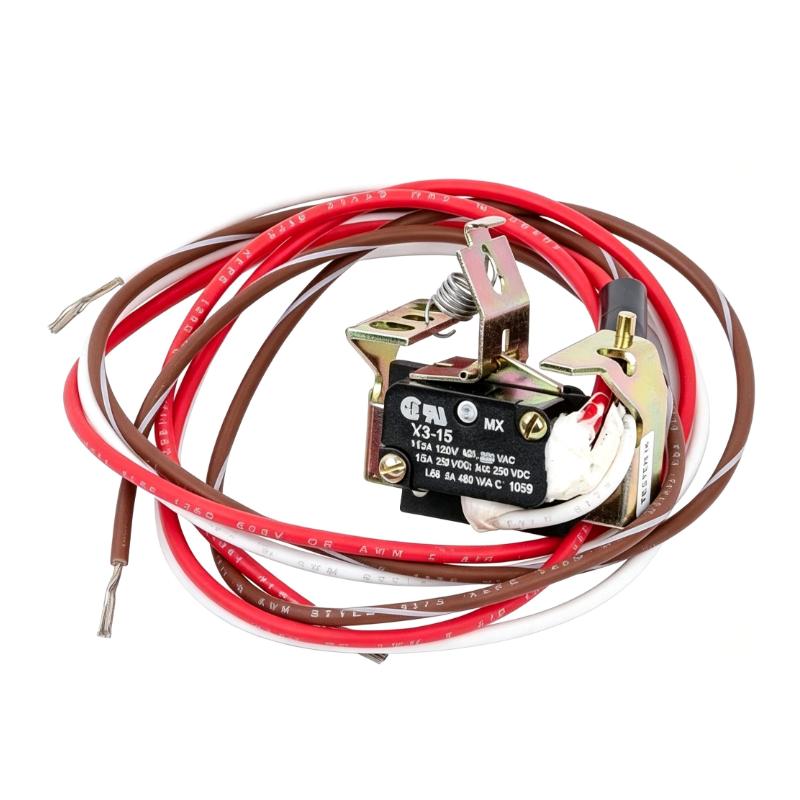
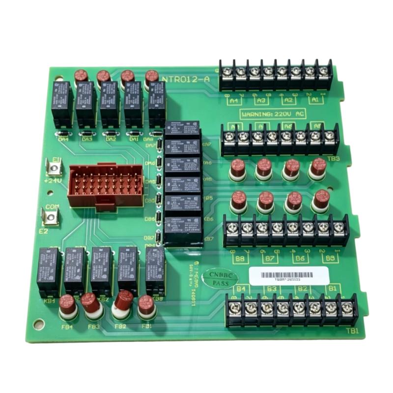
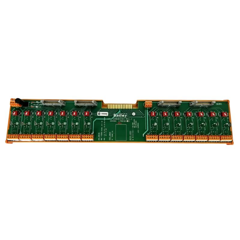
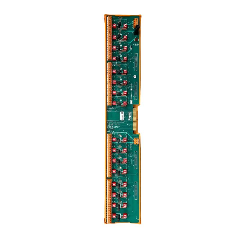
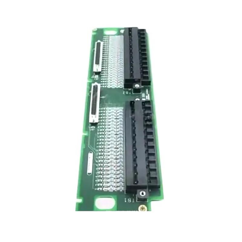
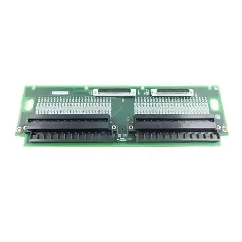
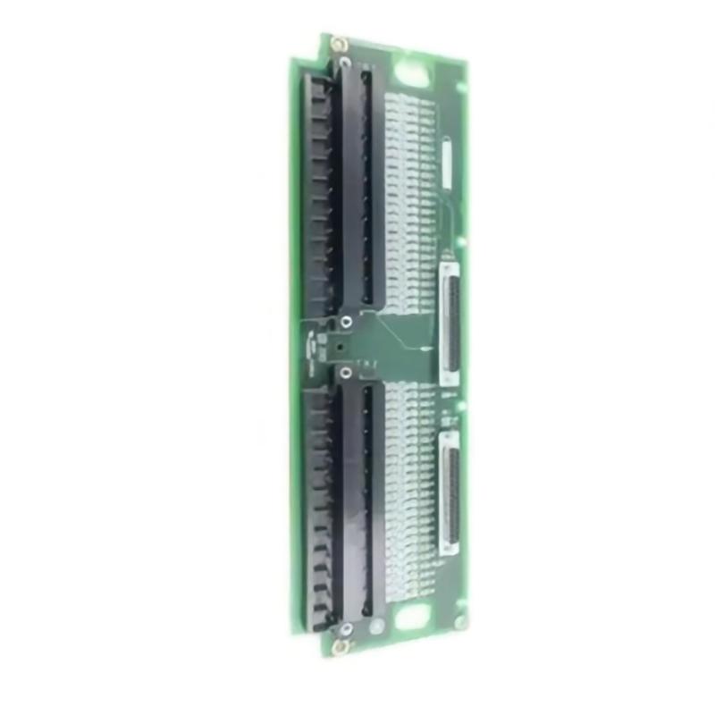
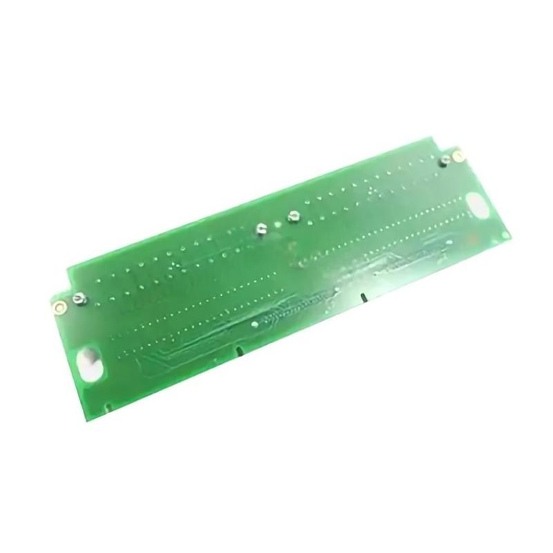
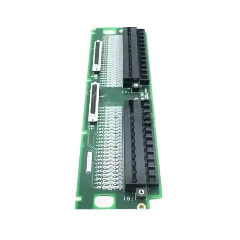
The GE IS230TAISH2C DIN Rail Assembly is an industrial automation component intended for integration into compatible GE control equipment. DIN rail assemblies help organize and secure control hardware within industrial cabinets, providing a structured arrangement for electrical connections and associated electronic components.
In industrial automation environments, modular assemblies support the integration of control electronics, signal interfaces, field wiring, and monitoring equipment. Correctly identifying each assembly is important for maintaining system reliability, simplifying maintenance, and ensuring that replacement components match the original installation.
The GE IS230TAISH2C has supplied dimensions of 100 × 132 × 57 mm and a weight of approximately 1.2 kg. Its compact footprint can be useful when planning cabinet layouts, organizing spare parts, or preparing replacement equipment for maintenance work.
The exact electrical function, interface characteristics, and compatible host equipment for the IS230TAISH2C should be confirmed using the complete hardware identification and the applicable system documentation. The product designation alone should not be used to infer its signal type, channel count, or electrical ratings.
Technical Specifications
| Parameter | Specification |
|---|---|
| Manufacturer | General Electric (GE) |
| Model | IS230TAISH2C |
| Product Type | DIN Rail Assembly |
| Product Family | GE IS230 Series |
| Primary Role | Industrial control assembly |
| Mounting Arrangement | DIN rail assembly, subject to configuration verification |
| Dimensions | 100 × 132 × 57 mm |
| Weight | 1.2 kg |
| Installation Environment | Compatible industrial control cabinet |
| Application | Industrial automation and control equipment |
| Electrical Characteristics | Confirm from the applicable hardware documentation |
| Replacement Requirement | Verify part number, revision, interfaces, and host-system compatibility |
Function and Working Principle
The function of the IS230TAISH2C depends on the specific control equipment in which it is installed. A DIN rail assembly can provide a mechanical mounting structure, an electrical interface, or a combination of supporting functions within a larger automation system.
In a typical industrial control installation, modular hardware works together through several stages:
- Mechanical installation: The assembly is secured in its designated cabinet position.
- Electrical connection: Relevant power, signal, or interface connections are made according to the approved wiring arrangement.
- Interaction with associated hardware: The assembly operates alongside compatible control electronics and other system components.
- System operation: The wider control architecture uses its configured hardware to monitor equipment, process signals, or coordinate control functions.
- Maintenance and diagnostics: Technicians inspect connections, review system status, and investigate faults when required.
These stages describe a general modular control arrangement. The specific functions performed by the IS230TAISH2C must be confirmed for the installed system rather than inferred from the DIN rail designation alone.
Role in Industrial Automation
Industrial automation systems rely on correctly installed and compatible hardware to maintain dependable operation. Modular assemblies help organize equipment and establish the required physical and electrical relationships between components.
Depending on its verified role, the IS230TAISH2C may form part of a cabinet-based control arrangement involving:
- Industrial control electronics
- Signal interface hardware
- Field wiring and terminal connections
- Supporting power and connection assemblies
- Monitoring and diagnostic equipment
- Cabinet mounting and organization hardware
A correctly identified assembly can simplify maintenance, support orderly component replacement, and reduce the risk of installing hardware that does not match the original configuration.
Industrial Applications
Power Generation
Industrial control equipment in power-generation facilities must be maintained according to precise hardware configurations. Modular assemblies are used throughout control cabinets to support the organization and integration of system components.
Turbine and Auxiliary Equipment
Turbine installations may contain multiple electronic assemblies, wiring interfaces, and supporting hardware. Replacement parts must match the intended system position and configuration.
Process Automation
Manufacturing and process facilities use modular control cabinets to coordinate instrumentation, monitoring, and automated equipment. Correct hardware identification helps maintain the integrity of these installations.
Industrial Machinery
Machinery control cabinets frequently contain a combination of mounting assemblies, signal interfaces, processors, and power-related components. Appropriate assembly selection supports maintainability and organized installation.
Legacy Control-System Maintenance
For existing industrial installations, sourcing the correct replacement assembly can help preserve the established system architecture and reduce unnecessary modifications.
These are representative industrial environments in which modular control assemblies may be used. Suitability for a particular application should be confirmed against the IS230TAISH2C’s actual specifications and host-system requirements.
Installation and System Integration
Proper installation helps prevent mechanical damage, wiring errors, and avoidable downtime. The IS230TAISH2C should be handled by qualified personnel using the approved procedures for the equipment in which it is installed.
1. Verify the Assembly Identification
Confirm the complete IS230TAISH2C model number, revision markings, labels, connectors, and original mounting position. Do not select a replacement solely because its dimensions or appearance are similar.
2. Isolate the Equipment
Follow the site’s approved shutdown, electrical isolation, and lockout procedures before opening the control cabinet or handling the assembly. Ensure the equipment is in a safe condition before beginning work.
3. Inspect the Mounting Position
Check the designated installation area for physical damage, loose hardware, contamination, or signs of overheating. Verify that the assembly matches the required mounting arrangement.
4. Check Associated Connections
Inspect relevant connectors and wiring for loose contacts, damaged insulation, corrosion, or mechanical strain. Record existing connections before removing the original assembly, and use the approved wiring diagrams when reconnecting conductors.
5. Install the Assembly
Secure the component in its designated position using the specified mounting method. Ensure that the assembly is stable and that associated wiring is not excessively bent or strained.
6. Verify Configuration
Confirm that the installed part number and revision are appropriate for the host equipment. Check the associated hardware configuration and any required parameter settings using the applicable system documentation.
7. Perform Commissioning Checks
After installation, inspect all connections and follow the approved startup procedure. Review available diagnostics and verify that the system operates as expected before returning the equipment to normal service.
Troubleshooting Guide
Troubleshooting should consider the assembly, its connections, and the surrounding control equipment. A system fault does not necessarily mean that the assembly itself has failed.
Assembly Not Recognized
Possible causes include incorrect hardware identification, an incompatible revision, a poor connection, improper installation, or a host-system configuration issue.
Recommended checks:
- Verify the complete model number and revision.
- Inspect connectors and mounting.
- Confirm the assembly occupies the correct position.
- Review available system diagnostics.
- Verify compatibility with the associated hardware.
Intermittent System Faults
Intermittent problems can be associated with loose connections, damaged wiring, vibration, contamination, or faults in related components.
Inspect the installation and record when the fault occurs. Review diagnostic information before replacing additional hardware.
Unexpected System Behavior
Unexpected behavior may result from incorrect configuration, a connection problem, incompatible hardware, or a fault elsewhere in the control system.
Verify the system configuration and investigate the complete signal or connection path using the approved troubleshooting procedure. Avoid assuming a specific electrical fault without evidence.
Problems After Replacement
If a fault persists after replacing the assembly, confirm that the replacement matches the required part number and revision. Inspect the surrounding wiring, mounting arrangement, connected equipment, and system configuration.
A replacement component cannot resolve a fault caused by another part of the installation.
Maintenance Recommendations
Routine maintenance helps identify developing problems and supports dependable operation.
- Inspect physical condition: Look for damaged housing, loose mounting hardware, or visible signs of overheating.
- Check connectors and wiring: Inspect for corrosion, contamination, loose connections, and damaged insulation.
- Maintain cabinet conditions: Keep the installation within the environmental limits specified for the host equipment.
- Review diagnostic records: Investigate repeated alarms or unexplained changes in system behavior.
- Use appropriate handling precautions: Follow electrostatic-discharge procedures when handling sensitive electronic hardware.
- Maintain identification records: Record the model number, revision, installation date, and maintenance history.
- Follow approved procedures: Perform inspection and testing according to the requirements of the installed control system.
Maintenance intervals should reflect the equipment’s operating environment, criticality, and manufacturer-approved maintenance requirements.
Compatible System Components
The IS230TAISH2C should be assessed as part of the complete control assembly. Depending on the verified installation, a surrounding system may include the following component categories:
| Component Category | Typical Function |
|---|---|
| Control Processor | Executes configured control logic |
| Interface Assembly | Provides a designated connection between system components |
| Signal Hardware | Handles specified input or output signals |
| Power Components | Supply power to designated equipment |
| Terminal Assemblies | Organize field wiring connections |
| Communication Hardware | Supports data exchange where required |
| Cabinet Mounting Hardware | Secures and organizes installed assemblies |
| Diagnostic Equipment | Supports inspection and fault investigation |
This table describes general industrial control component categories. It does not confirm direct compatibility between the IS230TAISH2C and any specific module or controller. The actual configuration must be verified before installation.
Replacement and Procurement Considerations
When sourcing a GE IS230TAISH2C DIN Rail Assembly, accurate identification is essential. Industrial control components can share similar physical dimensions while having different electrical functions and system requirements.
Before ordering, verify:
- Complete part number: IS230TAISH2C
- Revision and label markings
- Product function within the host system
- Mounting and connector arrangements
- Associated hardware requirements
- Compatibility with the existing control configuration
- Physical condition and packaging
- Required commissioning or configuration procedures
The supplied dimensions are 100 × 132 × 57 mm, and the supplied weight is 1.2 kg. These specifications are useful for inventory, shipping, and cabinet-planning purposes, but physical measurements alone cannot establish electrical compatibility.
Technical FAQs
What is the GE IS230TAISH2C?
The GE IS230TAISH2C is identified as a DIN Rail Assembly for industrial control equipment. Its exact electrical role should be confirmed using the applicable hardware documentation.
What are its dimensions?
The supplied dimensions are 100 × 132 × 57 mm.
How much does the IS230TAISH2C weigh?
The supplied weight is approximately 1.2 kg.
Can it be installed in any DIN rail cabinet?
No. Installation depends on the specified mounting arrangement, associated connections, environmental requirements, and compatibility with the host system.
Can another GE IS230 assembly replace it?
Not automatically. The replacement must match the intended function, required interfaces, hardware revision requirements, and host-system configuration.
What should be checked if the system develops a fault after installation?
Verify the assembly identification, mounting, connectors, wiring, configuration, and available diagnostics. If the problem persists, investigate the associated control equipment before concluding that the assembly is defective.
Conclusion
The GE IS230TAISH2C DIN Rail Assembly is an industrial control component with supplied dimensions of 100 × 132 × 57 mm and a weight of approximately 1.2 kg. These specifications support component identification, cabinet planning, inventory management, and replacement logistics.
Reliable integration depends on confirming the assembly’s exact function, verifying compatibility with the host equipment, and following approved installation and commissioning procedures. For maintenance and procurement, checking the complete part number and revision is essential to reduce the risk of an incompatible replacement and support dependable industrial control-system operation.